Bird J. Electrical Circuit Theory and Technology
Подождите немного. Документ загружается.

868 Electrical Circuit Theory and Technology
250∠0° V
50 Hz
5 Ω
50 mH 120 mH
I
g
15 Ω 25 Ω
I
L
50 Ω
M = 30 mH
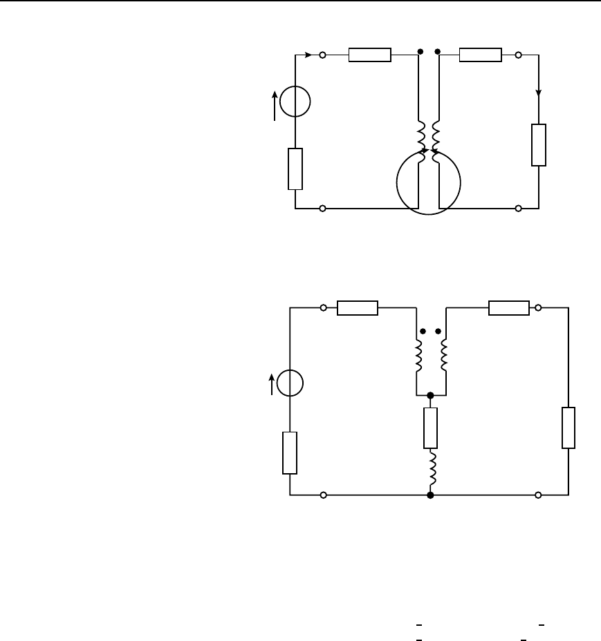
Figure 43.27
50 Ω15 Ω
20 mH
120 mH
25 Ω15 Ω
5 Ω
50 mH
M = 30 mH
250∠0° V
50 Hz
Figure 43.28
20 The mutual inductor of problem 19 is connected to the circuit as
shown in Figure 43.28. Determine (a) the source current, and (b) the
load current. (c) If one of the windings is reversed, determine the
new value of source and load currents.
[(a) 6.658
6
28.07
°
A (b) 1.444
6
7.79
°
A
(c) 8.239
6
23.09
°
A, 1.261
6
60.96
°
A]

44 Transmission lines
At the end of this chapter you should be able to:
ž appreciate the purpose of a transmission line
ž define the transmission line primary constants R, L, C and G
ž calculate phase delay, wavelength and velocity of propagation
on a transmission line
ž appreciate current and voltage relationships on a transmission
line
ž define the transmission line secondary line constants Z
0
, , ˛
and ˇ
ž calculate characteristic impedance and propagation coefficient
in terms of the primary line constants
ž understand and calculate distortion on transmission lines
ž understand wave reflection and calculate reflection coefficient
ž understand standing waves and calculate standing wave ratio
44.1 Introduction
A transmission line is a system of conductors connecting one point
to another and along which electromagnetic energy can be sent. Thus
telephone lines and power distribution lines are typical examples of
transmission lines; in electronics, however, the term usually implies a
line used for the transmission of radio-frequency (r.f.) energy such as that
from a radio transmitter to the antenna.
An important feature of a transmission line is that it should guide energy
from a source at the sending end to a load at the receiving end without
loss by radiation. One form of construction often used consists of two
similar conductors mounted close together at a constant separation. The
two conductors form the two sides of a balanced circuit and any radiation
from one of them is neutralized by that from the other. Such twin-wire
lines are used for carrying high r.f. power, for example, at transmitters.
The coaxial form of construction is commonly employed for low power
use, one conductor being in the form of a cylinder which surrounds the
other at its centre, and thus acts as a screen. Such cables are often used
to couple f.m. and television receivers to their antennas.
At frequencies greater than 1000 MHz, transmission lines are usually
in the form of a waveguide which may be regarded as coaxial lines
without the centre conductor, the energy being launched into the guide or
abstracted from it by probes or loops projecting into the guide.
44.2 Transmission line
primary constants
Let an a.c. generator be connected to the input terminals of a pair of
parallel conductors of infinite length. A sinusoidal wave will move along

870 Electrical Circuit Theory and Technology
the line and a finite current will flow into the line. The variation of voltage
with distance along the line will resemble the variation of applied voltage
with time. The moving wave, sinusoidal in this case, is called a voltage
travelling wave. As the wave moves along the line the capacitance of the
line is charged up and the moving charges cause magnetic energy to be
stored. Thus the propagation of such an electromagnetic wave constitutes
a flow of energy.
After sufficient time the magnitude of the wave may be measured at any
point along the line. The line does not therefore appear to the generator
as an open circuit but presents a definite load Z
0
. If the sending-end
voltage is V
S
and the sending end current is I
S
then Z
0
D V
S
/I
S
. Thus
all of the energy is absorbed by the line and the line behaves in a similar
manner to the generator as would a single ‘lumped’ impedance of value
Z
0
connected directly across the generator terminals.
There are four parameters associated with transmission lines, these
being resistance, inductance, capacitance and conductance.
(i) Resistance R is given by R D l/A, where is the resistivity of the
conductor material, A is the cross-sectional area of each conductor
and l is the length of the conductor (for a two-wire system, l repre-
sents twice the length of the line). Resistance is stated in ohms
per metre length of a line and represents the imperfection of the
conductor. A resistance stated in ohms per loop metre is a little
more specific since it takes into consideration the fact that there are
two conductors in a particular length of line.
(ii) Inductance L is due to the magnetic field surrounding the conduc-
tors of a transmission line when a current flows through them. The
inductance of an isolated twin line is considered in Section 40.7.
From equation (40.23), page 748, the inductance L is given by
L D
0
r
1
4
C ln
D
a
henry/metre
where D is the distance between centres of the conductor and a is
the radius of each conductor. In most practical lines
r
D 1. An
inductance stated in henrys per loop metre takes into consideration
the fact that there are two conductors in a particular length of line.
(iii) Capacitance C exists as a result of the electric field between conduc-
tors of a transmission line. The capacitance of an isolated twin line
is considered in Section 40.3. From equation (40.14), page 736, the
capacitance between the two conductors is given by
C D
ε
0
ε
r
lnD/a
farads/metre
In most practical lines ε
r
D 1
(iv) Conductance G is due to the insulation of the line allowing some
current to leak from one conductor to the other. Conductance
is measured in siemens per metre length of line and represents
Transmission lines 871
the imperfection of the insulation. Another name for conductance
is leakance.
Each of the four transmission line constants, R, L, C and G, known as
the primary constants, are uniformly distributed along the line.
From Chapter 41, when a symmetrical T-network is terminated in its
characteristic impedance Z
0
, the input impedance of the network is also
equal to Z
0
. Similarly, if a number of identical T-sections are connected
in cascade, the input impedance of the network will also be equal to Z
0
.
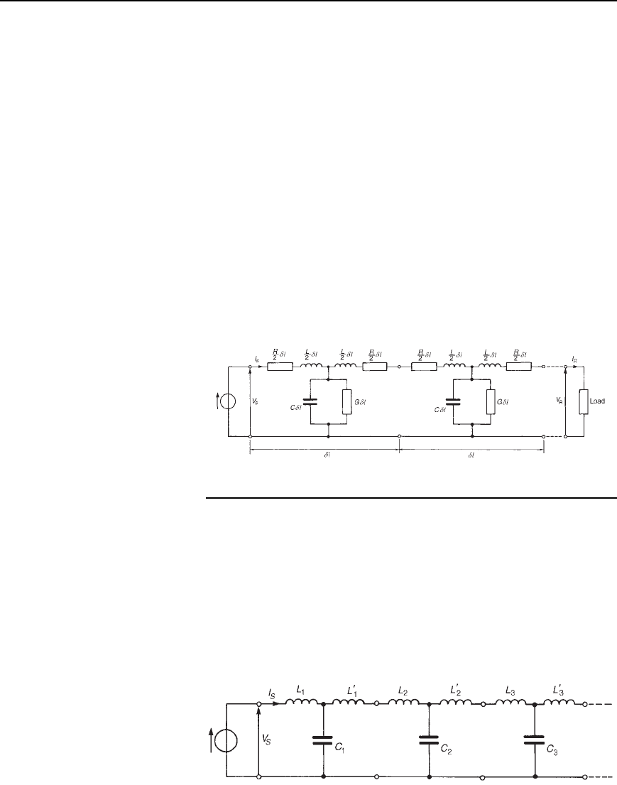
A transmission line can be considered to consist of a network of a
very large number of cascaded T-sections each a very short length (υl)of
transmission line, as shown in Figure 44.1. This is an approximation of
the uniformly distributed line; the larger the number of lumped parameter
sections, the nearer it approaches the true distributed nature of the line.
When the generator V
S
is connected, a current I
S
flows which divides
between that flowing through the leakage conductance G, which is lost,
and that which progressively charges each capacitor C and which sets up
the voltage travelling wave moving along the transmission line. The loss
or attenuation in the line is caused by both the conductance G and the
series resistance R.
Figure 44.1
44.3 Phase delay,
wavelength and velocity of
propagation
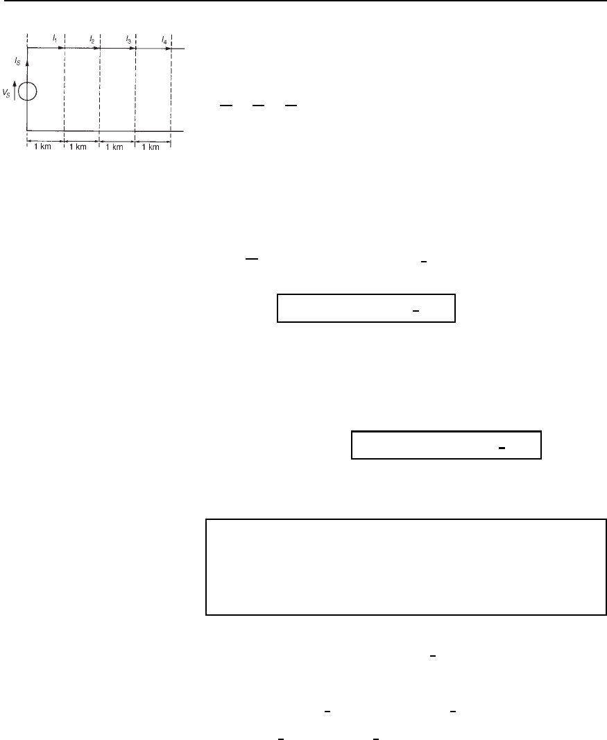
Each section of that shown in Figure 44.1 is simply a low-pass filter
possessing losses R and G. If losses are neglected, and R and G are
removed, the circuit simplifies and the infinite line reduces to a repetitive
T-section low-pass filter network as shown in Figure 44.2. Let a generator
be connected to the line as shown and let the voltage be rising to a
maximum positive value just at the instant when the line is connected
to it. A current I
S
flows through inductance L
1
into capacitor C
1
. The
capacitor charges and a voltage develops across it. The voltage sends a
current through inductance L
0
1
and L
2
into capacitor C
2
. The capacitor
Figure 44.2

872 Electrical Circuit Theory and Technology
charges and the voltage developed across it sends a current through L
0
2
and L
3
into C
3
, and so on. Thus all capacitors will in turn charge up
to the maximum input voltage. When the generator voltage falls, each
capacitor is charged in turn in opposite polarity, and as before the input
charge is progressively passed along to the next capacitor. In this manner
voltage and current waves travel along the line together and depend on
each other.
The process outlined above takes time; for example, by the time capac-
itor C
3
has reached its maximum voltage, the generator input may be at
zero or moving towards its minimum value. There will therefore be a
time, and thus a phase difference between the generator input voltage and
the voltage at any point on the line.
Phase delay
Since the line shown in Figure 44.2 is a ladder network of low-pass T-
section filters, it is shown in equation (42.27), page 820, that the phase
delay, ˇ, is given by:
b = !
p
.LC/ radians=metre
44.1
where L and C are the inductance and capacitance per metre of the line.
Wavelength
The wavelength on a line is the distance between a given point and
the next point along the line at which the voltage is the same phase, the
initial point leading the latter point by 2 radian. Since in one wavelength
a phase change of 2 radians occurs, the phase change per metre is 2/.
Hence, phase change per metre, ˇ D 2/
or
wavelength, l D
2p
b
metres
44.2
Velocity of propagation
The velocity of propagation, u, is given by u D f, where f is the
frequency and the wavelength. Hence
u D f l D f 2p/b D
2pf
b
D
!
b
44.3
The velocity of propagation of free space is the same as that of light,
i.e., approximately 300 ð 10
6
m/s. The velocity of electrical energy along
a line is always less than the velocity in free space. The wavelength
of radiation in free space is given by D c/f where c is the velocity of
light. Since the velocity along a line is always less than c, the wavelength

Transmission lines 873
corresponding to any particular frequency is always shorter on the line
than it would be in free space.
Problem 1. A parallel-wire air-spaced transmission line operating
at 1910 Hz has a phase shift of 0.05 rad/km. Determine (a) the
wavelength on the line, and (b) the speed of transmission of a
signal.
(a) From equation (44.2), wavelength D 2/ˇ D 2/0.05
D 125.7km
(b) From equation (44.3), speed of transmission,
u D f D 1910125.7 D 240
× 10
3
km=s or 240 × 10
6
m=s
Problem 2. A transmission line has an inductance of 4 mH/loop
km and a capacitance of 0.004
µF/km. Determine, for a frequency
of operation of 1 kHz, (a) the phase delay, (b) the wavelength on
the line, and (c) the velocity of propagation (in metres per second)
of the signal.
(a) From equation (44.1), phase delay,
ˇ D ω
p
LC D 21000
[4 ð 10
3
0.004 ð 10
6
]
D 0.025 rad=km
(b) From equation (44.2), wavelength D 2/ˇ D 2/0.025
D 251 km
(c) From equation (44.3), velocity of propagation,
u D f D 1000251 km/s D 251
× 10
6
m=s
Further problems on phase delay, wavelength and velocity of propagation
may be found in Section 44.9, problems 1 to 3, page 897.
44.4 Current and voltage
relationships
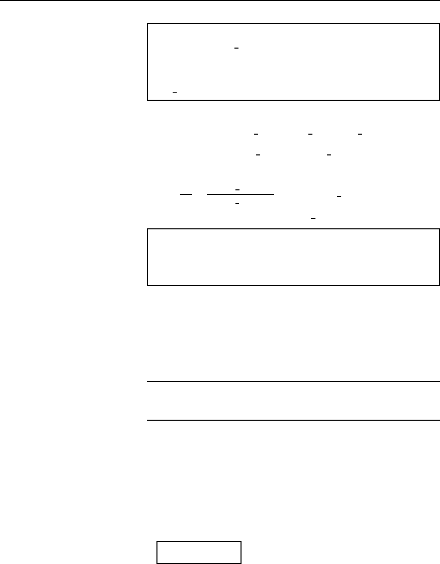
Figure 44.3 shows a voltage source V
S
applied to the input terminals of
an infinite line, or a line terminated in its characteristic impedance, such
that a current I
S
flows into the line. At a point, say, 1 km down the line
let the current be I
1
. The current I
1
will not have the same magnitude as
I
S
because of line attenuation; also I
1
will lag I
S
by some angle ˇ. The
ratio I
S
/I
1
is therefore a phasor quantity. Let the current a further 1 km
874 Electrical Circuit Theory and Technology
Figure 44.3
down the line be I
2
, and so on, as shown in Figure 44.3. Each unit length
of line can be treated as a section of a repetitive network, as explained in
Section 44.2. The attenuation is in the form of a logarithmic decay and
I
S
I
1
D
I
1
I
2
D
I
2
I
3
D e
where is the propagation constant, first introduced in Section 42.7,
page 815. has no unit.
The propagation constant is a complex quantity given by D ˛ C jˇ,
where ˛ is the attenuation constant, whose unit is the neper, and ˇ is
the phase shift coefficient, whose unit is the radian. For n such 1 km
sections, I
S
/I
R
D e
n
where I
R
is the current at the receiving end.
Hence
I
S
I
R
D e
n˛Cjˇ
D e
n˛Cjnˇ
D e
n˛
6
nˇ
from which,
I
R
D I
S
e
−ng
D I
S
e
−na
66
nb
44.4
In equation (44.4), the attenuation on the line is given by n˛ nepers and
the phase shift is nˇ radians.
At all points along an infinite line, the ratio of voltage to current is Z
0
,
the characteristic impedance. Thus from equation (44.4) it follows that:
receiving end voltage,
V
R
D V
S
e
−ng
D V
S
e
−na
66
nb
44.5
Z
0
, , ˛,andˇ are referred to as the secondary line constants or coef-
ficients.
Problem 3. When operating at a frequency of 2 kHz, a cable has
an attenuation of 0.25 Np/km and a phase shift of 0.20 rad/km. If a
5 V rms signal is applied at the sending end, determine the voltage
at a point 10 km down the line, assuming that the termination is
equal to the characteristic impedance of the line.
Let V
R
be the voltage at a point n km from the sending end, then from
equation (44.5), V
R
D V
S
e
n
D V
S
e
n˛
6
nˇ
Since ˛ D 0.25 Np/km, ˇ D 0.20 rad/km, V
S
D 5Vandn D 10 km, then
V
R
D 5e
100.25
6
100.20 D 5e
2.5
6
2.0V
D 0.41
66
−2.0Vor 0.41
66
−114.6
°
V
Thus the voltage 10 km down the line is 0.41 V rms lagging the sending
end voltage o
f5Vby2.0rador114.6
°
Transmission lines 875
Problem 4. A transmission line 5 km long has a characteristic
impedance of 800
6
25
°
#. At a particular frequency, the atten-
uation coefficient of the line is 0.5 Np/km and the phase shift
coefficient is 0.25 rad/km. Determine the magnitude and phase
of the current at the receiving end, if the sending end voltage is
2.0
6
0
°
V r.m.s.
The receiving end voltage (from equation (44.5)) is given by:
V
R
D V
S
e
n
D V
S
e
n˛
6
nˇ D 2.0
6
0
°
e
50.5
6
50.25
D 2.0e
2.5
6
1.25 D 0.1642
6
71.62
°
V
Receiving end current,
I
R
D
V
R
Z
0
D
0.1642
6
71.62
°
800
6
25
°
D 2.05 ð 10
4
6
71.62
°
25
°
A
D 0.205
66
−46.62
°
mA
Problem 5. The voltages at the input and at the output of a trans-
mission line properly terminated in its characteristic impedance are
8.0 V and 2.0 V rms respectively. Determine the output voltage if
the length of the line is doubled.
The receiving-end voltage V
R
is given by V
R
D V
S
e
n
.
Hence 2.0 D 8.0e
n
, from which, e
n
D 2.0/8.0 D 0.25
If the line is doubled in length, then
V
R
D 8.0e
2n
D 8.0e
n
2
D 8.00.25
2
D 0.50 V
Further problems on current and voltage relationships may be found in
Section 44.9, problems 4 to 6, page 897.
44.5 Characteristic
impedance and
propagation coefficient in
terms of the primary
constants
Characteristic impedance
At all points along an infinite line, the ratio of voltage to current is
called the characteristic impedance Z
0
. The value of Z
0
is independent
of the length of the line; it merely describes a property of a line that is a
function of the physical construction of the line. Since a short length of
line may be considered as a ladder of identical low-pass filter sections,
the characteristic impedance may be determined from equation (41.2),
page 760, i.e.,
Z
0
D
p
.Z
OC
Z
SC
/
44.6
876 Electrical Circuit Theory and Technology
since the open-circuit impedance Z
OC
and the short-circuit impedance
Z
SC
may be easily measured.
Problem 6. At a frequency of 1.5 kHz the open-circuit impedance
of a length of transmission line is 800
6
50
°
# and the short-circuit
impedance is 413
6
20
°
#. Determine the characteristic impedance
of the line at this frequency.
From equation (44.6),
characteristic impedance Z
0
D
p
Z
OC
Z
SC
D
p
[800
6
50
°
413
6
20
°
]
D
p
330400
6
70
°
D 575
66
−35
°
Z
by de Moivre’s theorem.
The characteristic impedance of a transmission line may also be
expressed in terms of the primary constants, R, L, G and C. Measurements
of the primary constants may be obtained for a particular line and
manufacturers usually state them for a standard length.
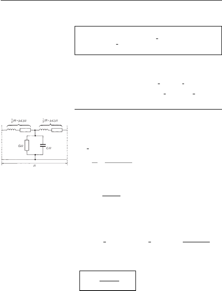
Let a very short length of line υl metres be as shown in Figure 44.4
comprising a single T-section. Each series arm impedance is
Z
1
D
1
2
R C jωLυl ohms, and the shunt arm impedance is
Z
2
D
1
Y
2
D
1
G C jωCυl
Figure 44.4
[i.e., from Chapter 25, the total admittance Y
2
is the sum of the admittance
of the two parallel arms, i.e., in this case, the sum of
Gυl and
1
1/jωC
υl]
From equation (41.1), page 760, the characteristic impedance Z
0
of a T-
section having in each series arm an impedance Z
1
and a shunt arm
impedance Z
2
is given by: Z
0
D
Z
1
2
C 2Z
1
Z
2
Hence the characteristic impedance of the section shown in Figure 44.4 is
Z
0
D
1
2
R C jωLυl
2
C 2
1
2
R C jωLυl
1
G C jωCυl
The term Z
1
2
involves υl
2
and, since υl is a very short length of line, υl
2
is negligible. Hence
Z
0
D
R C j!L
G C j!C
ohms
44.7
Transmission lines 877
If losses R and G are neglected, then
Z
0
D
p
.L=C/ ohms
44.8
Problem 7. Atransmissionlinehasthefollowingprimaryconstants:
resistance R D 15 #/loop km, inductance L D 3.4 mH/loop km,
conductance G D 3
µS/km and capacitance C D 10 nF/km. Deter-
mine the characteristic impedance of the line when the frequency is
2 kHz.
From equation (44.7),
characteristic impedance Z
0
D
R C jωL
G C jωC
ohms
R C jωL D 15 C j220003.4 ð 10
3
D 15 C j42.73# D 45.29
6
70.66
°
#
G C jωC D 3 ð 10
6
C j2200010 ð 10
9
D 3 C j125.6610
6
S D 125.7 ð 10
6
6
88.63
°
S
Hence Z
0
D
45.29
6
70.66
°
125.7 ð10
6
6
88.63
°
D
[0.360 ð 10
6
6
17.97
°
] #
i.e., characteristic impedance, Z
0
D 600
66
−8.99
°
Z
Propagation coefficient
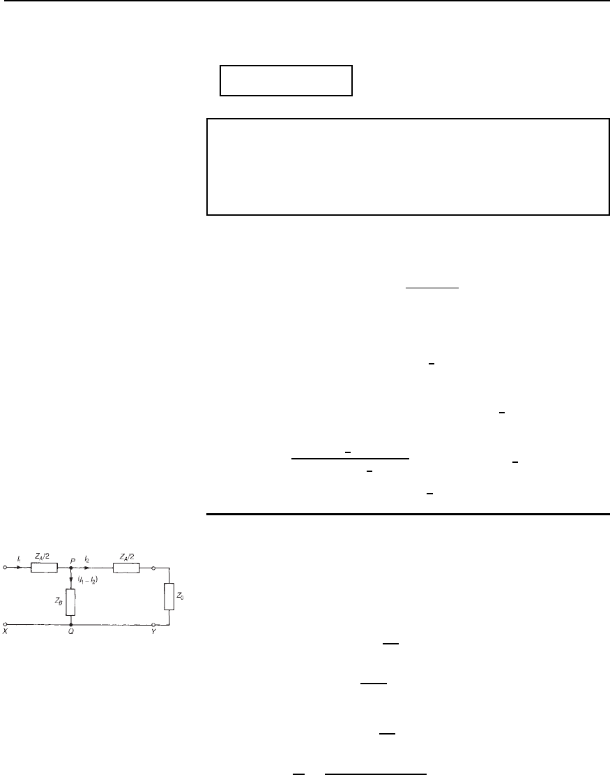
Figure 44.5 shows a T-section with the series arm impedances each
expressed as Z
A
/2 ohms per unit length and the shunt impedance as
Z
B
ohms per unit length. The p.d. between points P and Q is given by:
V
PQ
D I
1
I
2
Z
B
D I
2
Z
A
2
C Z
0
i.e., I
1
Z
B
I
2
Z
B
D
I
2
Z
A
2
C I
2
Z
0
Hence I
1
Z
B
D I
2
Z
B
C
Z
A
2
C Z
0
from which
I
1
I
2
D
Z
B
C Z
A
/2 C Z
0
Z
B
Figure 44.5
