Bird J. Electrical Circuit Theory and Technology
Подождите немного. Документ загружается.

888 Electrical Circuit Theory and Technology
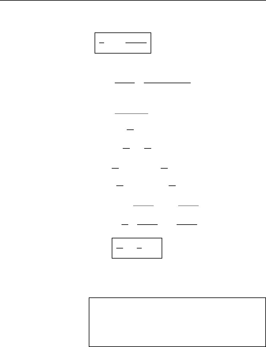
The ratio of the reflected current to the incident current is called the
reflection coefficient and is often given the symbol , i.e.,
I
r
I
i
= r =
Z
0
− Z
R
Z
0
Y Z
R
44.16
By similar reasoning to above an expression for the ratio of the reflected
to the incident voltage may be obtained. From above,
Z
R
D
V
i
C V
r
I
i
C I
r
D
V
i
C V
r
V
i
/Z
0
V
r
/Z
0
from equations (44.13) and (44.15),
i.e., Z
R
D
V
i
C V
r
V
i
V
r
/Z
0
Hence
Z
R
Z
0
V
i
V
r
D V
i
C V
r
from which,
Z
R
Z
0
V
i
Z
R
Z
0
V
r
D V
i
C V
r
Then
Z
R
Z
0
V
i
V
i
D V
r
C
Z
R
Z
0
V
r
and V
i
Z
R
Z
0
1
D V
r
1 C
Z
R
Z
0
Hence V
i
Z
R
Z
0
Z
0
D V
r
Z
0
C Z
R
Z
0
from which
V
r
V
i
D
Z
R
Z
0
Z
0
C Z
R
D
Z
0
Z
R
Z
0
C Z
R
44.17
Hence
V
r
V
i
D
I
r
I
i
Dr
44.18
Thus the ratio of the reflected to the incident voltage has the same magni-
tude as the ratio of reflected to incident current, but is of opposite sign.
From equations (44.16) and (44.17) it is seen that when Z
R
D Z
0
, D 0
and there is no reflection.
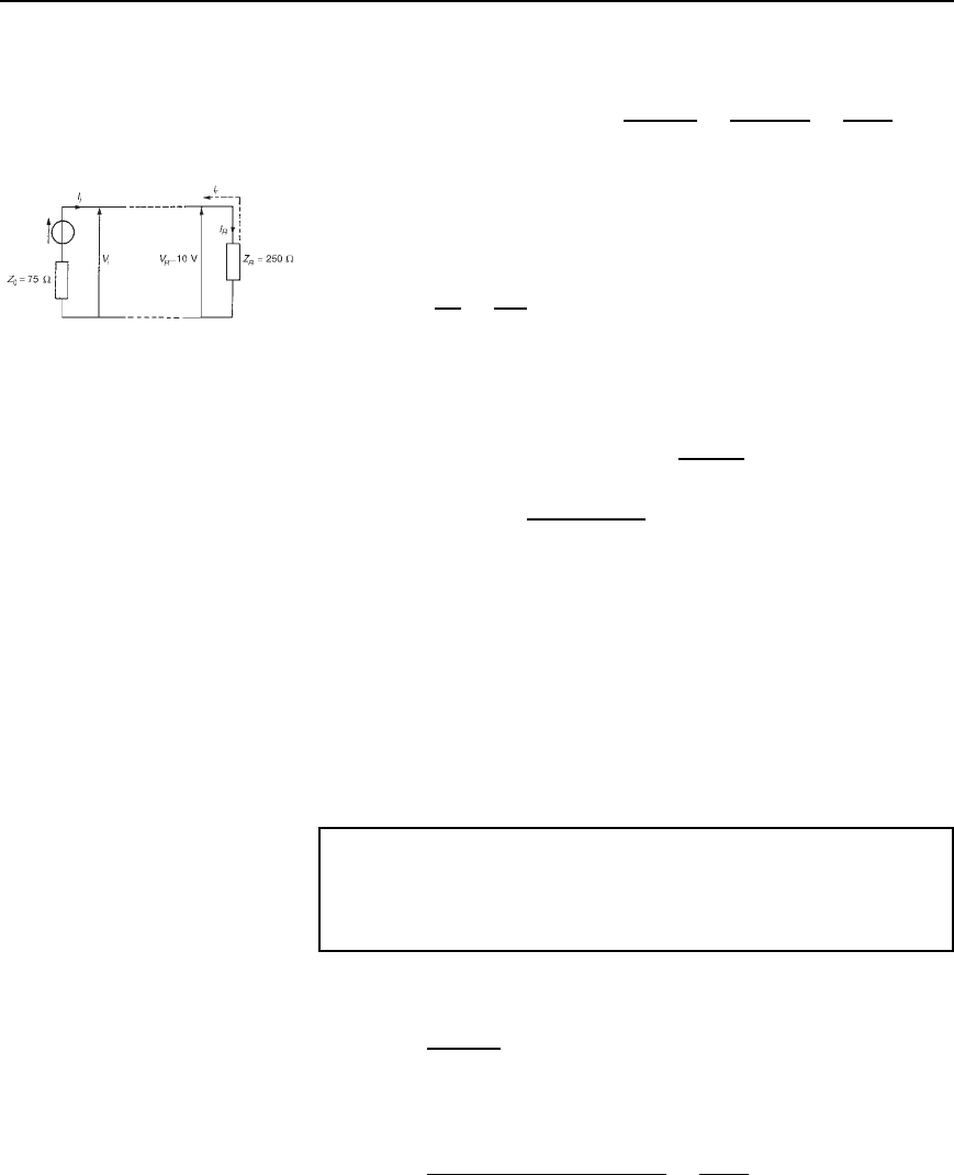
Problem 13. A cable which has a characteristic impedance of
75 # is terminated in a 250 # resistive load. Assuming that the
cable has negligible losses and the voltage measured across the
terminating load is 10 V, calculate the value of (a) the reflection
coefficient for the line, (b) the incident current, (c) the incident
voltage, (d) the reflected current, and (e) the reflected voltage.
Transmission lines 889
(a) From equation (44.16),
reflection coefficient, r D
Z
0
Z
R
Z
0
C Z
R
D
75 250
75 C 250
D
175
325
D
−0.538
(b) The circuit diagram is shown in Figure 44.9. Current flowing in the
terminating load,
I
R
D
V
R
Z
R
D
10
250
D 0.04 A
Figure 44.9
However, current I
R
D I
i
C I
r
. From equation (44.16), I
r
D I
i
Thus I
R
D I
i
C I
i
D I
i
1 C
from which incident current, I
i
D
I
R
1 C
D
0.04
1 C 0.538
D 0.0866 A or 86.6mA
(c) From equation (44.12),
incident voltage, V
i
D I
i
Z
0
D 0.086675 D 6.50 V
(d) Since I
R
D I
i
C I
r
reflected current, I
r
D I
R
I
i
D 0.04 0.0866
D
−0.0466 A or −46.6mA
(e) From equation (44.14),
reflected voltage, V
r
DI
r
Z
0
D0.046675 D 3.50 V
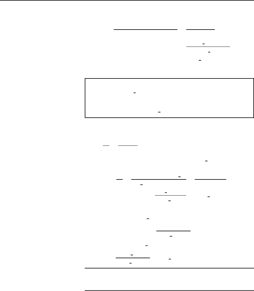
Problem 14. A long transmission line has a characteristic
impedance of 500 j40# and is terminated in an impedance of
(a) 500 Cj40# and (b) 600 C j20#. Determine the magnitude
of the reflection coefficient in each case.
(a) From equation (44.16), reflection coefficient,
D
Z
0
Z
R
Z
0
C Z
R
When Z
0
D 500 j40# and Z
R
D 500 C j40#
D
500 j40 500 C j40
500 j40 C 500 C j40
D
j80
1000
Dj0.08
Hence the magnitude of the reflection coefficient, jjD0.08
890 Electrical Circuit Theory and Technology
(b) When Z
0
D 500 j40# and Z
R
D 600 C j20#
D
500 j40 600 C j20
500 j40 C 600 C j20
D
100 j60
1100 j20
D
116.62
6
149.04
°
1100.18
6
1.04
°
D 0.106
6
148
°
Hence the magnitude of the reflection coefficient, jjD0.106
Problem 15. A loss-free transmission line has a characteristic
impedance of 500
6
0
°
# and is connected to an aerial of impedance
320 C j240#. Determine (a) the magnitude of the ratio of the
reflected to the incident voltage wave, and (b) the incident voltage
if the reflected voltage is 20
6
35
°
V
(a) From equation (44.17), the ratio of the reflected to the incident
voltage is given by:
V
r
V
i
D
Z
R
Z
0
Z
R
C Z
0
where Z
0
is the characteristic impedance 500
6
0
°
# and Z
R
is the
terminating impedance 320 C j240#.
Thus
V
r
V
i
D
320 C j240 500
6
0
°
500
6
0
°
C 320 Cj240
D
180 Cj240
820 C j240
D
300
6
126.87
°
854.4
6
16.31
°
D 0.351
6
110.56
°
Hence the magnitude of the ratio V
r
: V
i
is 0.351
(b) Since V
r
/V
i
D 0.351
6
110.56
°
,
incident voltage, V
i
D
V
r
0.351
6
110.56
°
Thus, when V
r
D 20
6
35
°
V,
V
i
D
20
6
35
°
0.351
6
110.56
°
D 57.0
66
−75.56
°
V
Further problems on the reflection coefficientmay be found in Section 44.9,
problems 14 to 16, page 899.
44.8 Standing waves and
the standing wave ratio
Consider a lossfree transmission line open-circuited at its termination. An
incident current waveform is completely reflected at the termination, and,
as stated in Section 44.7, the reflected current is of the same magnitude
as the incident current but is 180
°
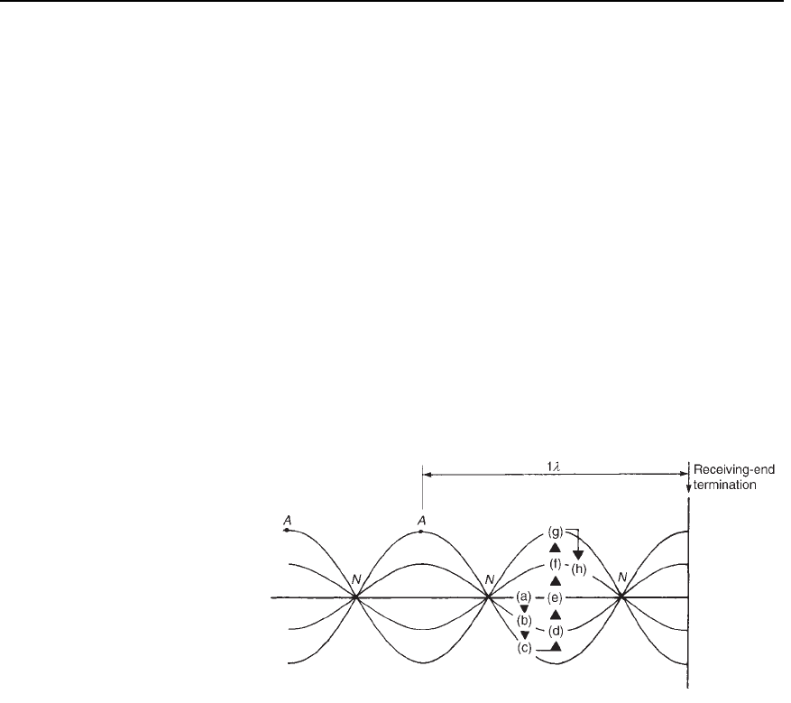
out of phase. Figure 44.10(a) shows
the incident and reflected current waveforms drawn separately (shown as
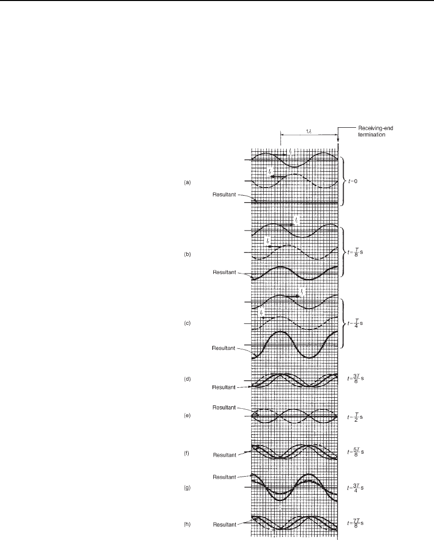
Transmission lines 891
I
i
moving to the right and I
r
moving to the left respectively) at a time
t D 0, with I
i
D 0 and decreasing at the termination.
The resultant of the two waves is obtained by adding them at inter-
vals. In this case the resultant is seen to be zero. Figures 44.10(b) and
(c) show the incident and reflected waves drawn separately as times
t D T/8 seconds and t D T/4, where T is the periodic time of the signal.
Again, the resultant is obtained by adding the incident and reflected wave-
forms at intervals. Figures 44.10(d) to (h) show the incident and reflected
Figure 44.10 Current waveforms on an open-circuited
transmission line
892 Electrical Circuit Theory and Technology
current waveforms plotted on the same axis, together with their resultant
waveform, at times t D 3T/8tot D 7T/8 at intervals of T/8.
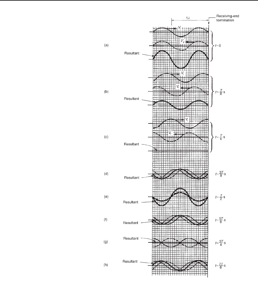
If the resultant waveforms shown in Figures 44.10(a) to (g) are super-
imposed one upon the other, Figure 44.11 results. (Note that the scale has
been increased for clarity.) The waveforms show clearly that waveform
(a) moves to (b) after T/8, then to (c) after a further period of T/8, then
to (d), (e), (f), (g) and (h) at intervals of T/8. It is noted that at any partic-
ular point the current varies sinusoidally with time, but the amplitude of
oscillation is different at different points on the line.
Whenever two waves of the same frequency and amplitude travelling in
opposite directions are superimposed on each other as above, interference
takes place between the two waves and a standing or stationary wave is
produced. The points at which the current is always zero are called nodes
(labelled N in Figure 44.11). The standing wave does not progress to the
left or right and the nodes do not oscillate. Those points on the wave
that undergo maximum disturbance are called antinodes (labelled A in
Figure 44.11). The distance between adjacent nodes or adjacent antinodes
is /2, where is the wavelength. A standing wave is therefore seen to be
a periodic variation in the vertical plane taking place on the transmission
line without travel in either direction.
Figure 44.11
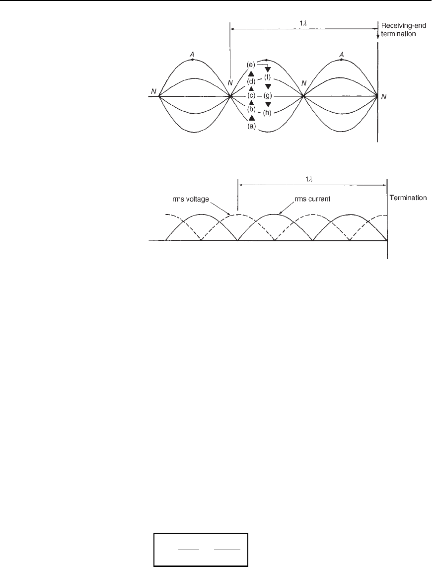
The resultant of the incident and reflected voltage for the open-circuit
termination may be deduced in a similar manner to that for current.
However, as stated in Section 44.7, when the incident voltage wave
reaches the termination it is reflected without phase change. Figure 44.12
shows the resultant waveforms of incident and reflected voltages at
intervals of t D T/8. Figure 44.13 shows all the resultant waveforms
of Figure 44.12(a) to (h) superimposed; again, standing waves are seen
to result. Nodes (labelled N) and antinodes (labelled A) are shown in
Figure 44.13 and, in comparison with the current waves, are seen to occur
90
°
out of phase.
If the transmission line is short-circuited at the termination, it is
the incident current that is reflected without phase change and the
incident voltage that is reflected with a phase change of 180
°
. Thus the
diagrams shown in Figures 44.10 and 44.11 representing current at an
Transmission lines 893
Figure 44.12 Voltage waveforms on an open-circuited transmission line
open-circuited termination may be used to represent voltage conditions
at a short-circuited termination and the diagrams shown in Figures 44.12
and 44.13 representing voltage at an open-circuited termination may be
used to represent current conditions at a short-circuited termination.
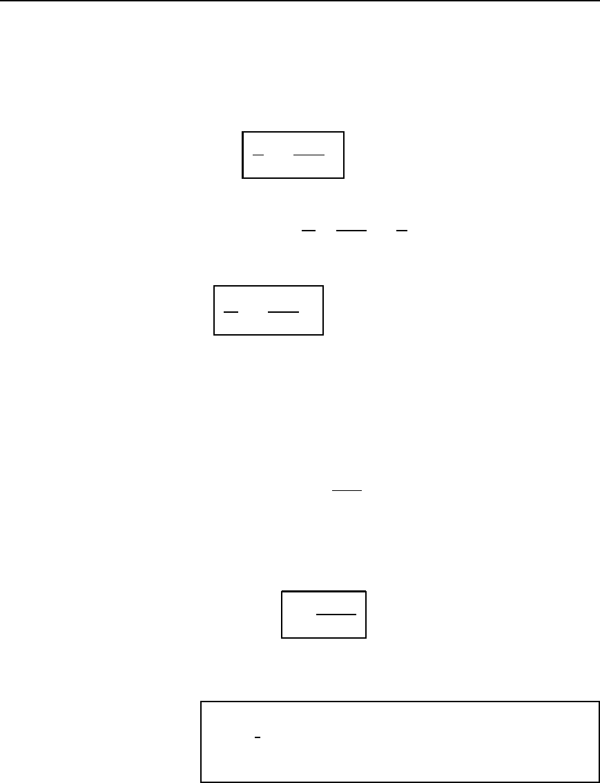
Figure 44.14 shows the rms current and voltage waveforms plotted
on the same axis against distance for the case of total reflection, deduced
894 Electrical Circuit Theory and Technology
Figure 44.13
Figure 44.14
from Figures 44.11 and 44.13. The rms values are equal to the amplitudes
of the waveforms shown in Figures 44.11 and 44.13, except that they
are each divided by
p
2 (since, for a sine wave, rms value D 1/
p
2 ð
maximum value). With total reflection, the standing-wave patterns of rms
voltage and current consist of a succession of positive sine waves with the
voltage node located at the current antinode and the current node located
at the voltage antinode. The termination is a current nodal point. The rms
values of current and voltage may be recorded on a suitable rms instru-
ment moving along the line. Such measurements of the maximum and
minimum voltage and current can provide a reasonably accurate indica-
tion of the wavelength, and also provide information regarding the amount
of reflected energy relative to the incident energy that is absorbed at the
termination, as shown below.
Standing-wave ratio
Let the incident current flowing from the source of a mismatched low-
loss transmission line be I
i
and the current reflected at the termination be
I
r
.IfI
MAX
is the sum of the incident and reflected current, and I
MIN
is
their difference, then the standing-wave ratio (symbol s) on the line is
defined as:
s D
I
MAX
I
MIN
D
I
i
C I
r
I
i
I
r
44.19
Transmission lines 895
Hence sI
i
I
r
D I
i
C I
r
sI
i
sI
r
D I
i
C I
r
sI
i
I
i
D sI
r
C I
r
I
i
s 1 D I
r
s C 1
i.e.,
I
r
I
i
D
s − 1
s Y 1
44.20
The power absorbed in the termination P
t
D I
i
2
Z
0
and the reflected power,
P
r
D I
r
2
Z
0
. Thus
P
r
P
t
D
I
r
2
Z
0
I
i
2
Z
0
D
I
r
I
i
2
Hence, from equation (44.20),
P
r
P
t
D
s − 1
s Y 1
2
44.21
Thus the ratio of the reflected to the transmitted power may be calculated
directly from the standing-wave ratio, which may be calculated from
measurements of I
MAX
and I
MIN
. When a transmission line is properly
terminated there is no reflection, i.e., I
r
D 0, and from equation (44.19)
the standing-wave ratio is 1. From equation (44.21), when s D 1, P
r
D 0,
i.e., there is no reflected power. In practice, the standing-wave ratio is
kept as close to unity as possible.
From equation (44.16), the reflection coefficient, D I
r
/I
i
Thus, from
equation (44.20), jjD
s 1
s C 1
Rearranging gives: jjs C 1 D s 1
jjs CjjDs 1
1 CjjDs1 jj
from which
s D
1 Y jrj
1 − jrj
44.22
Equation (44.22) gives an expression for the standing-wave ratio in terms
of the magnitude of the reflection coefficient.
Problem 16. A transmission line has a characteristic impedance
of 600
6
0
°
# and negligible loss. If the terminating impedance of
the line is 400 Cj250#, determine (a) the reflection coefficient
and (b) the standing-wave ratio.
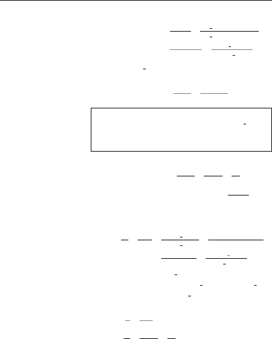
896 Electrical Circuit Theory and Technology
(a) From equation (44.16),
reflection coefficient, D
Z
0
Z
R
Z
0
C Z
R
D
600
6
0
°
400 Cj250
600
6
0
°
C 400 Cj250
D
200 j250
1000 C j250
D
320.16
6
51.34
°
1030.78
6
14.04
°
Hence r D 0.3106
66
− 65.38
°
(b) From above, jjD0.3106. Thus from equation (44.22),
standing-wave ratio, s D
1 Cjj
1 jj
D
1 C 0.3106
1 0.3106
D 1.901
Problem 17. A low-loss transmission line has a mismatched load
such that the reflection coefficient at the termination is 0.2
6
120
°
.
The characteristic impedance of the line is 80 #. Calculate (a) the
standing-wave ratio, (b) the load impedance, and (c) the incident
current flowing if the reflected current is 10 mA.
(a) From equation (44.22),
standing-wave ratio, s D
1 Cjj
1 jj
D
1 C 0.2
1 0.2
D
1.2
0.8
D 1.5
(b) From equation (44.16) reflection coefficient, D
Z
0
Z
R
Z
0
C Z
R
Rearranging gives: Z
0
C Z
R
D Z
0
Z
R
,
from which Z
R
C 1 D Z
0
1
and
Z
R
Z
0
D
1
1 C
D
1 0.2
6
120
°
1 C 0.2
6
120
°
D
1 0.10 j0.173
1 C 0.10 j0.173
D
1.10 Cj0.173
0.90 j0.173
D
1.1135
6
8.94
°
0.9165
6
10.88
°
D 1.215
6
19.82
°
Hence load impedance Z
R
D Z
0
1.215
6
19.82
°
D801.215
6
19.82
°
D 97.2
66
19.82
°
Z or .91.4 Y j33.0/Z
(c) From equation (44.20),
I
r
I
i
D
s 1
s C 1
Hence
10
I
i
D
1.5 1
1.5 C 1
D
0.5
2.5
D 0.2
Thus the incident current, I
i
D 10/0.2 D 50 mA

Transmission lines 897
Problem 18. The standing-wave ratio on a mismatched line is
calculated as 1.60. If the incident power arriving at the termina-
tion is 200 mW, determine the value of the reflected power.
From equation (44.21),
P
r
P
t
D
s 1
s C 1
2
D
1.60 1
1.60 C1
2
D
0.60
2.60
2
D 0.0533
Hence the reflected power, P
r
D 0.0533P
t
D 0.0533200
D 10.66 mW
Further problems on the standing wave ratio may be found in Section 44.9
following, problems 17 to 21, page 899.
44.9 Further problems
on transmission lines
Phase delay, wavelength and velocity of propagation
1 A parallel-wire air-spaced line has a phase-shift of 0.03 rad/km.
Determine (a) the wavelength on the line, and (b) the speed of trans-
mission of a signal of frequency 1.2 kHz.
[(a) 209.4 km (b) 251.3 ð 10
6
m/s]
2 A transmission line has an inductance of 5
µH/m and a capacitance of
3.49 pF/m. Determine, for an operating frequency of 5 kHz, (a) the
phase delay, (b) the wavelength on the line and (c) the velocity of
propagation of the signal in metres per second.
[(a) 0.131 rad/km (b) 48 km (c) 240 ð 10
6
m/s]
3 An air-spaced transmission line has a capacitance of 6.0 pF/m and the
velocity of propagation of a signal is 225 ð10
6
m/s. If the operating
frequency is 20 kHz, determine (a) the inductance per metre, (b) the
phase delay, and (c) the wavelength on the line.
[(a) 3.29
µH/m (b) 0.558 ð 10
3
rad/m (c) 11.25 km]
Current and voltage relationships
4 When the working frequency of a cable is 1.35 kHz, its attenuation
is 0.40 Np/km and its phase-shift is 0.25 rad/km. The sending-end
voltage and current are 8.0 V rms and 10.0 mA rms. Determine the
voltage and current at a point 25 km down the line, assuming that
the termination is equal to the characteristic impedance of the line.
[V
R
D 0.363
6
6.25 mV or 0.363
6
1.90
°
mV
I
R
D 0.454
6
6.25 µAor0.454
6
1.90
°
µA]
5 A transmission line 8 km long has a characteristic impedance
600
6
30
°
#. At a particular frequency the attenuation coefficient of
the line is 0.4 Np/km and the phase-shift coefficient is 0.20 rad/km.
