Bird J. Electrical Circuit Theory and Technology
Подождите немного. Документ загружается.

Th´evenin’s and Norton’s theorems 579
Note that, to find the current in the capacitor, only the capacitor
need have been initially removed from the circuit. However,
removing each of the components from the branch through
which the current is required will often result in a simpler
solution.
(ii) From Figure 33.13,
current I
1
D
200
6
0
°
5000 C 20000
D 8mA
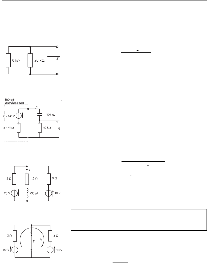
The open-circuit e.m.f. E is equal to the p.d. across the 20 k
resistor, i.e.
E D 8 ð 10
3
20 ð 10
3
D 160 V.
(iii) Removing the 200
6
0
°
V source gives the network shown in
Figure 33.14.
Figure 33.14
The impedance, z, ‘looking in’ at the open-circuited terminals
is given by
z D
5 ð 20
5 C 20
k D 4kZ
Figure 33.15
(iv) The Th
´
evenin equivalent circuit is shown in Figure 33.15,
where current i
L
is given by
i
L
D
E
Z
L
C z
D
160
150 j120 ð 10
3
C 4 ð 10
3
D
160
195.23 ð 10
3
6
37.93
°
D 0.82
6
37.93
°
mA
Thus the current flowing in the capacitor is 0.82 mA.
(b) P.d. across the 150 k resistor,
V
0
D i
L
R D 0.82 ð 10
3
150 ð 10
3
D 123 V
Figure 33.16
Problem 2. Determine, for the network shown in Figure 33.16,
the value of current I. Each of the voltage sources has a frequency
of 2 kHz.
(i) The impedance through which current I is flowing is initially
removed from the network, as shown in Figure 33.17.
(ii) From Figure 33.17,
current, I
1
D
20 10
2 C 3
D 2A
Figure 33.17

580 Electrical Circuit Theory and Technology
Figure 33.18
Hence the open circuit e.m.f. E D 20 I
1
2 D 20 22 D 16 V.
(Alternatively, E D 10 C I
1
3 D 10 C 23 D 16 V.)
(iii) When the sources of e.m.f. are removed from the circuit, the
impedance, z, ‘looking in’ at the break is given by
z D
2 ð 3
2 C 3
D 1.2 Z
(iv) The Th
´
evenin equivalent circuit is shown in Figure 33.18, where
inductive reactance,
X
L
D 2fL D 22000235 ð 10
6
D 2.95
Hence current
I D
16
1.2 C 1.5 Cj2.95
D
16
4.0
6
47.53
°
D 4.0
66
−47.53
°
A or .2.70 − j2.95/ A
Problem 3. Use Th
´
evenin’s theorem to determine the power dissi-
pated in the 48 resistor of the network shown in Figure 33.19.
Figure 33.19
The power dissipated by a current I flowing through a resistor R is given
by I
2
R, hence initially the current flowing in the 48 resistor is required.
(i) The 48 C j144 impedance is initially removed from the network
as shown in Figure 33.20.
(ii) From Figure 33.20,
current, i D
50
6
0
°
300 j400
D 0.1
6
53.13
°
A
Figure 33.20
Hence the open-circuit voltage
E D i300 D 0.1
6
53.13
°
300 D 30
66
53.13
°
V
(iii) When the 50
6
0
°
V source shown in Figure 33.20 is removed, the
impedance, z, is given by
z D
j400300
300 j400
D
400
6
90
°
300
500
6
53.13
°
D 240
6
36.87
°
or .192 − j144/Z
(iv) The Th
´
evenin equivalent circuit is shown in Figure 33.21 connected
to the 48 C j144 load.
Current I D
30
6
53.13
°
192 j144 C 48 C j144
D
30
6
53.13
°
240
6
0
°
D 0.125
6
53.13
°
A
Figure 33.21
Th´evenin’s and Norton’s theorems 581
Hence the power dissipated in the 48 Z resistor
D I
2
R D 0.125
2
48 D 0.75 W
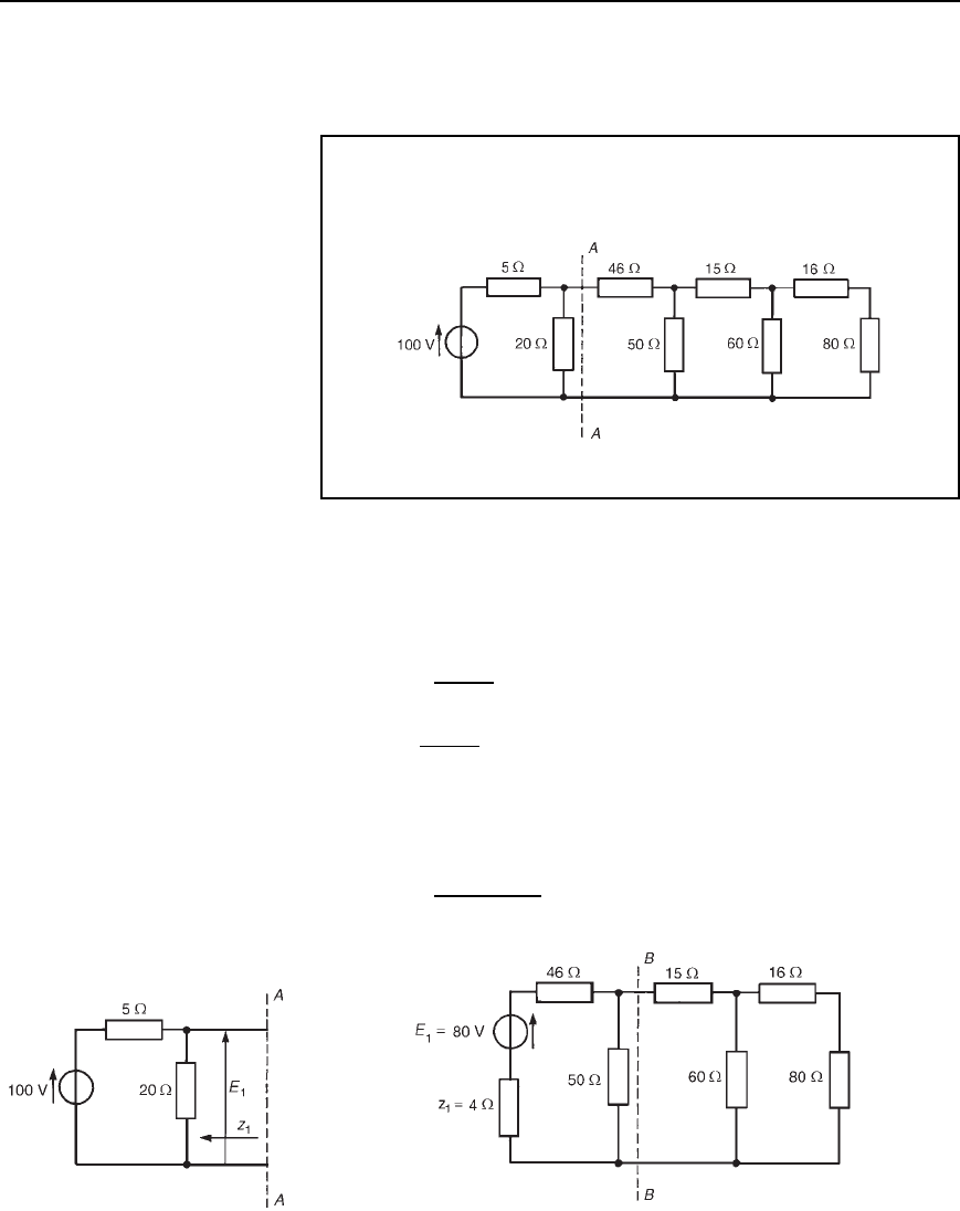
Problem 4. For the network shown in Figure 33.22, use
Th
´
evenin’s theorem to determine the current flowing in the 80
resistor.
Figure 33.22
One method of analysing a multi-branch network as shown in
Figure 33.22 is to use Th
´
evenin’s theorem on one part of the network
at a time. For example, the part of the circuit to the left of AA may be
reduced to a Th
´
evenin equivalent circuit.
From Figure 33.23,
E
1
D
20
20 C 5
100 D 80 V, by voltage division
and z
1
D
20 ð 5
20 C5
D 4
Thus the network of Figure 33.22 reduces to that of Figure 33.24. The
part of the network shown in Figure 33.24 to the left of BB may be
reduced to a Th
´
evenin equivalent circuit, where
E
2
D
50
50 C 46 C 4
80 D 40 V
Figure 33.23 Figure 33.24
570 Electrical Circuit Theory and Technology
and current I
6
D
6 C j8
3 C j4 C 6 C j8
0.062 C j0.964
D 0.041 C j0.643A
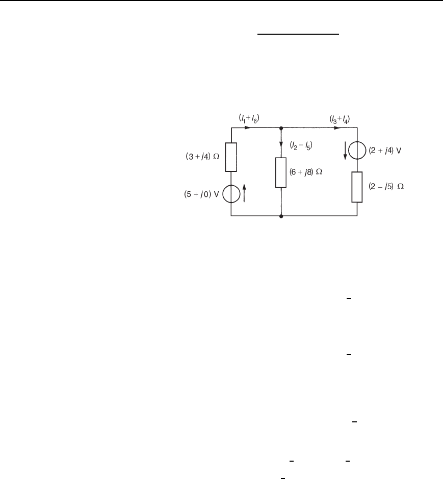
(v) If Figure 32.22 is superimposed on Figure 32.20, the resultant
currents are as shown in Figure 32.24.
Figure 32.24
(vi) Resultant current flowing from (5 C j0)V source is given by
I
1
C I
6
D 0.614 j0.025 C 0.041 C j0.643
D .0.573 Y j0.618/A or 0.843
66
47.16
°
A
Resultant current flowing from (2 C j4)V source is given by
I
3
C I
4
D 0.622 C j0.363 C 0.062 C j0.964
D .0.560 Y j1.327/A or 1.440
66
67.12
°
A
Resultant current flowing through the 6 C j8 impedance is
given by
I
2
I
5
D 0.00731 j0.388 0.0207 C j0.321
D .0.0134
− j0.709/A or 0.709
66
−88.92
°
A
(b) Voltage across 6 C j8 impedance is given by
I
2
I
5
6 C j8 D 0.709
6
88.92
°
10
6
53.13
°
D 7.09
6
35.79
°
V
i.e., the magnitude of the voltage across the 6 C j8 impedance
is 7.09 V
(c) Total active power P delivered to the network is given by
P D E
1
I
1
C I
6
cos
1
C E
2
I
3
C I
4
cos
2
where
1
is the phase angle between E
1
and (I
1
C I
6
)and
2
is the
phase angle between E
2
and (I
3
C I
4
), i.e.,
582 Electrical Circuit Theory and Technology
Figure 33.25
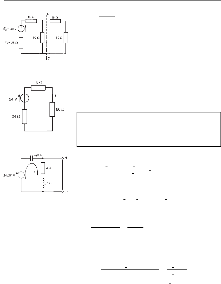
and z
2
D
50 ð 50
50 C50
D 25
Thus the original network reduces to that shown in Figure 33.25.
The part of the network shown in Figure 33.25 to the left of CC may be
reduced to a Th
´
evenin equivalent circuit, where
E
3
D
60
60 C 25 C 15
40 D 24 V
and z
3
D
6040
60 C 40
D 24
Thus the original network reduces to that of Figure 33.26, from which
the current in the 80 Z resistor is given by
I D
24
80 C 16 C 24
D 0.20 A
Figure 33.26
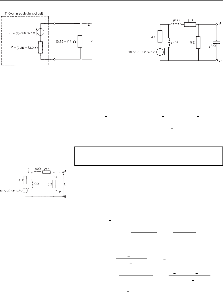
Problem 5. Determine the Th
´
evenin equivalent circuit with
respect to terminals AB of the circuit shown in Figure 33.27.
Hence determine (a) the magnitude of the current flowing in a
3.75 C j11 impedance connected across terminals AB, and
(b) the magnitude of the p.d. across the 3.75 C j11 impedance.
Figure 33.27
Current I
1
shown in Figure 33.27 is given by
I
1
D
24
6
0
°
4 C j3 j3
D
24
6
0
°
4
6
0
°
D 6
6
0
°
A
The Th
´
evenin equivalent voltage, i.e., the open-circuit voltage across
terminals AB, is given by
E D I
1
4 C j3 D 6
6
0
°
5
6
36.87
°
D 30
66
36.87
°
V
When the 24
6
0
°
V source is removed, the impedance z ‘looking in’ at
AB is given by
z D
4 C j3j3
4 C j3 j3
D
9 j12
4
D .2.25
− j3.0/Z
Thus the Th
´
evenin equivalent circuit is as shown in Figure 33.28.
(a) When a 3.75 C j11 impedance is connected across terminals AB,
the current I flowing in the impedance is given by
I D
30
6
36.87
°
3.75 C j11 C 2.25 j3.0
D
30
6
36.87
°
10
6
53.13
°
D 3
6
16.26
°
A
Th´evenin’s and Norton’s theorems 583
Figure 33.28 Figure 33.29
Hence the current flowing in the .3.75 Y j11/Z impedance
is3A.
(b) P.d. across the 3.75 Cj11 impedance is given by
V D 3
6
16.26
°
3.75 C j11 D 3
6
16.26
°
11.62
6
71.18
°
D 34.86
6
54.92
°
V
Hence the magnitude of the p.d. across the impedance is 34.9 V.
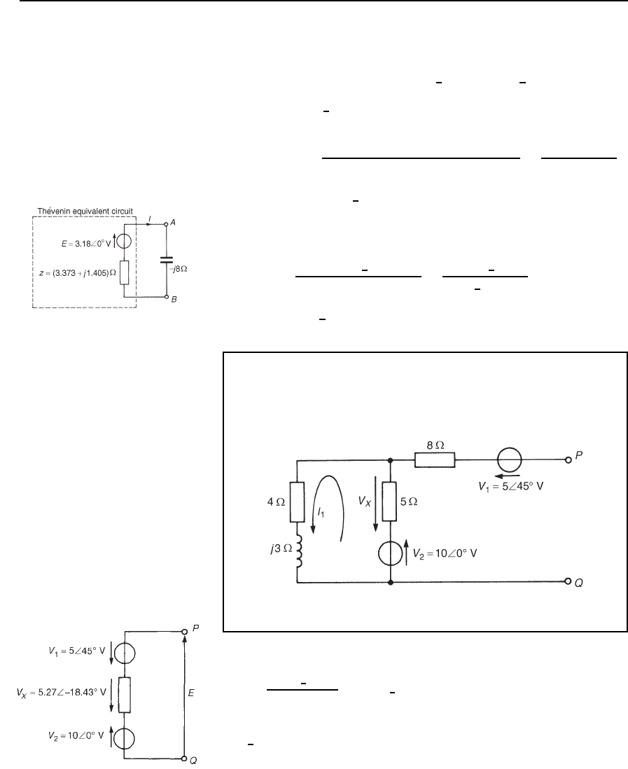
Problem 6. Use Th
´
evenin’s theorem to determine the current
flowing in the capacitor of the network shown in Figure 33.29.
(i) The capacitor is removed from branch AB, as shown in
Figure 33.30.
(ii) The open-circuit voltage, E, shown in Figure 33.30, is given by
I
2
5. I
2
may be determined by current division if I
1
is known.
(Alternatively, E may be determined by the method used in
problem 4.)
Figure 33.30
Current I
1
D V/Z, where Z is the total circuit impedance and
V D 16.55
6
22.62
°
V.
Impedance, Z D 4 C
j28 Cj6
j2 C 8 C j6
D 4 C
12 C j16
8 C j8
D 4.596
6
22.38
°
Hence I
1
D
16.55
6
22.62
°
4.596
6
22.38
°
D 3.60
6
45
°
A
and I
2
D
j2
j2 C 3 C j6 C 5
I
1
D
2
6
90
°
3.60
6
45
°
11.314
6
45
°
D 0.636
6
0
°
A
584 Electrical Circuit Theory and Technology
(An alternative method of finding I
2
is to use Kirchhoff’s laws or
mesh-current or nodal analysis on Figure 33.30.)
Hence E D I
2
5 D 0.636
6
0
°
5 D 3.18
66
0
°
V
(iii) If the 16.55
6
22.62
°
V source is removed from Figure 33.30, the
impedance, z, ‘looking in’ at AB is given by
z D
5[4 ðj2/4 C j2 C 3 C j6]
5 C [4 ð j2/4 C j2 C 3 C j6]
D
53.8 C j7.6
8.8 C j7.6
i.e. z D 3.654
6
22.61
°
or .3.373 Y j1.405/Z
(iv) The Th
´
evenin equivalent circuit is shown in Figure 33.31, where
the current flowing in the capacitor, I, is given by
I D
3.18
6
0
°
3.373 C j1.405 j8
D
3.18
6
0
°
7.408
6
62.91
°
D 0.43
66
62.91
°
A in the direction from A to B
Figure 33.31
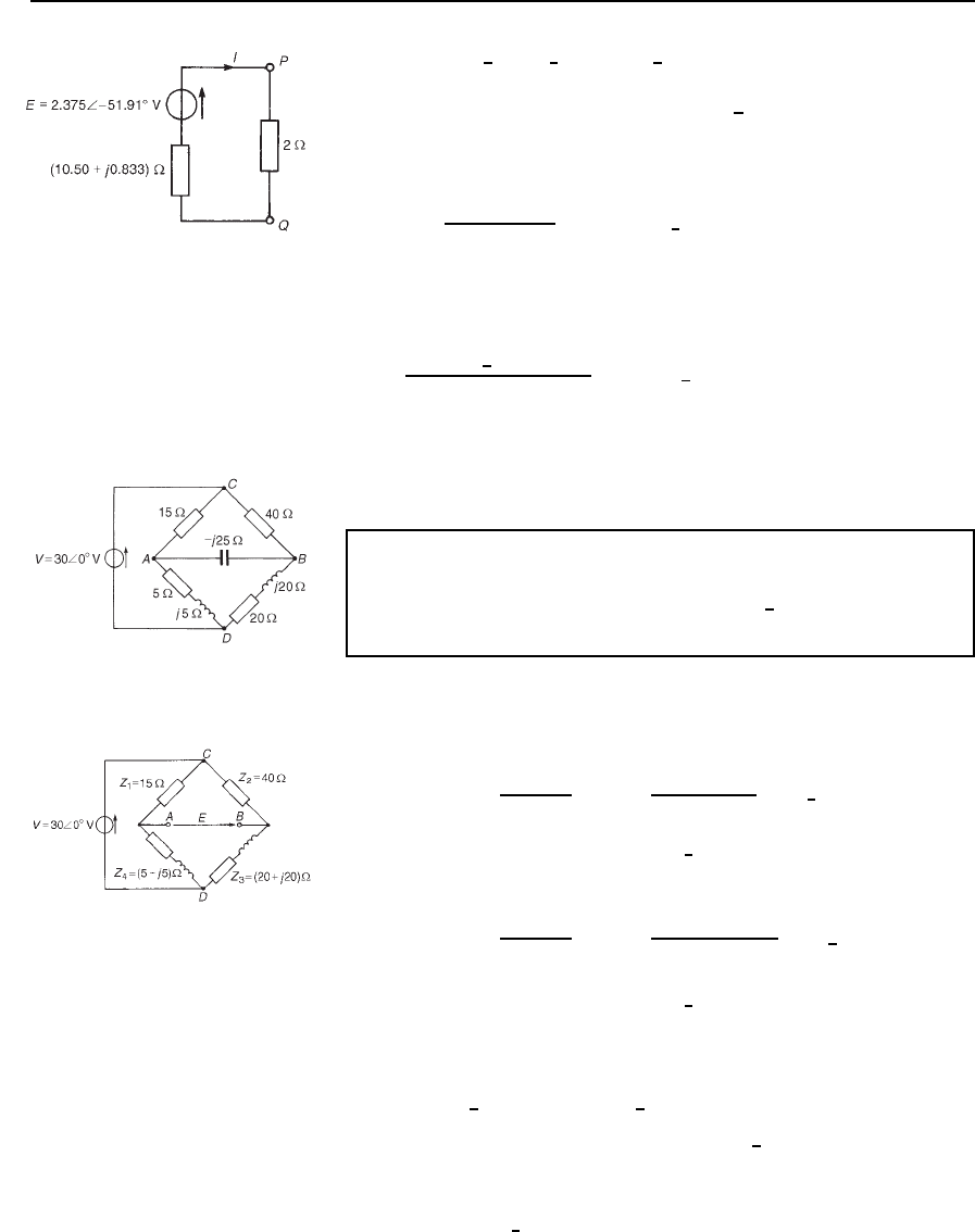
Problem 7. For the network shown in Figure 33.32, derive the
Th
´
evenin equivalent circuit with respect to terminals PQ, and
hence determine the power dissipated by a 2 resistor connected
across PQ.
Figure 33.32
Current I
1
shown in Figure 33.32 is given by
I
1
D
10
6
0
°
5 C 4 Cj3
D 1.054
6
18.43
°
A
Hence the voltage drop across the 5 resistor is given by V
X
D I
1
5 D
5.27
6
18.43
°
V, and is in the direction shown in Figure 33.32, i.e., the
direction opposite to that in which I
1
is flowing.
The open-circuit voltage E across PQ is the phasor sum of V
1
, V
x
and
V
2
, as shown in Figure 33.33.
Figure 33.33
Th´evenin’s and Norton’s theorems 585
Figure 33.34
Thus E D 10
6
0
°
5
6
45
°
5.27
6
18.43
°
D 1.465 j1.869Vor2.375
66
−51.91
°
V
The impedance, z, ‘looking in’ at terminals PQ with the voltage sources
removed is given by
z D 8 C
54 C j3
5 C 4 Cj3
D 8 C2.635
6
18.44
°
D .10.50 Y j0.833/Z
The Th
´
evenin equivalent circuit is shown in Figure 33.34 with the 2
resistance connected across terminals PQ.
The current flowing in the 2 resistance is given by
I D
2.375
6
51.91
°
10.50 C j0.833 C 2
D 0.1896
6
55.72
°
A
The power P dissipated in the 2 resistor is given by
P D I
2
R D 0.1896
2
2 D 0.0719 W 72 mW, correct to two
significant figures.
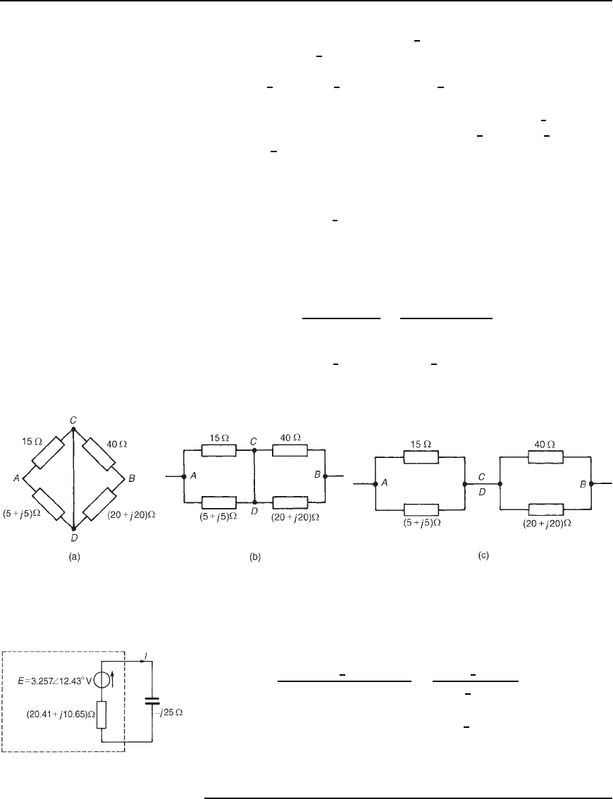
Problem 8. For the a.c. bridge network shown in Figure 33.35,
determine the current flowing in the capacitor, and its direction,
by using Th
´
evenin’s theorem. Assume the 30
6
0
°
V source to have
negligible internal impedance.
Figure 33.35
(i) The j25 capacitor is initially removed from the network, as
shown in Figure 33.36.
(ii) P.d. between A and C,
V
AC
D
Z
1
Z
1
C Z
4
V D
15
15 C 5 C j5
30
6
0
°
D 21.83
6
14.04
°
V
Figure 33.36
P.d. between B and C,
V
BC
D
Z
2
Z
2
C Z
3
V D
40
40 C 20 C j20
30
6
0
°
D 18.97
6
18.43
°
V
Assuming that point A is at a higher potential than point B, then
the p.d. between A and B is
21.83
6
14.04
°
18.97
6
18.43
°
D 3.181 C j0.701Vor3.257
6
12.43
°
V,
i.e., the open-circuit voltage across AB is given by
E D 3.257
6
12.43
°
V.
586 Electrical Circuit Theory and Technology
Point C is at a potential of 30
6
0
°
V. Between C and A is a volt
drop of 21.83
6
14.04
°
V. Hence the voltage at point A is
30
6
0
°
21.83
6
14.04
°
D 10.29
66
30.98
°
V
Between points C and B is a voltage drop of 18.97
6
18.43
°
V.
Hence the voltage at point B is 30
6
0
°
18.97
6
18.43
°
D
13.42
66
26.55
°
V.
Since the magnitude of the voltage at B is higher than at A, current
must flow in the direction B to A.
(iii) Replacing the 30
6
0
°
V source with a short-circuit (i.e., zero internal
impedance) gives the network shown in Figure 33.37(a). The
network is shown redrawn in Figure 33.37(b) and simplified in
Figure 33.37(c). Hence the impedance, z, ‘looking in’ at terminals
AB is given by
z D
155 C j5
15 C 5 Cj5
C
4020 C j20
40 C 20 C j20
D 5.145
6
30.96
°
C 17.889
6
26.57
°
i.e., z D 20.41 C j10.65
Figure 33.37
(iv) The Th
´
evenin equivalent circuit is shown in Figure 33.38, where
current I is given by
I D
3.257
6
12.43
°
20.41 C j10.65 j25
D
3.257
6
12.43
°
24.95
6
35.11
°
D 0.131
6
47.54
°
A
Thus a current of 131 mA flows in the capacitor in a direction
fromBtoA.
Figure 33.38
Th´evenin’s and Norton’s theorems 587
Further problems on Th´evenin’s theorem may be found in Section 33.5,
problems 1 to 10, page 598.
33.3 Norton’s theorem
A source of electrical energy can be represented by a source of e.m.f. in
series with an impedance. In Section 33.2, the Th
´
evenin constant-voltage
source consisted of a constant e.m.f. E, which may be alternating or direct,
in series with an internal impedance, z. However, this is not the only form
of representation. A source of electrical energy can also be represented by
a constant-current source, which may be alternating or direct, in parallel
with an impedance. It is shown in Section 33.4 that the two forms are in
fact equivalent.
Norton’s theorem states:
‘The current that flows in any branch ofa network is the same as that which
would flow in the branch if it were connected across a source of electrical
energy, the short-circuit current of which is equal to the current that would
flow in a short-circuit across the branch, and the internal impedance of
which is equal to the impedance which appears across the open-circuited
branch terminals.’
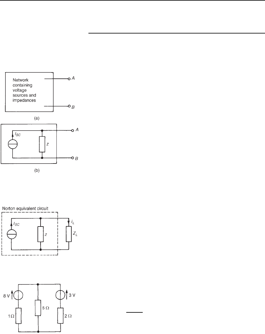
The above statement simply means that any linear active network
with output terminals AB, as shown in Figure 33.39(a), can be replaced
by a current source in parallel with an impedance z as shown in
Figure 33.39(b). The equivalent current source I
SC
(note the symbol in
Figure 33.39(b) as per BS 3939:1985) is the current through a short-circuit
applied to the terminals of the network. The impedance z is the equivalent
impedance of the network at the terminals AB when all internal sources of
e.m.f. are made zero. Figure 33.39(b) is known as the Norton equivalent
circuit, and was initially introduced in Section 13.7, page 181 for d.c.
networks.
Figure 33.39 The Norton
equivalent circuit
The following four-step procedure may be adopted when determining
the current flowing in an impedance Z
L
of a branch AB of an active
network, using Norton’s theorem:
(i) short-circuit branch AB;
(ii) determine the short-circuit current I
SC
;
(iii) remove each source of e.m.f. and replace it by its internal impedance
(or, if a current source exists, replace with an open circuit), then
determine the impedance, z, ‘looking in’ at a break made between
A and B;
(iv) determine the value of the current i
L
flowing in impedance Z
L
from
the Norton equivalent network shown in Figure 33.40, i.e.,
i
L
D
z
Z
L
C z
I
SC
Figure 33.40
A simple d.c. network (Figure 33.41) serves to demonstrate how the above
procedure is applied to determine the current flowing in the 5 resistance
by using Norton’s theorem:
Figure 33.41
