Bird J. Electrical Circuit Theory and Technology
Подождите немного. Документ загружается.

568 Electrical Circuit Theory and Technology
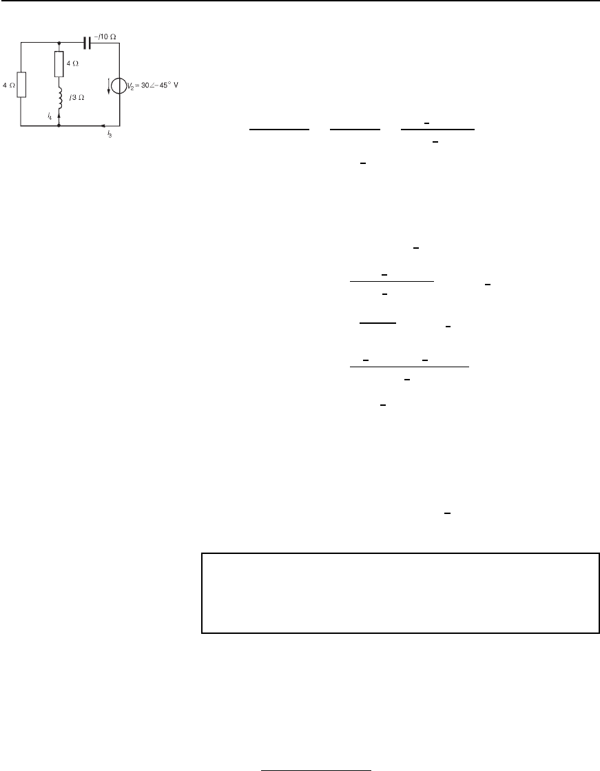
Figure 32.18
(iii) The original network is redrawn with V
1
removed, as shown in
Figure 32.18.
(iv) Currents I
3
and I
4
are shown in Figure 32.18. From Figure 32.18,
4 in parallel with 4 Cj3 gives an equivalent impedance of
44 C j3
4 C 4 C j3
D
16 C j12
8 C j3
D
20
6
36.87
°
8.544
6
20.56
°
D 2.341
6
16.31
°
or 2.247 Cj0.657
Total impedance of Figure 32.18 is
2.247 C j0.657 j10 D 2.247 j9.343 or
9.609
6
76.48
°
Hence current I
3
D
30
6
45
°
9.609
6
76.48
°
D 3.122
6
31.48
°
A
and current I
4
D
4
8 C j3
3.122
6
31.48
°
D
4
6
0
°
3.122
6
31.48
°
8.544
6
20.56
°
D 1.462
6
10.92
°
Aor1.436 Cj0.277A
(v) If the network of Figure 32.18 is superimposed on the network
of Figure 32.17, it can be seen that the current in the 4 Cj3
impedance is given by I
2
I
4
(vi) I
2
I
4
D 3.588 C j0.692 1.436 C j0.277
D .2.152 Y j0.415/A or 2.192
66
10.92
°
A,
flowing from AtoBin Figure 32.16.
Problem 4. For the a.c. network shown in Figure 32.19 determine,
using the superposition theorem, (a) the current in each branch,
(b) the magnitude of the voltage across the 6 Cj8 impedance,
and (c) the total active power delivered to the network.
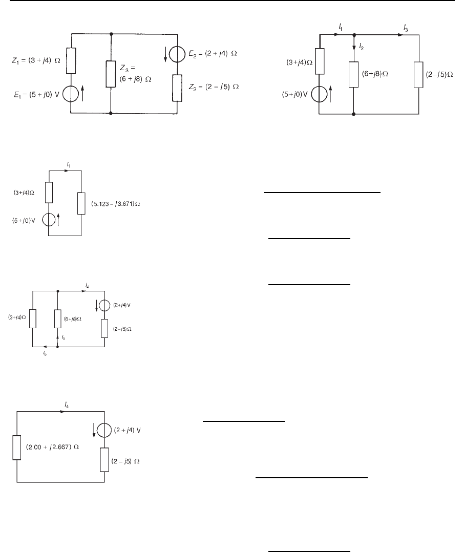
(a) (i) The original network is redrawn with E
2
removed, as shown in
Figure 32.20.
(ii) Currents I
1
, I
2
and I
3
are labelled as shown in Figure 32.20.
From Figure 32.20, 6 C j8 in parallel with 2 j5 gives
an equivalent impedance of
6 C j82 j5
6 C j8 C 2 j5
D 5.123 j3.671
The superposition theorem 569
Figure 32.19 Figure 32.20
From the equivalent network of Figure 32.21,
current I
1
D
5 C j0
3 C j4 C 5.123 j3.671
D 0.614 j0.025A
current I
2
D
2 j5
6 C j8 C 2 j5
0.614 j0.025
D 0.00731 j0.388A
and current I
3
D
6 C j8
6 C j8 C 2 j5
0.614 j0.025
D 0.622 C j0.363A
Figure 32.21
(iii) The original network is redrawn with E
1
removed, as shown in
Figure 32.22.
Figure 32.22
(iv) Currents I
4
, I
5
and I
6
are shown labelled in Figure 32.22 with I
4
flowing away from the positive terminal of the 2 C j4V source.
From Figure 32.22, 3 C j4 in parallel with 6 C j8 gives
an equivalent impedance of
3 C j46 C j8
3 C j4 C 6 C j8
D 2.00 C j2.667
From the equivalent network of Figure 32.23,
current I
4
D
2 C j4
2.00 C j2.667 C 2 j5
D 0.062 C j0.964A
Figure 32.23
From Figure 32.22,
current I
5
D
3 C j4
3 C j4 C 6 C j8
0.062 C j0.964
D 0.0207 C j0.321A
The superposition theorem 571
P D 50.843 cos47.16
°
0
°
C
2
2
C 4
2
1.440 cos
67.12
°
arctan
4
2
D 2.866 C 6.427 D 9.293 W
D 9.3W, correct to one dec. place.
(This value may be checked since total active power dissipated is
given by:
P D I
1
C I
6
2
3 C I
2
I
5
2
6 C I
3
C I
4
2
2
D 0.843
2
3 C 0.709
2
6 C 1.440
2
2
D 2.132 C 3.016 C 4.147 D 9.295 W
D 9.3W,correct to one dec. place.
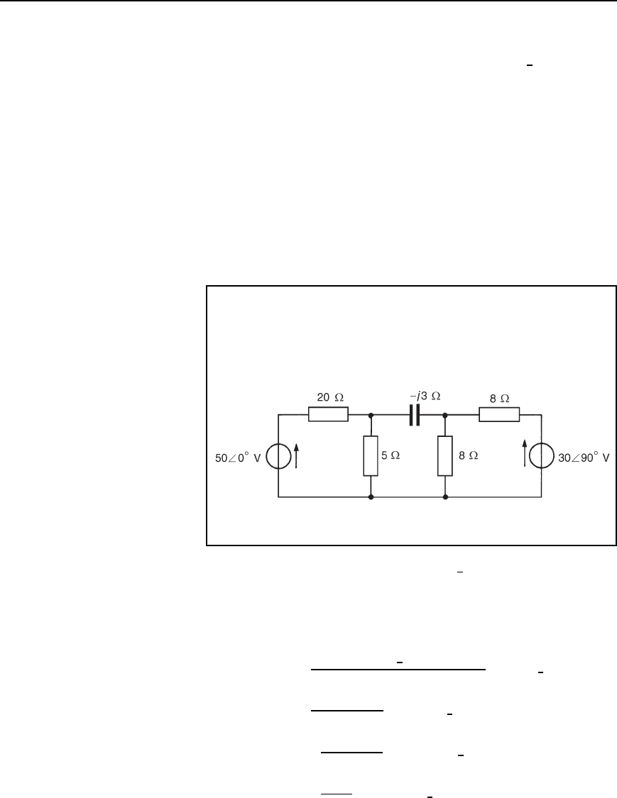
Problem 5. Use the superposition theorem to determine, for the
network shown in Figure 32.25, (a) the magnitude of the current
flowing in the capacitor, (b) the p.d. across the 5 resistance,
(c) the active power dissipated in the 20 resistance and (d) the
total active power taken from the supply.
Figure 32.25
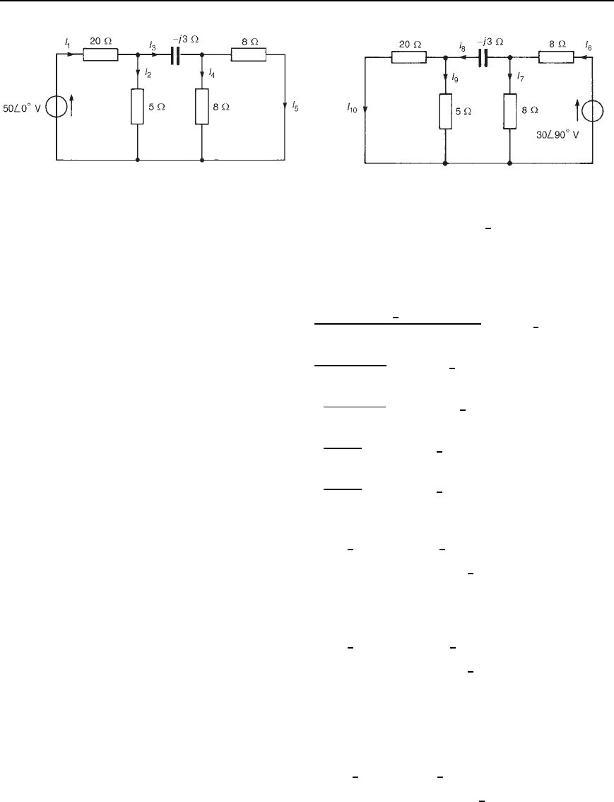
(i) The network is redrawn with the 30
6
90
°
V source removed, as
shown in Figure 32.26.
(ii) Currents I
1
to I
5
are shown labelled in Figure 32.26. From
Figure 32.26, two 8 resistors in parallel give an equivalent
resistance of 4 .
Hence I
1
D
50
6
0
°
20 C 54 j3/5 C 4 j3
D 2.220
6
2.12
°
A
I
2
D
4 j3
5 C 4 j3
I
1
D 1.170
6
16.32
°
A
I
3
D
5
5 C 4 j3
I
1
D 1.170
6
20.55
°
A
I
4
D
8
8 C 8
I
3
D 0.585
6
20.55
°
A D I
5
572 Electrical Circuit Theory and Technology
Figure 32.26 Figure 32.27
(iii) The original network is redrawn with the 50
6
0
°
V source removed,
as shown in Figure 32.27.
(iv) Currents I
6
to I
10
are shown labelled in Figure 32.27. From
Figure 32.27, 20 in parallel with 5 gives an equivalent
resistance of 20 ð5/20 C 5 D 4 .
Hence I
6
D
30
6
90
°
8 C 84 j3/8 C 4 j3
D 2.715
6
96.52
°
A
I
7
D
4 j3
8 C 4 j3
I
6
D 1.097
6
73.69
°
A
I
8
D
8
8 C 4 j3
I
6
D 1.756
6
110.56
°
A
I
9
D
20
20 C 5
I
8
D 1.405
6
110.56
°
A
and I
10
D
5
20 C 5
I
8
D 0.351
6
110.56
°
A
(a) The current flowing in the capacitor is given by
I
3
I
8
D 1.170
6
20.55
°
1.756
6
110.56
°
D 1.712 j1.233Aor2.11
6
35.76
°
A
i.e., the magnitude of the current in the capacitor is 2.11 A
(b) The p.d. across the 5 resistance is given by (I
2
C I
9
) (5).
I
2
C I
9
D 1.170
6
16.32
°
C 1.405
6
110.56
°
D 0.629 C j0.987Aor1.17
6
57.49
°
A
Hence the magnitude of the pd. across the 5 Z resistance is
1.175 D 5.85 V
(c) Active power dissipated in the 20 resistance is given by
I
1
I
10
2
20.
I
1
I
10
D 2.220
6
2.12
°
0.351
6
110.56
°
D 2.342 j0.247Aor2.355
6
6.02
°
A

The superposition theorem 573
Hence the active power dissipated in the 20 Z resistance is
2.355
2
20 D 111 W
(d) Active power developed by the 50
6
0
°
V source
P
1
D VI
1
I
10
cos
1
D 502.355 cos6.02
°
0
°
D 117.1W
Active power developed by 30
6
90 V source,
P
2
D 30I
6
I
5
cos
2
I
6
I
5
D 2.715
6
96.52
°
0.585
6
20.55
°
D 0.856 C j2.492Aor2.635
6
108.96
°
A
Hence P
2
D 302.635 cos108.96
°
90
°
D 74.8W.
Total power developed, P D P
1
C P
2
D 117.1 C 74.8 D 191.9W
(This value may be checked by summing the I
2
R powers dissipated
in the four resistors.)
Further problems on the superposition theorem may be found in
Section 32.3 following, problems 1 to 8.
32.3 Further problems
on the superposition
theorem
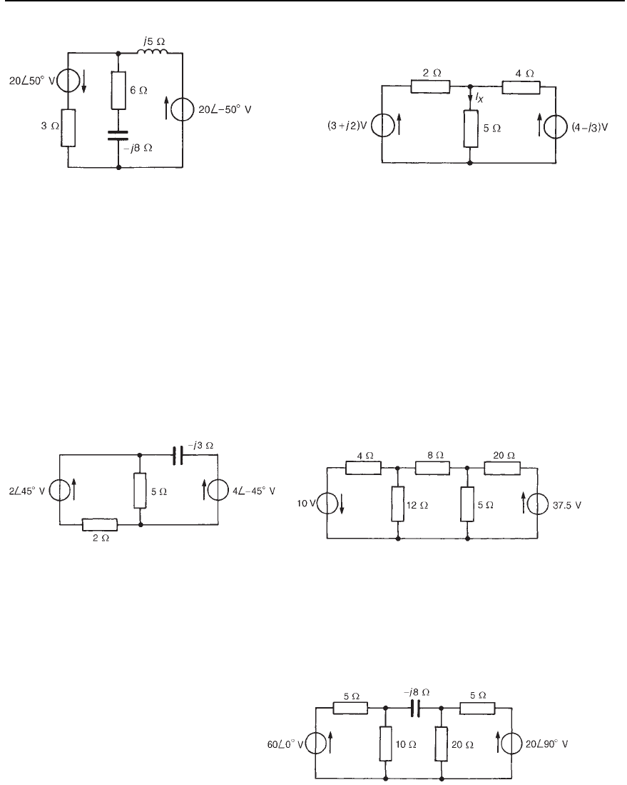
1 Repeat problems 1, 5, 8 and 9 on page 542, of Chapter 30, and prob-
lems 3, 5 and 13 on page 559, of Chapter 31, using the superposition
theorem.
2 Two batteries each of e.m.f. 15 V are connected in parallel to supply
a load of resistance 2.0 . The internal resistances of the batteries
are 0.5 and 0.3 . Determine, using the superposition theorem, the
current in the load and the current supplied by each battery.
[6.86 A; 2.57 A; 4.29 A]
3 Use the superposition theorem to determine the magnitude of the
current flowing in the capacitive branch of the network shown in
Figure 32.28. [2.584 A]
4 A.c. sources of 20
6
90
°
V and internal resistance 10 and 30
6
0
°
V
and internal resistance 12 are connected in parallel across an 8
load. Use the superposition theorem to determine (a) the current in
the 8 load, and (b) the current in each voltage source.
[(a) 1.30 A (b) 20
6
90
°
V source discharges at
1.58
6
120.98
°
A, 30
6
0
°
V source
discharges at 1.90
6
16.49
°
A]
5 Use the superposition theorem to determine current I
x
flowing in the
5 resistance of the network shown in Figure 32.29.
[0.529
6
5.71
°
A]
574 Electrical Circuit Theory and Technology
Figure 32.28 Figure 32.29
6 For the network shown in Figure 32.30, determine, using the superpo-
sition theorem, (a) the current flowing in the capacitor, (b) the current
flowing in the 2 resistance, (c) the p.d. across the 5 resistance,
and (d) the total active circuit power.
[(a) 1.28 A (b) 0.74 A (c) 3.01 V (d) 2.91 W]
7 (a) Use the superposition theorem to determine the current in the
12 resistance of the network shown in Figure 32.31. Deter-
mine also the p.d. across the 8 resistance and the power
dissipated in the 20 resistance.
(b) If the 37.5 V source in Figure 32.31 is reversed in direction,
determine the current in the 12 resistance.
[(a) 0.375 A, 8.0 V, 57.8 W (b) 0.625 A]
Figure 32.30 Figure 32.31
8 For the network shown in Figure 32.32, use the superposition theorem
to determine (a) the current in the capacitor, (b) the pd. across the
10 resistance, (c) the active power dissipated in the 20 resistance,
and (d) the total active circuit power.
[(a) 3.97 A (b) 28.7 V (c) 36.4 W (d) 371.6 W]
Figure 32.32

33 Th
´
evenin’s and
Norton’s theorems
At the end of this chapter you should be able to:
ž understand and use Th
´
evenin’s theorem to analyse a.c. and
d.c. networks
ž understand and use Norton’s theorem to analyse a.c. and d.c.
networks
ž appreciate and use the equivalence of Th
´
evenin and Norton
networks
33.1 Introduction
Many of the networks analysed in Chapters 30, 31 and 32 using
Kirchhoff’s laws, mesh-current and nodal analysis and the superposition
theorem can be analysed more quickly and easily by using Th
´
evenin’s
or Norton’s theorems. Each of these theorems involves replacing what
may be a complicated network of sources and linear impedances with a
simple equivalent circuit. A set procedure may be followed when using
each theorem, the procedures themselves requiring a knowledge of basic
circuit theory. (It may be worth checking some general d.c. circuit theory
in Section 13.4. page 174, before proceeding)
33.2 Th
´
evenin’s theorem
Th
´
evenin’s theorem states:
‘The current which flows in any branch of a network is the same as that
which would flow in the branch if it were connected across a source of
electrical energy, the e.m.f. of which is equal to the potential difference
which would appear across the branch if it were open-circuited, and the
internal impedance of which is equal to the impedance which appears
across the open-circuited branch terminals when all sources are replaced
by their internal impedances.’
The theorem applies to any linear active network (‘linear’ meaning that the
measured values of circuit components are independent of the direction
and magnitude of the current flowing in them, and ‘active’ meaning that
it contains a source, or sources, of e.m.f.)
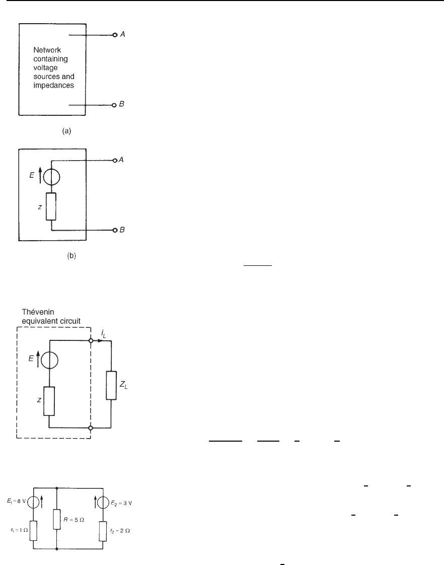
The above statement of Th
´
evenin’s theorem simply means that
a complicated network with output terminals AB, as shown in
Figure 33.1(a), can be replaced by a single voltage source E in series
with an impedance z, as shown in Figure 33.1(b). E is the open-circuit
576 Electrical Circuit Theory and Technology
Figure 33.1 The Th´evenin
equivalent circuit
voltage measured at terminals AB and z is the equivalent impedance of
the network at the terminals AB when all internal sources of e.m.f. are
made zero. The polarity of voltage E is chosen so that the current flowing
through an impedance connected between A and B will have the same
direction as would result if the impedance had been connected between A
and B of the original network. Figure 33.1(b) is known as the Th
´
evenin
equivalent circuit, and was initially introduced in Section 13.4, page 174
for d.c. networks.
The following four-step procedure can be adopted when determining,
by means of Th
´
evenin’s theorem, the current flowing in a branch
containing impedance Z
L
of an active network:
(i) remove the impedance Z
L
from that branch;
(ii) determine the open-circuit voltage E across the break;
(iii) remove each source of e.m.f. and replace it by its internal impedance
(if it has zero internal impedance then replace it by a short-
circuit), and then determine the internal impedance, z, ‘looking in’
at the break;
(iv) determine the current from the Th
´
evenin equivalent circuit shown
in Figure 33.2, i.e.
current i
L
=
E
Z
L
Y z
.
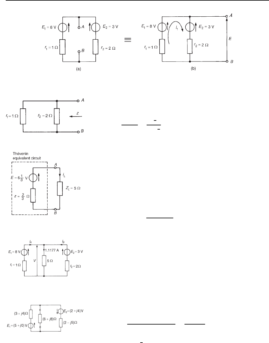
A simple d.c. network (Figure 33.3) serves to demonstrate how the above
procedure is applied to determine the current flowing in the 5 resis-
tance by using Th
´
evenin’s theorem. This is the same network as used in
Chapter 30 when it was solved using Kirchhoff’s laws (see page 535),
and by means of the superposition theorem in Chapter 32 (see page 562).
A comparison of methods may be made.
Using the above procedure:
(i) the 5 resistor is removed, as shown in Figure 33.4(a).
(ii) The open-circuit voltage E across the break is now required. The
network of Figure 33.4(a) is redrawn for convenience as shown in
Figure 33.4(b), where current,
I
1
D
E
1
E
2
r
1
C r
2
D
8 3
1 C 2
D
5
3
or 1
2
3
A
Figure 33.2
Hence the open-circuit voltage E is given by
E D E
1
I
1
r
1
i.e., E D 8
1
2
3
1 D 6
1
3
V
(Alternatively, E D E
2
I
1
r
2
D 3 C
1
2
3
2 D 6
1
3
V.
(iii) Removing each source of e.m.f. gives the network of Figure 33.5.
The impedance, z, ‘looking in’ at the break AB is given by
z D 1 ð2/1 C 2 D
2
3
Figure 33.3
Th´evenin’s and Norton’s theorems 577
Figure 33.4
(iv) The Th
´
evenin equivalent circuit is shown in Figure 33.6, where
current i
L
is given by
i
L
D
E
Z
L
C z
D
6
1
3
5 C
2
3
D 1.1177
D 1.12 A, correct to two decimal places
Figure 33.5
To determine the currents flowing in the other two branches of
the circuit of Figure 33.3, basic circuit theory is used. Thus, from
Figure 33.7, voltage V D 1.11775 D 5.5885 V.
Then V D E
1
I
A
r
1
, i.e., 5.5885 D 8 I
A
1, from which
current I
A
D 8 5.5885 D 2.41 A.
Similarly, V D E
2
I
B
r
2
, i.e., 5.5885 D 3 I
B
2, from which
current I
B
D
3 5.5885
2
D
−1.29 A
Figure 33.6
(i.e., flowing in the direction opposite to that shown in Figure 33.7).
The Th
´
evenin theorem procedure used above may be applied to a.c. as
well as d.c. networks, as shown below.
An a.c. network is shown in Figure 33.8 where it is required to find the
current flowing in the 6 C j8 impedance by using Th
´
evenin’s theorem.
Figure 33.7
Using the above procedure
(i) The 6 C j8 impedance is removed, as shown in Figure 33.9(a).
(ii) The open-circuit voltage across the break is now required. The
network is redrawn for convenience as shown in Figure 33.9(b),
where current
I
1
D
5 C j0 C 2 C j4
3 C j4 C 2 j5
D
7 C j4
5 j
D 1.581
6
41.05
°
A
Figure 33.8
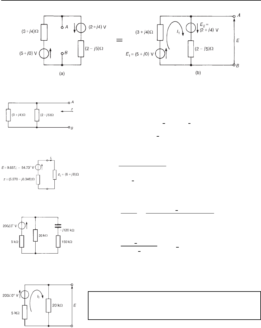
578 Electrical Circuit Theory and Technology
Figure 33.9
Hence open-circuit voltage across AB,
E D E
1
I
1
3 C j4, i.e.,
E D 5 C j0 1.581
6
41.05
°
5
6
53.13
°
from which E D 9.567
6
54.73
°
V
Figure 33.10
(iii) From Figure 33.10, the impedance z ‘looking in’ at terminals AB
is given by
z D
3 C j42 j5
3 C j4 C 2 j5
D 5.281
6
3.76
°
or 5.270 j0.346
(iv) The Th
´
evenin equivalent circuit is shown in Figure 33.11, from
which current
i
L
D
E
Z
L
C z
D
9.657
6
54.73
°
6 C j8 C 5.270 j0.346
Figure 33.11
Thus, current in 6 C j8 impedance,
i
L
D
9.657
6
54.73
°
13.623
6
34.18
°
D 0.71
66
−88.91
°
A
The network of Figure 33.8 is analysed using Kirchhoff’s laws in
problem 3, page 539, and by the superposition theorem in problem 4,
page 568. The above analysis using Th
´
evenin’s theorem is seen to be
much quicker.
Figure 33.12
Problem 1. For the circuit shown in Figure 33.12, use Th
´
evenin’s
theorem to determine (a) the current flowing in the capacitor, and
(b) the p.d. across the 150 k resistor.
(a) (i) Initially the 150 j120k impedance is removed from the
circuit as shown in Figure 33.13.
Figure 33.13
