Bird J. Electrical Circuit Theory and Technology
Подождите немного. Документ загружается.

548 Electrical Circuit Theory and Technology
Thus, using determinants,
I
1
j4 100
4 j 0
D
I
2
5 j4 100
j40
D
1
5 j4j4
j4 4 j
I
1
400 j100
D
I
2
j400
D
1
32 j21
Hence I
1
D
400 j100
32 j21
D
412.31
6
14.04
°
38.28
6
33.27
°
D 10.77
6
19.23
°
A D 10.8
66
−19.2
°
A,
correct to one decimal place
I
2
D
400
6
90
°
38.28
6
33.27
°
D 10.45
6
56.73
°
A
D 10.5
66
−56.7
°
A,
correct to one decimal place
(b) Current flowing in capacitor D I
1
I
2
D 10.77
6
19.23
°
10.45
6
56.73
°
D 4.44 C j12.28 D 13.1
6
70.12
°
A,
i.e., the current in the capacitor is 13.1 A
(c) Source power P D VIcos D 10010.77 cos19.23
°
D 1016.9WD 1020 W,
correct to three significant figures.
(Check: power in 5 resistor D I
2
1
5 D 10.77
2
5 D 579.97 W
and power in 4 resistor D I
2
2
4 D 10.45
2
4 D 436.81 W
Thus total power dissipated D 579.97 C 436.81
D 1016.8WD 1020 W, correct
to three significant figures.)
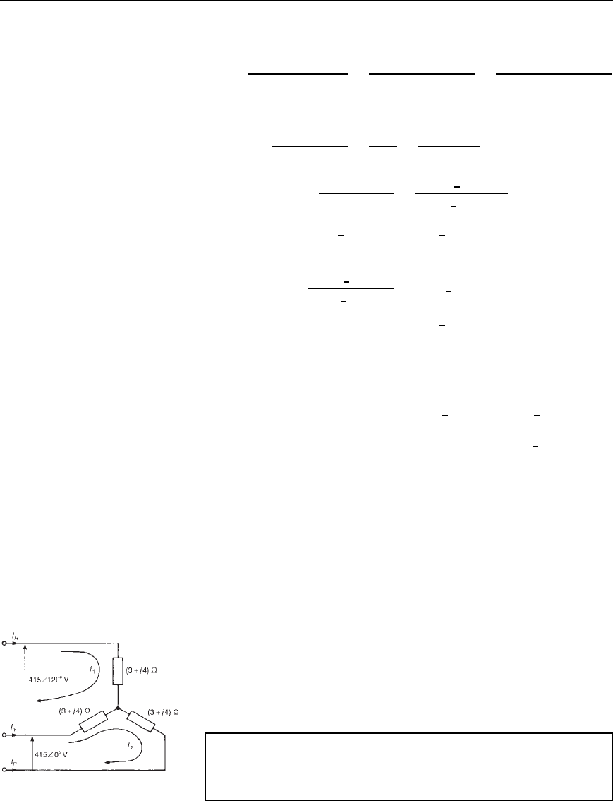
Problem 3. A balanced star-connected 3-phase load is shown in
Figure 31.4. Determine the value of the line currents I
R
,I
Y
and I
B
using mesh-current analysis.
Figure 31.4
Mesh-current and nodal analysis 549
Two mesh currents I
1
and I
2
are chosen as shown in Figure 31.4.
From loop 1, I
1
3 C j4 C I
1
3 C j4 I
2
3 C j4 D 415
6
120
°
i.e., 6 C j8I
1
3 Cj4I
2
415
6
120
°
D 0 1
From loop 2, I
2
3 C j4 I
1
3 C j4 C I
2
3 C j4 D 415
6
0
°
i.e., 3 C j4I
1
C 6 Cj8I
2
415
6
0
°
D 0 2
Solving equations (1) and (2) using determinants gives:
I
1
3 C j4 415
6
120
°
6 C j8 415
6
0
°
D
I
2
6 C j8 415
6
120
°
3 C j4 415
6
0
°
D
1
6 C j8 3 Cj4
3 C j46 C j8
I
1
2075
6
53.13
°
C 4150
6
173.13
°
D
I
2
4150
6
53.13
°
2075
6
173.13
°
D
1
100
6
106.26
°
25
6
106.26
°
I
1
3594
6
143.13
°
D
I
2
3594
6
83.13
°
D
1
75
6
106.26
°
Hence I
1
D
3594
6
143.13
°
75
6
106.26
°
D 47.9
6
36.87
°
A
and I
2
D
3594
6
83.13
°
75
6
106.26
°
D 47.9
6
23.13
°
A
Thus line current I
R
D I
1
D 47.9
66
36.87
°
A
I
B
DI
2
D47.9
6
23.23
°
A
D 47.9
66
156.87
°
A
and I
Y
D I
2
I
1
D 47.9
6
23.13
°
47.9
6
36.87
°
D 47.9
66
−83.13
°
A
Further problems on mesh-current analysis may be found in Section 31.3,
problems 1 to 9, page 559.
550 Electrical Circuit Theory and Technology
31.2 Nodal analysis
A node of a network is defined as a point where two or more branches
are joined. If three or more branches join at a node, then that node is
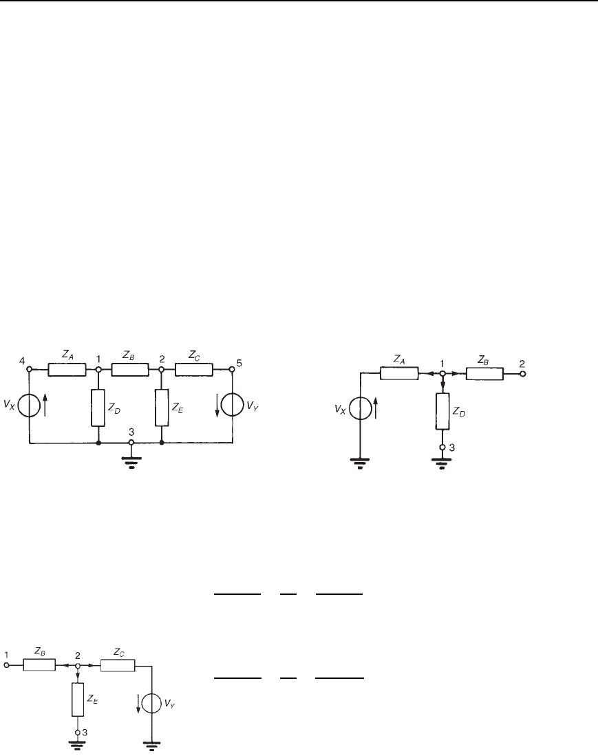
called a principal node or junction. In Figure 31.5, points 1, 2, 3, 4 and
5 are nodes, and points 1, 2 and 3 are principal nodes.
A node voltage is the voltage of a particular node with respect to a
node called the reference node. If in Figure 31.5, for example, node 3 is
chosen as the reference node then V
13
is assumed to mean the voltage
at node 1 with respect to node 3 (as distinct from V
31
). Similarly, V
23
would be assumed to mean the voltage at node 2 with respect to node 3,
and so on. However, since the node voltage is always determined with
respect to a particular chosen reference node, the notation V
1
for V
13
and
V
2
for V
23
would always be used in this instance.
The object of nodal analysis is to determine the values of voltages at
all the principal nodes with respect to the reference node, e.g., to find
voltages V
1
and V
2
in Figure 31.5. When such voltages are determined,
the currents flowing in each branch can be found.
Kirchhoff’s current law is applied to nodes 1 and 2 in turn in
Figure 31.5 and two equations in unknowns V
1
and V
2
are obtained which
may be simultaneously solved using determinants.
Figure 31.5 Figure 31.6
The branches leading to node 1 are shown separately in Figure 31.6.
Let us assume that all branch currents are leaving the node as shown.
Since the sum of currents at a junction is zero,
V
1
V
x
Z
A
C
V
1
Z
D
C
V
1
V
2
Z
B
D 0 1
Similarly, for node 2, assuming all branch currents are leaving the node
as shown in Figure 31.7,
V
2
V
1
Z
B
C
V
2
Z
E
C
V
2
C V
Y
Z
C
D 0 2
In equations (1) and (2), the currents are all assumed to be leaving the
node. In fact, any selection in the direction of the branch currents may
be made—the resulting equations will be identical. (For example, if for
node 1 the current flowing in Z
B
is considered as flowing towards node 1
instead of away, then the equation for node 1 becomes
Figure 31.7
Mesh-current and nodal analysis 551
V
1
V
x
Z
A
C
V
1
Z
D
D
V
2
V
1
Z
B
which if rearranged is seen to be exactly the same as equation (1).)
Rearranging equations (1) and (2) gives:
1
Z
A
C
1
Z
B
C
1
Z
D
V
1
1
Z
B
V
2
1
Z
A
V
x
D 0 3
1
Z
B
V
1
C
1
Z
B
C
1
Z
C
C
1
Z
E
V
2
C
1
Z
C
V
Y
D 0 4
Equations (3) and (4) may be rewritten in terms of admittances (where
admittance Y D l/Z ):
Y
A
C Y
B
C Y
D
V
1
Y
B
V
2
Y
A
V
x
D 0 5
Y
B
V
1
C Y
B
C Y
C
C Y
E
V
2
C Y
C
V
Y
D 0 6
Equations (5) and (6) may be solved for V
1
and V
2
by using determinants.
Thus
V
1
Y
B
Y
A
Y
B
C Y
C
C Y
E
Y
C
D
V
2
Y
A
C Y
B
C Y
D
Y
A
Y
B
Y
C
D
1
Y
A
C Y
B
C Y
D
Y
B
Y
B
Y
B
C Y
C
C Y
E
Current equations, and hence voltage equations, may be written at each
principal node of a network with the exception of a reference node. The
number of equations necessary to produce a solution for a circuit is, in
fact, always one less than the number of principal nodes.
Whether mesh-current analysis or nodal analysis is used to determine
currents in circuits depends on the number of loops and nodes the circuit
contains, Basically, the method that requires the least number of equations
is used. The method of nodal analysis is demonstrated in the following
problems.
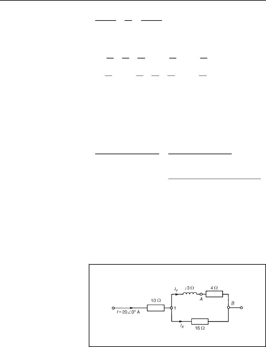
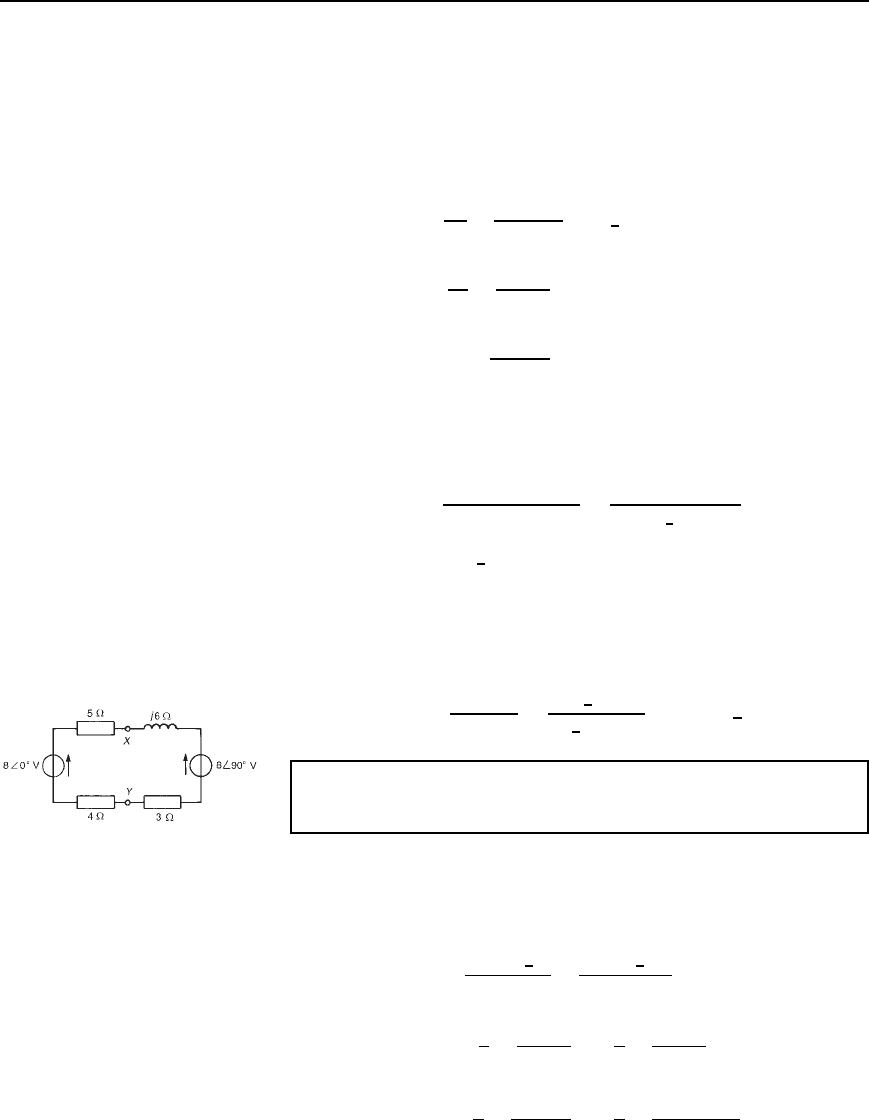
Problem 4. For the network shown in Figure 31.8, determine the
voltage V
AB
, by using nodal analysis.
Figure 31.8
552 Electrical Circuit Theory and Technology
Figure 31.8 contains two principal nodes (at 1 and B) and thus only one
nodal equation is required. B is taken as the reference node and the equa-
tion for node 1 is obtained as follows. Applying Kirchhoff’s current law
to node 1 gives:
I
X
C I
Y
D I
i.e.,
V
1
16
C
V
1
4 C j3
D 20
6
0
°
Thus V
1
1
16
C
1
4 C j3
D 20
V
1
0.0625 C
4 j3
4
2
C 3
2
D 20
V
1
0.0625 C 0.16 j0.12 D 20
V
1
0.2225 j0.12 D 20
from which, V
1
D
20
0.2225 j0.12
D
20
0.2528
6
28.34
°
i.e., voltage V
1
D 79.1
6
28.34
°
V
The current through the 4 C j3 branch, I
y
D V
1
/4 C j3
Hence the voltage drop between points A and B, i.e., across the 4
resistance, is given by:
V
AB
D I
y
4 D
V
1
4
4 C j3
D
79.1
6
28.34
°
5
6
36.87
°
4 D 63.3
66
−8.53
°
V
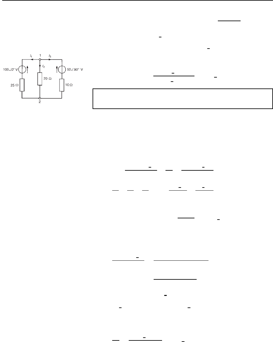
Problem 5. Determine the value of voltage V
XY
shown in the
circuit of Figure 31.9.
Figure 31.9
The circuit contains no principal nodes. However, if point Y is chosen as
the reference node then an equation may be written for node X assuming
that current leaves point X by both branches.
Thus
V
X
8
6
0
°
5 C 4
C
V
x
8
6
90
°
3 C j6
D 0
from which, V
X
1
9
C
1
3 C j6
D
8
9
C
j8
3 C j6
V
X
1
9
C
3 j6
3
2
C 6
2
D
8
9
C
j83 j6
3
2
C 6
2
Mesh-current and nodal analysis 553
V
X
0.1778 j0.1333 D 0.8889 C
48 C j24
45
V
X
0.2222
6
36.86
°
D 1.9556 C j0.5333
D 2.027
6
15.25
°
Since point Y is the reference node,
voltage V
X
D V
XY
D
2.027
6
15.25
°
0.2222
6
36.86
°
D 9.12
66
52.11
°
V
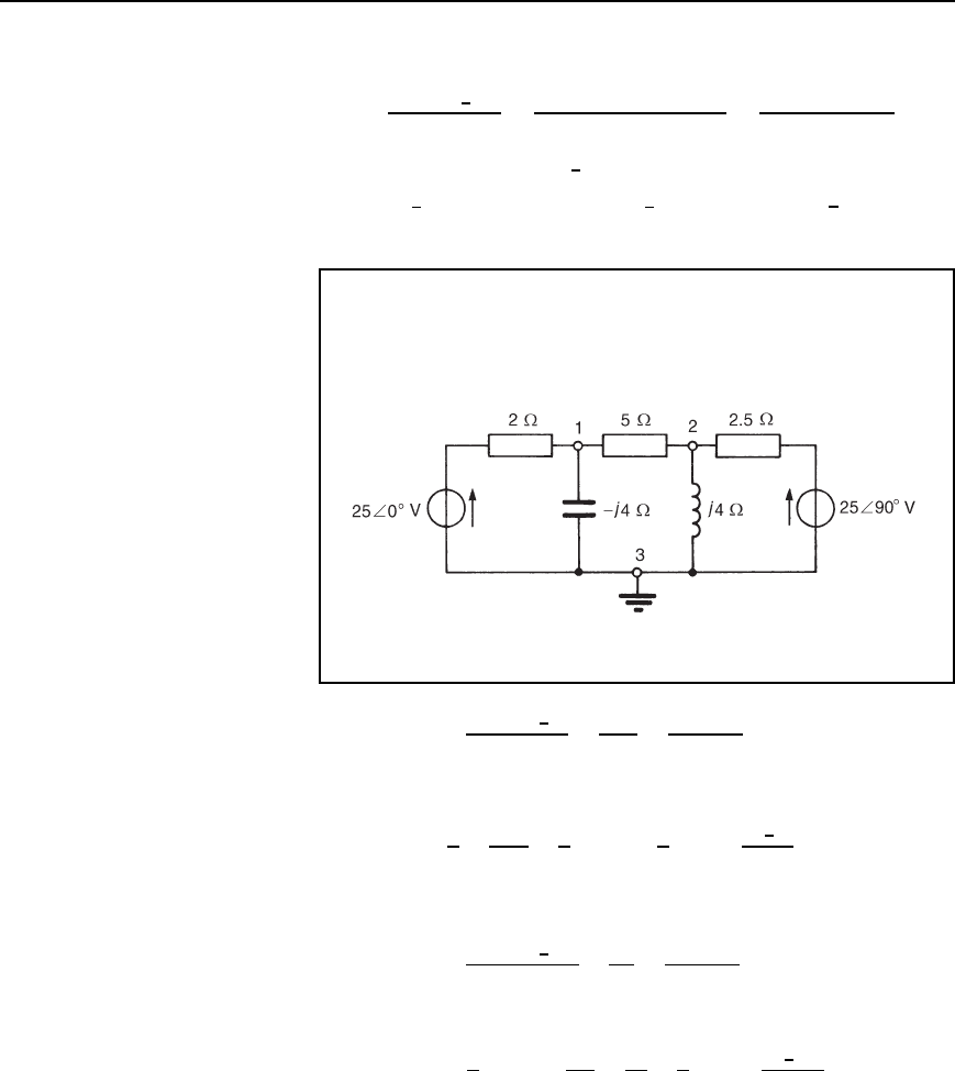
Problem 6. Use nodal analysis to determine the current flowing
in each branch of the network shown in Figure 31.10.
Figure 31.10
This is the same problem as problem 1 of Chapter 30, page 536, which
was solved using Kirchhoff’s laws. A comparison of methods can
be made.
There are only two principal nodes in Figure 31.10 so only one nodal
equation is required. Node 2 is taken as the reference node.
The equation at node 1 is I
1
C I
2
C I
3
D 0
i.e.,
V
1
100
6
0
°
25
C
V
1
20
C
V
1
50
6
90
°
10
D 0
i.e.,
1
25
C
1
20
C
1
10
V
1
100
6
0
°
25
50
6
90
°
10
D 0
0.19 V
1
D 4 C j5
Thus the voltage at node 1,V
1
D
4 C j5
0.19
D 33.70
6
51.34
°
V
or 21.05 C j26.32V
Hence the current in the 25 resistance,
I
1
D
V
1
100
6
0
°
25
D
21.05 C j26.32 100
25
D
78.95 C j26.32
25
D 3.33
66
161.56
°
A flowing away from node 1
or 3.33
6
161.56
°
180
°
A D 3.33
66
−18.44
°
A flowing toward
node 1)
The current in the 20 resistance,
I
2
D
V
1
20
D
33.70
6
51.34
°
20
D 1.69
66
51.34
°
A
flowing from node 1 to node 2
554 Electrical Circuit Theory and Technology
The current in the 10 resistor,
I
3
D
V
1
50
6
90
°
10
D
21.05 C j26.32 j50
10
D
21.05 j23.68
10
D 3.17
66
−48.36
°
A away from node 1
or 3.17
6
48.36
°
180
°
D 3.17
6
228.36
°
A D 3.17
66
131.64
°
A
toward node 1)
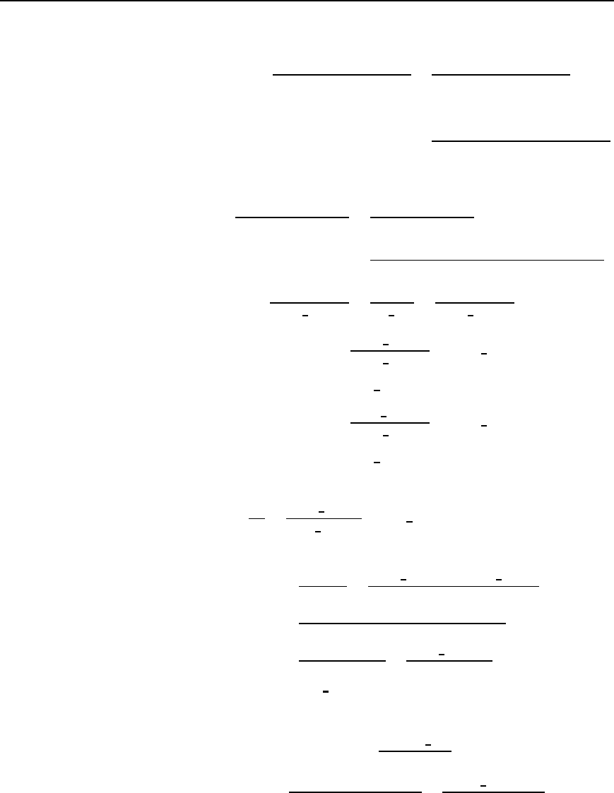
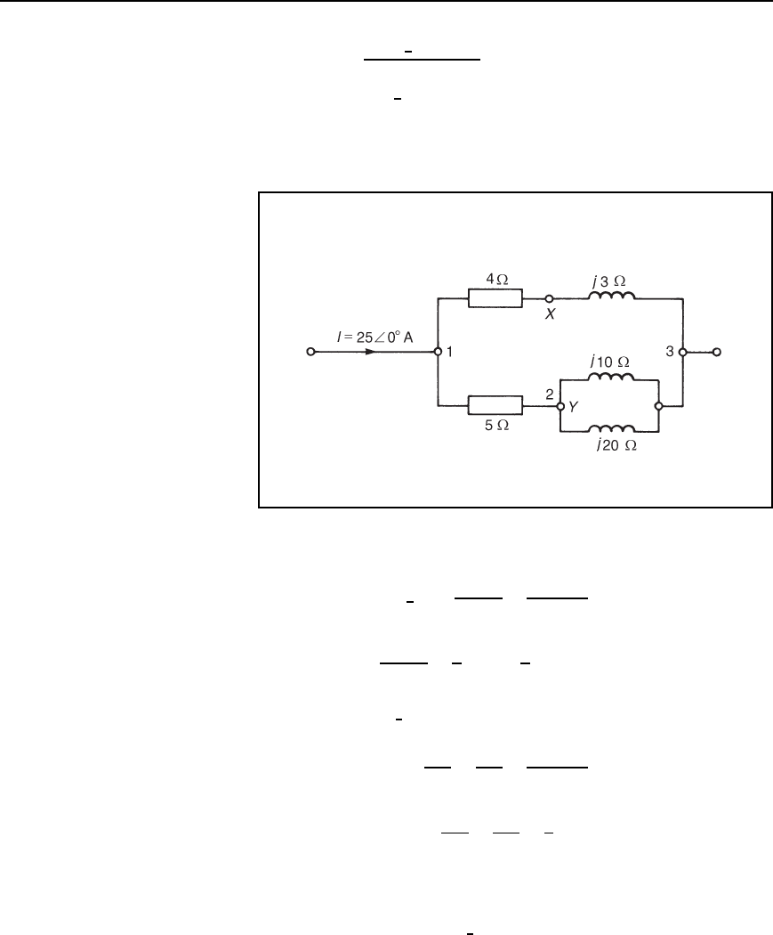
Problem 7. In the network of Figure 31.11 use nodal analysis to
determine (a) the voltage at nodes 1 and 2, (b) the current in the
j4 inductance, (c) the current in the 5 resistance, and (d) the
magnitude of the active power dissipated in the 2.5 resistance.
Figure 31.11
(a) At node 1,
V
1
25
6
0
°
2
C
V
1
j4
C
V
1
V
2
5
D 0
Rearranging gives:
1
2
C
1
j4
C
1
5
V
1
1
5
V
2
25
6
0
°
2
D 0
i.e., 0.7 C j0.25V
1
0.2V
2
12.5 D 0 1
At node 2,
V
2
25
6
90
°
2.5
C
V
2
j4
C
V
2
V
1
5
D 0
Rearranging gives:
1
5
V
1
C
1
2.5
C
1
j4
C
1
5
V
2
25
6
90
°
2.5
D 0
i.e., 0.2V
1
C 0.6 j0.25V
2
j10 D 0 2
Thus two simultaneous equations have been formed with two
unknowns, V
1
and V
2
. Using determinants, if
0.7 C j0.25V
1
0.2V
2
12.5 D 0 1
Mesh-current and nodal analysis 555
and 0.2V
1
C 0.6 j0.25V
2
j10 D 0 2
then
V
1
0.2 12.5
0.6 j0.25 j10
D
V
2
0.7 C j0.25 12.5
0.2 j10
D
1
0.7 C j0.25 0.2
0.2 0.6 j0.25
i.e.,
V
1
j2 C 7.5 j3.125
D
V
2
j7 C 2.5 2.5
D
1
0.42 j0.175 C j0.15 C 0.0625 0.04
and
V
1
7.584
6
8.53
°
D
V
2
7
6
90
°
D
1
0.443
6
3.23
°
Thus voltage, V
1
D
7.584
6
8.53
°
0.443
6
3.23
°
D 17.12
6
5.30
°
V
D 17.1
66
−5.3
°
V, correct to one decimal place,
and voltage, V
2
D
7
6
90
°
0.443
6
3.23
°
D 15.80
6
93.23
°
V
D 15.8
66
93.2
°
V, correct to one decimal place.
(b) The current in the j4 inductance is given by:
V
2
j4
D
15.80
6
93.23
°
4
6
90
°
D 3.95
66
3.23
°
A flowing away from node 2
(c) The current in the 5 resistance is given by:
I
5
D
V
1
V
2
5
D
17.12
6
5.30
°
15.80
6
93.23
°
5
i.e., I
5
D
17.05 j1.58 0.89 C j15.77
5
D
17.94 j17.35
5
D
24.96
6
44.04
°
5
D 4.99
66
−44.04
°
A flowing from node 1 to node 2
(d) The active power dissipated in the 2.5 resistor is given by
P
2.5
D I
2.5
2
2.5 D
V
2
25
6
90
°
2.5
2
2.5
D
0.89 C j15.77 j25
2
2.5
D
9.273
6
95.51
°
2
2.5
556 Electrical Circuit Theory and Technology
D
85.99
6
191.02
°
2.5
by de Moivre’s theorem
D 34.4
6
169
°
W
Thus the magnitude of the active power dissipated in the 2.5 Z
resistance is 34.4 W
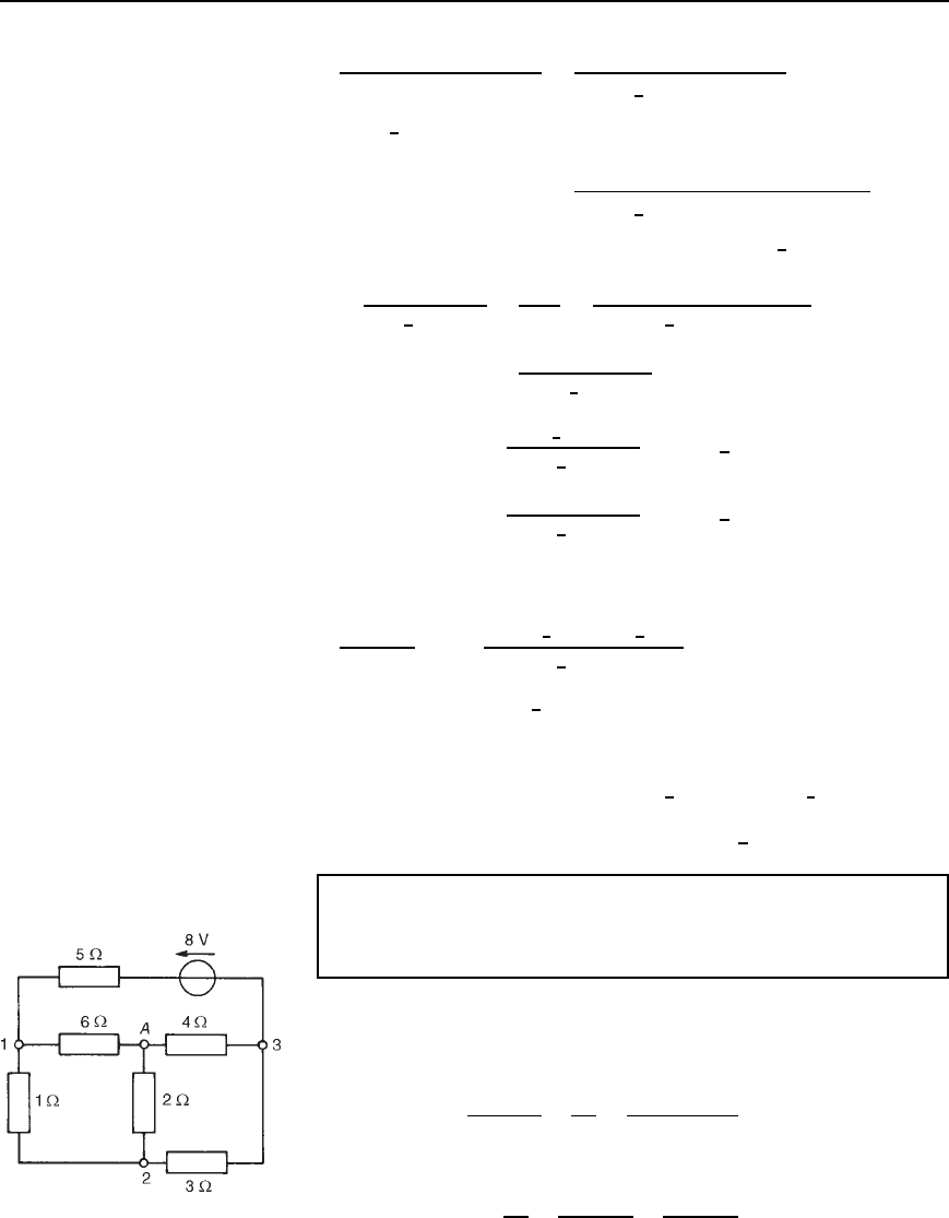
Problem 8. In the network shown in Figure 31.12 determine the
voltage V
XY
using nodal analysis.
Figure 31.12
Node 3 is taken as the reference node.
At node 1, 25
6
0
°
D
V
1
4 C j3
C
V
1
V
2
5
i.e.,
4 j3
25
C
1
5
V
1
1
5
V
2
25 D 0
or 0.379
6
18.43
°
V
1
0.2V
2
25 D 0 1
At node 2,
V
2
j10
C
V
2
j20
C
V
2
V
1
5
D 0
i.e., 0.2V
1
C
1
j10
C
1
j20
C
1
5
V
2
D 0
or 0.2V
1
C j0.1 j0.05 C 0.2V
2
D 0
i.e., 0.2V
1
C 0.25
6
36.87
°
V
2
C 0 D 0 2
Simultaneous equations (1) and (2) may be solved for V
1
and V
2
by using
determinants. Thus,
Mesh-current and nodal analysis 557
V
1
0.2 25
0.25
6
36.87
°
0
D
V
2
0.379
6
18.43
°
25
0.20
D
1
0.379
6
18.43
°
0.2
0.20.25
6
36.87
°
i.e.,
V
1
6.25
6
36.87
°
D
V
2
5
D
1
0.09475
6
55.30
°
0.04
D
1
0.079
6
79.85
°
Hence voltage, V
1
D
6.25
6
36.87
°
0.079
6
79.85
°
D 79.11
66
42.98
°
V
and voltage, V
2
D
5
0.079
6
79.85
°
D 63.29
66
79.85
°
V
The current flowing in the 4 Cj3 branch is V
1
/4 C j3. Hence the
voltage between point X and node 3 is:
V
1
4 C j3
j3 D
79.11
6
42.98
°
3
6
90
°
5
6
36.87
°
D 47.47
6
96.11
°
V
Thus the voltage
V
XY
D V
X
V
Y
D V
X
V
2
D 47.47
6
96.11
°
63.29
6
79.85
°
D16.21 j15.10 D 22.15
66
−137
°
V
Problem 9. Use nodal analysis to determine the voltages at nodes
2 and 3 in Figure 31.13 and hence determine the current flowing
in the 2 resistor and the power dissipated in the 3 resistor.
This is the same problem as Problem 2 of Chapter 30, page 537, which
was solved using Kirchhoff’s laws.
In Figure 31.13, the reference node is shown at point A.
At node 1,
V
1
V
2
1
C
V
1
6
C
V
1
8 V
3
5
D 0
i.e., 1.367V
1
V
2
0.2V
3
1.6 D 0 1
At node 2,
V
2
2
C
V
2
V
1
1
C
V
2
V
3
3
D 0
Figure 31.13
