Bird J. Electrical Circuit Theory and Technology
Подождите немного. Документ загружается.

518 Electrical Circuit Theory and Technology
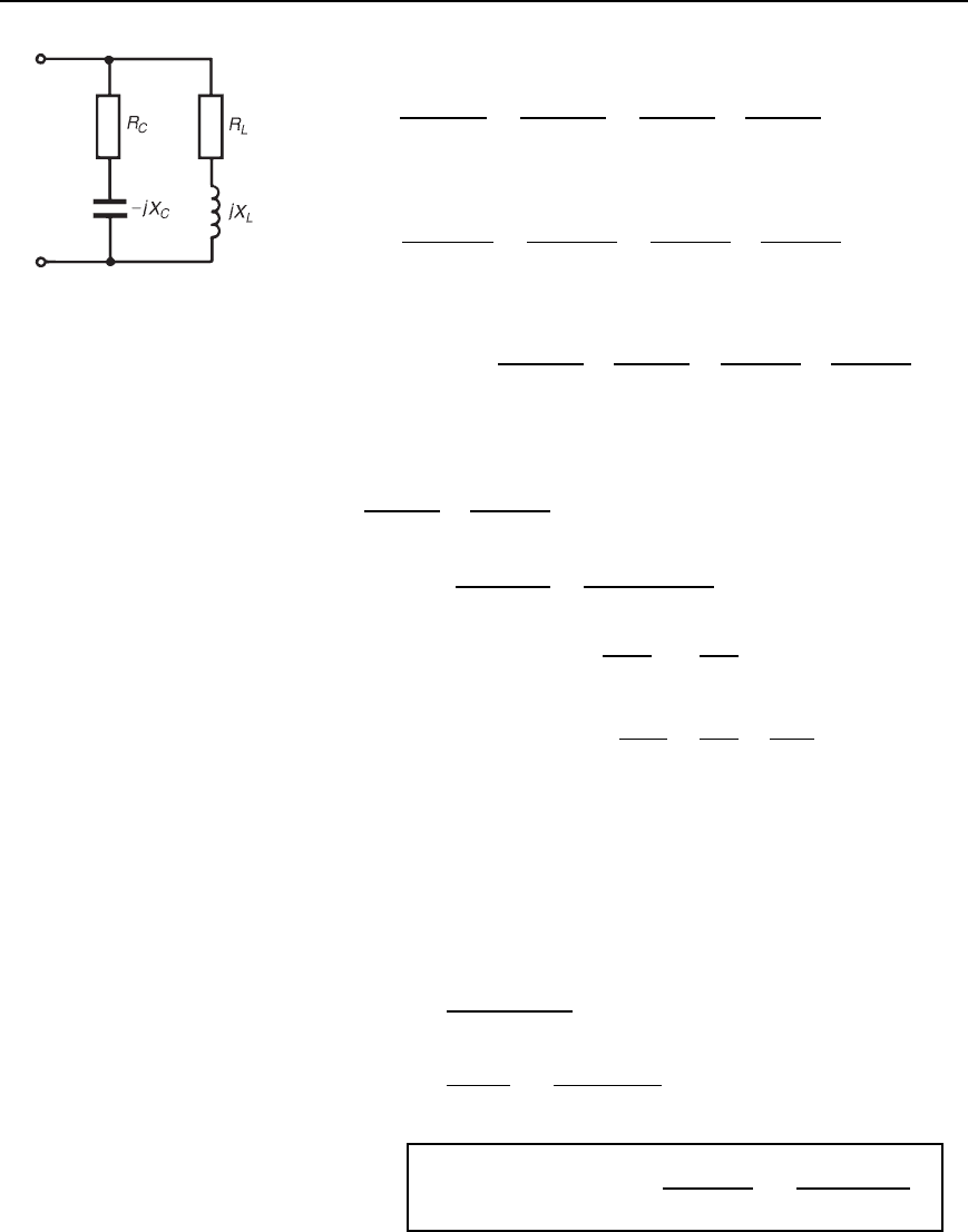
Figure 29.4
Admittance of inductive branch,
Y
L
D
1
R
L
C jX
L
D
R
L
jX
L
R
2
L
C X
2
L
D
R
L
R
2
L
C X
2
L
jX
L
R
2
L
C X
2
L
Admittance of capacitive branch,
Y
C
D
1
R
C
jX
C
D
R
C
C jX
C
R
2
C
C X
2
C
D
R
C
R
2
C
C X
2
C
C
jX
C
R
2
C
C X
2
C
Total network admittance,
Y D Y
L
C Y
C
D
R
L
R
2
L
C jX
2
L
jX
L
R
2
L
C X
2
L
C
R
C
R
2
C
C X
2
C
C
jX
C
R
2
C
C X
2
C
At resonance the admittance is a minimum, i.e., when the imaginary part
of Y is zero. Hence, at resonance,
X
L
R
2
L
C X
2
L
C
X
C
R
2
C
C X
2
C
D 0
i.e.,
ω
r
L
R
2
L
C ω
2
L
2
D
1/ω
r
C
R
2
C
C 1/ω
2
r
C
2
29.5
Rearranging gives: ω
r
L
R
2
C
C
1
ω
2
r
C
2
D
1
ω
r
C
R
2
L
C ω
2
r
L
2
ω
r
LR
2
C
C
L
ω
r
C
2
D
R
2
L
ω
r
C
C
ω
r
L
2
C
Multiplying throughout by ω
r
C
2
gives:
ω
2
r
C
2
LR
2
C
C L D R
2
L
C C ω
2
r
L
2
C
ω
2
r
C
2
LR
2
C
L
2
C D R
2
L
C L
ω
2
r
CLCR
2
C
L D R
2
L
C L
Hence ω
2
r
D
CR
2
L
L
LCCR
2
C
L
i.e., ω
r
D
1
p
LC
R
2
L
L/C
R
2
C
L/C
Hence
resonant frequency, f
r
=
1
2p
p
.LC/
R
2
L
− .L=C/
R
2
C
− .L=C/
29.6
Parallel resonance and Q-factor 519
It is clear from equation (29.5) that parallel resonance may be achieved
in such a circuit in several ways — by varying either the frequency f,
the inductance L, the capacitance C, the resistance R
L
or the resis-
tance R
C
.
29.5 Q-factor in a
parallel network
The Q-factor in the series R–L –C circuit is a measure of the voltage
magnification. In a parallel circuit, currents higher than the supply current
can circulate within the parallel branches of a parallel resonant network,
the current leaving the capacitor and establishing the magnetic field of
the inductance, this then collapsing and recharging the capacitor, and
so on. The Q-factor of a parallel resonant circuit is the ratio of the
current circulating in the parallel branches of the circuit to the supply
current, i.e. in a parallel circuit, Q-factor is a measure of the current
magnification.
Circulating currents may be several hundreds of times greater than the
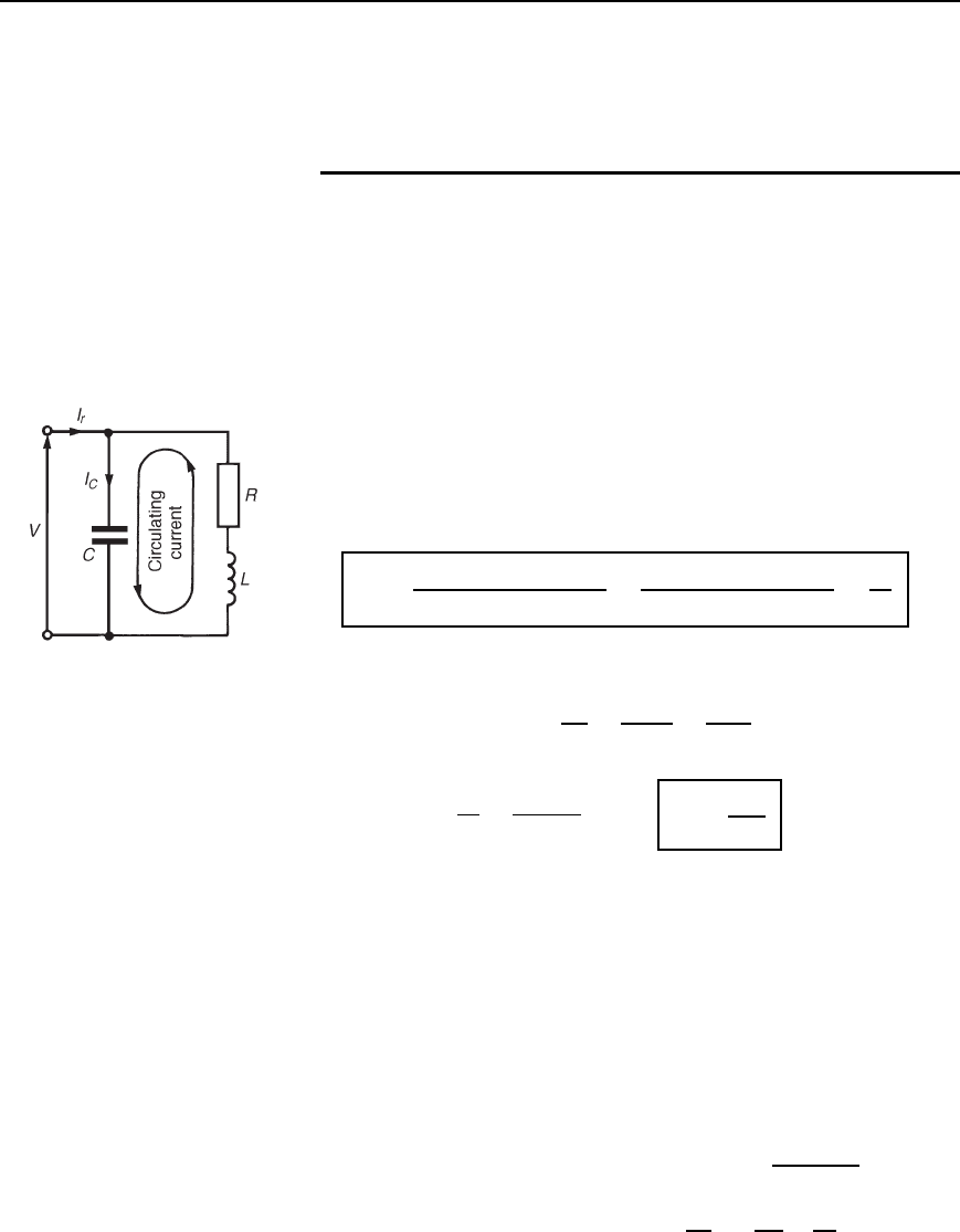
supply current at resonance. For the parallel network of Figure 29.5, the
Q-factor at resonance is given by:
Q
r
=
circulating current
current at resonance
=
capacitor current
current at resonance
=
I
C
I
r
Current in capacitor, I
C
D V/X
C
D Vω
r
C
Figure 29.5
Current at resonance, I
r
D
V
R
D
D
V
L/CR
D
VCR
L
Hence Q
r
D
I
C
I
r
D
Vω
r
C
VCR/L
i.e.,
Q
r
=
!
r
L
R
the same expression as for series resonance.
The difference between the resonant frequency of a series circuit and
that of a parallel circuit can be quite small. The resonant frequency of
a coil in parallel with a capacitor is shown in Equation (29.3); however,
around the closed loop comprising the coil and capacitor the energy would
naturally resonate at a frequency given by that for a series R–L –C circuit,
as shown in Chapter 28. This latter frequency is termed the natural
frequency, f
n
, and the frequency of resonance seen at the terminals of
Figure 29.5 is often called the forced resonant frequency, f
r
. (For a
series circuit, the forced and natural frequencies coincide.)
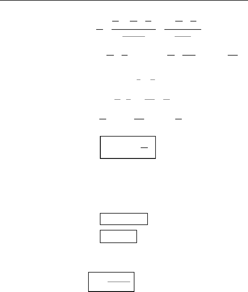
From the coil-capacitor loop of Figure 29.5, f
n
D
1
2
p
LC
and the forced resonant frequency, f
r
D
1
2
1
LC
R
2
L
2
520 Electrical Circuit Theory and Technology
Thus
f
r
f
n
D
1
2
1
LC
R
2
L
2
1
2
p
LC
D
1
LC
R
2
L
2
1
p
LC
D
1
LC
R
2
L
2
p
LC D
LC
LC
LCR
2
L
2
D
1
R
2
C
L
From Chapter 28, Q D
1
R
L
C
from which
Q
2
D
1
R
2
L
C
or
R
2
C
L
D
1
Q
2
Hence
f
r
f
n
D
1
R
2
C
L
D
1
1
Q
2
i.e.,
f
r
= f
n
1 −
1
Q
2
Thus it is seen that even with small values of Q the difference between
f
r
and f
n
tends to be very small. A high value of Q makes the parallel
resonant frequency tend to the same value as that of the series resonant
frequency.
The expressions already obtained in Chapter 28 for bandwidth and reso-
nant frequency, also apply to parallel circuits,
i.e.,
Q
r
= f
r
=.f
2
− f
1
/
29.7
and
f
r
=
p
.f
1
f
2
/
29.8
The overall Q-factor Q
T
of two parallel components having different Q-
factors is given by:
Q
T
=
Q
L
Q
C
Q
L
Y QC
29.9
as for the series circuit.
By similar reasoning to that of the series R–L –C circuit it may be
shown that at the half-power frequencies the admittance is
p
2 times its
minimum value at resonance and, since Z D 1/Y, the value of impedance
Parallel resonance and Q-factor 521
at the half-power frequencies is 1/
p
2 or 0.707 times its maximum value
at resonance.
By similar analysis to that given in Chapter 28, it may be shown that
for a parallel network:
Y
Y
r
=
R
D
Z
= 1 Y j2dQ 29.10
where Y is the circuit admittance, Y
r
is the admittance at resonance,
Z is the network impedance and R
D
is the dynamic resistance (i.e., the
impedance at resonance) and υ is the fractional deviation from the resonant
frequency.
Problem 1. A coil of inductance 5 mH and resistance 10 is
connected in parallel with a 250 nF capacitor across a 50 V
variable-frequency supply. Determine (a) the resonant frequency,
(b) the dynamic resistance, (c) the current at resonance, and (d) the
circuit Q-factor at resonance.
(a) Resonance frequency
f
r
D
1
2
1
LC
R
2
L
2
from equation (29.3),
D
1
2
1
5 ð 10
3
ð 250 ð10
9
10
2
5 ð 10
3
2
D
1
2
800 ð 10
6
4 ð 10
6
D
1
2
796 ð 10
6
D 4490 Hz
(b) From equation (29.4), dynamic resistance,
R
D
D
L
CR
D
5 ð 10
3
250 ð 10
9
10
D 2000 Z
(c) Current at resonance, I
r
D
V
R
D
D
50
2000
D 25 mA
(d) Q-factor at resonance, Q
r
D
ω
r
L
R
D
244905 ð 10
3
10
D 14.1
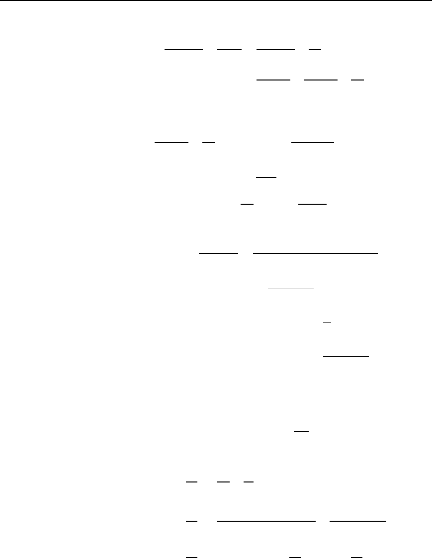
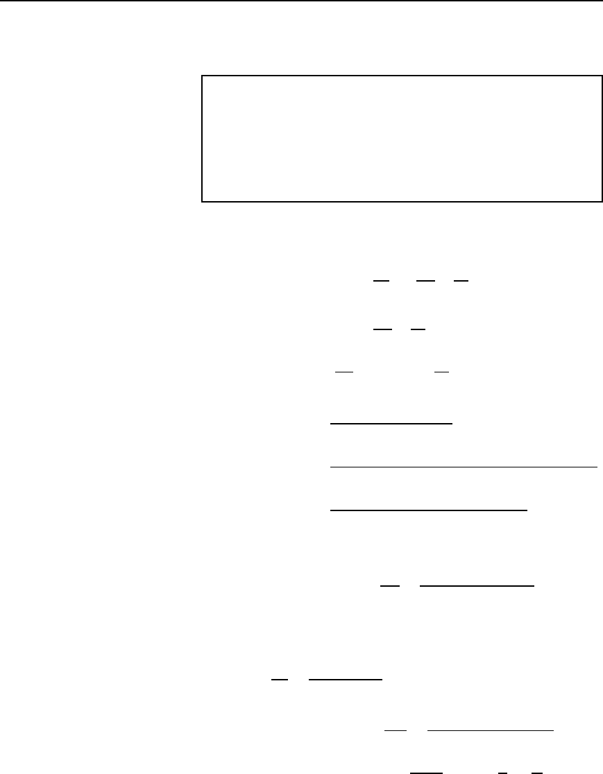
Problem 2. In the parallel network of Figure 29.6, inductance,
L D 100 mH and capacitance, C D 40
µF. Determine the resonant
frequency for the network if (a) R
L
D 0 and (b) R
L
D 30
Figure 29.6
522 Electrical Circuit Theory and Technology
Total circuit admittance,
Y D
1
R
L
C jX
L
C
1
jX
C
D
R
L
jX
L
R
2
L
C X
2
L
C
j
X
C
D
R
L
R
2
L
C X
2
L
jX
L
R
2
L
C X
2
L
C
j
X
C
The network is at resonance when the admittance is at a minimum value,
i.e., when the imaginary part is zero. Hence, at resonance,
X
L
R
2
L
C X
2
L
C
1
X
C
D 0orω
r
C D
ω
r
L
R
2
L
C ω
2
r
L
2
29.11
(a) When R
L
D 0, ω
r
C D
ω
r
L
ω
2
r
L
2
from which, ω
2
r
D
1
LC
and ω
r
D
1
p
LC
Hence resonant frequency,
f
r
D
1
2
p
LC
D
1
2
100 ð 10
3
ð 40 ð10
6
D 79.6Hz
(b) When R
L
D 30, ω
r
C D
ω
r
L
30
2
C ω
2
r
L
2
from equation (29.11) above
from which, 30
2
C ω
2
r
L
2
D
L
C
i.e., ω
2
r
100 ð 10
3
2
D
100 ð 10
3
40 ð 10
6
900
i.e., ω
2
r
0.01 D 2500 900 D 1600
Thus, ω
2
r
D 1600/0.01 D 160000 and ω
r
D
p
160000 D 400 rad/s
Hence resonant frequency, f
r
D
400
2
D 63.7Hz
[Alternatively, from equation (29.3),
f
r
D
1
2
1
LC
R
2
L
2
D
1
2
1
100 ð 10
3
40 ð 10
6
30
2
100 ð 10
3
2
D
1
2
p
250 00090 000D
1
2
p
160000D
1
2
400 D63.7Hz]
Parallel resonance and Q-factor 523
Hence, as the resistance of a coil increases, the resonant frequency
decreases in the circuit of Figure 29.6.
Problem 3. A coil of inductance 120 mH and resistance 150
is connected in parallel with a variable capacitor across a 20 V,
4 kHz supply. Determine for the condition when the supply current
is a minimum, (a) the capacitance of the capacitor, (b) the dynamic
resistance, (c) the supply current, (d) the Q-factor, (e) the band-
width, (f) the upper and lower 3 dB frequencies, and (g) the value
of the circuit impedance at the 3 dB frequencies.
(a) The supply current is a minimum when the parallel network is at
resonance.
Resonant frequency, f
r
D
1
2
1
LC
R
2
L
2
from equation (29.3),
from which, 2f
r
2
D
1
LC
R
2
L
2
Hence
1
LC
D 2f
r
2
C
R
2
L
2
and
capacitance C D
1
L[2f
r
2
C R
2
/L
2
]
D
1
120 ð 10
3
[24000
2
C 150
2
/120 ð 10
3
2
]
D
1
0.12631.65 ð 10
6
C 1.5625 ð10
6
D 0.01316 mF or 13.16 nF
(b) Dynamic resistance, R
D
D
L
CR
D
120 ð 10
3
13.16 ð 10
9
150
D 60.79 kZ
(c) Supply current at resonance,
I
r
D
V
R
D
D
20
60.79 ð10
3
D 0.329 mA or 329 mA
(d) Q-factor at resonance, Q
r
D
ω
r
L
R
D
24000120 ð 10
3
150
D 20.11
[Note that the expressions Q
r
D
1
ω
r
CR
or Q
r
D
1
R
L
C
524 Electrical Circuit Theory and Technology
used for the R–L –C series circuit may also be used in parallel
circuits when the resistance of the coil is much smaller than the
inductive reactance of the coil.
In this case R D 150 and X
L
D 24000120 ð 10
3
D 3016 .
Hence, alternatively,
Q
r
D
1
ω
r
CR
D
1
2400013.16 ð 10
9
150
D 20.16
or Q
r
D
1
R
L
C
D
1
150
120 ð 10
3
13.16 ð10
9
D 20.13]
(e) If the lower and upper 3 dB frequencies are f
1
and f
2
respectively
then the bandwidth is f
2
f
1
. Q-factor at resonance is given by
Q
r
D f
r
/f
2
f
1
, from which, bandwidth,
.f
2
− f
1
/ D
f
r
Q
r
D
4000
20.11
D 199 Hz
(f) Resonant frequency, f
r
D
p
f
1
f
2
, from which
f
1
f
2
D f
2
r
D 4000
2
D 16 ð 10
6
29.12
Also, from part (e), f
2
f
1
D 199 29.13
From equation (29.12), f
1
D
16 ð 10
6
f
2
Substituting in equation (29.13) gives: f
2
16 ð 10
6
f
2
D 199
i.e., f
2
2
16 ð 10
6
D 199f
2
from which,
f
2
2
199f
2
16 ð 10
6
D 0.
Solving this quadratic equation gives:
f
2
D
199 š
[199
2
416 ð10
6
]
2
D
199 š 8002.5
2
i.e., the upper 3 dB frequency, f
2
= 4100 Hz (neglecting the nega-
tive answer).
From equation (29.12),
the lower
−3 dB frequency, f
1
D
10 ð 10
6
f
2
D
16 ð 10
6
4100
D 3900 Hz
Parallel resonance and Q-factor 525
(Note that f
1
and f
2
are equally displaced about the resonant
frequency, f
r
, as they always will be when Q is greater than about
10— just as for a series circuit)
(g) The value of the circuit impedance, Z,atthe3 dB frequencies is
given by
Z D
1
p
2
Z
r
where Z
r
is the impedance at resonance.
The impedance at resonance Z
r
D R
D
, the dynamic resistance.
Hence impedance at the
−3 dB frequencies D
1
p
2
60.79 ð 10
3
D 42.99 kZ
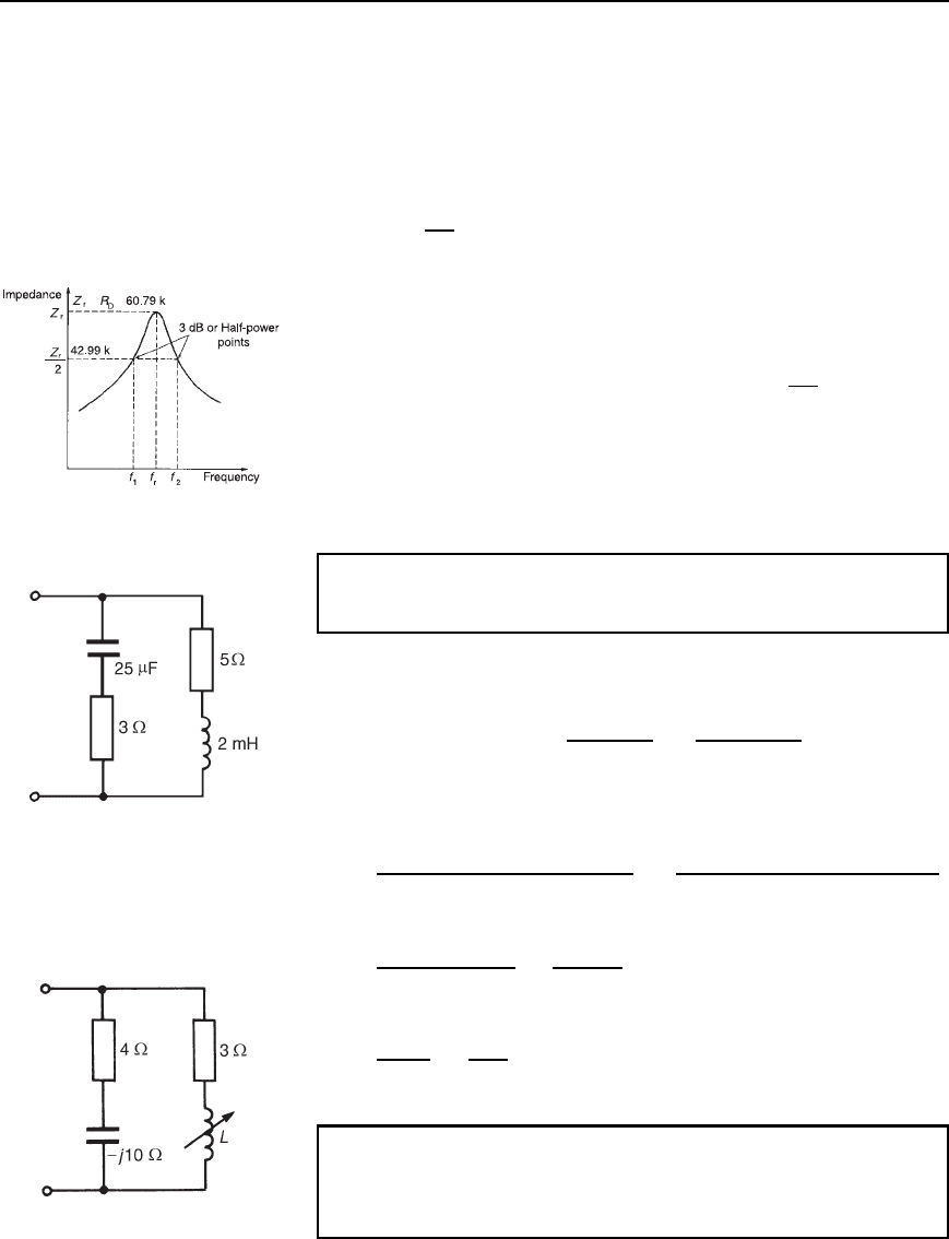
Figure 29.7 shows impedance plotted against frequency for the
circuit in the region of the resonant frequency.
== Ω
Ω
−
√
Figure 29.7
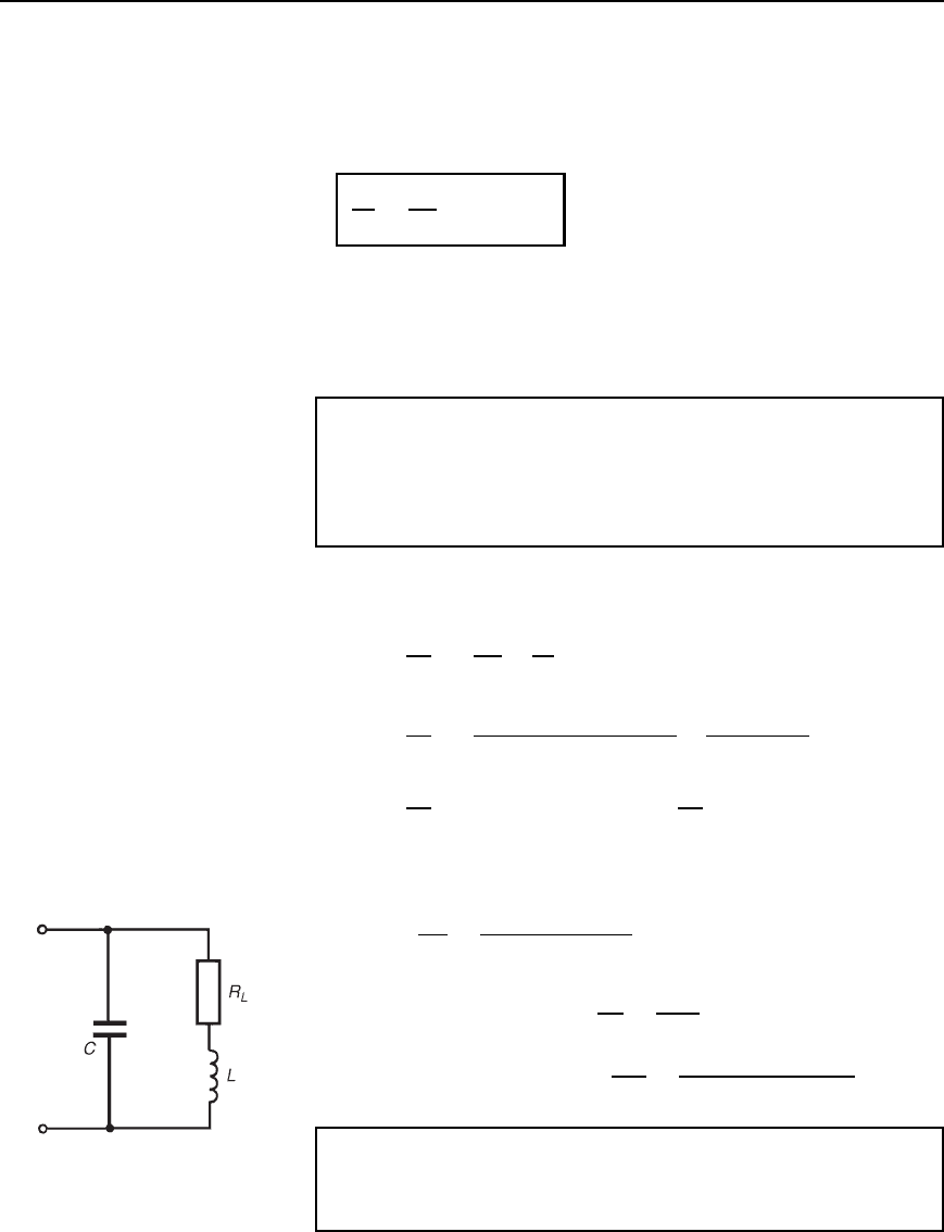
Problem 4. A two-branch parallel network is shown in
Figure 29.8. Determine the resonant frequency of the network.
Figure 29.8
From equation (29.6),
resonant frequency, f
r
D
1
2
p
LC
R
2
L
L/C
R
2
C
L/C
where R
L
D 5 , R
C
D 3 , L D 2mHandC D 25 µF. Thus
f
r
D
1
2
[2 ð 10
3
25 ð 10
6
]
5
2
2 ð 10
3
/25 ð 10
6
3
2
2 ð 10
3
/25 ð 10
6
D
1
2
5 ð 10
8
25 80
9 80
D
10
4
2
p
5
55
71
D 626.5Hz
Problem 5. Determine for the parallel network shown in
Figure 29.9 the values of inductance L for which the network is
resonant at a frequency of 1 kHz.
Figure 29.9
526 Electrical Circuit Theory and Technology
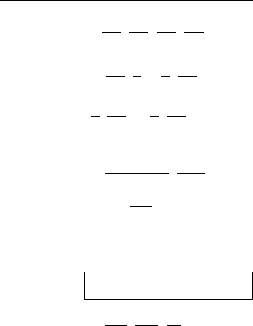
The total network admittance, Y, is given by
Y D
1
3 C jX
L
C
1
4 j10
D
3 jX
L
3
2
C X
2
L
C
4 C j10
4
2
C 10
2
D
3
3
2
C X
2
L
jX
L
3
2
C X
2
L
C
4
116
C
j10
116
D
3
3
2
C X
2
L
C
4
116
C j
10
116
X
L
3
2
C X
2
L
Resonance occurs when the admittance is a minimum, i.e., when the
imaginary part of Y is zero. Hence, at resonance,
10
116
X
L
3
2
C X
2
L
D 0 i.e.,
10
116
D
X
L
3
2
C X
2
L
Therefore 109 C X
2
L
D 116 X
L
i.e., 10 X
2
L
116 X
L
C 90 D 0
from which, X
2
L
11.6 X
L
C 9 D 0
Solving the quadratic equation gives:
X
L
D
11.6 š
[11.6
2
49]
2
D
11.6 š 9.93
2
i.e., X
L
D 10.765 or 0.835 . Hence 10.765 D 2f
r
L
1
, from which,
inductance L
1
D
10.765
21000
D 1.71 mH
and 0.835 D 2f
r
L
2
from which,
inductance, L
2
D
0.835
21000
D 0.13 mH
Thus the conditions for the circuit of Figure 29.9 to be resonant are
that inductance L is either 1.71 mH or 0.13 mH
Problem 6. A capacitor having a Q-factor of 300 is connected in
parallel with a coil having a Q-factor of 60. Determine the overall
Q-factor of the parallel combination.
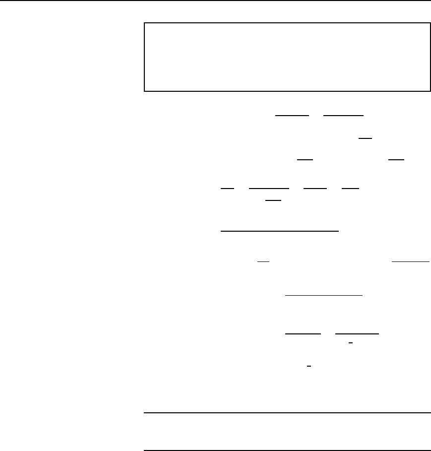
From equation (29.9), the overall Q-factor is given by:
Q
T
D
Q
L
Q
C
Q
L
C Q
C
D
60300
60 C 300
D
18000
360
D 50
Parallel resonance and Q-factor 527
Problem 7. In an LR–C network, the capacitance is 10.61 nF, the
bandwidth is 500 Hz and the resonant frequency is 150 kHz. Deter-
mine for the circuit (a) the Q-factor, (b) the dynamic resistance, and
(c) the magnitude of the impedance when the supply frequency is
0.4% greater than the tuned frequency.
(a) From equation (29.7), Q D
f
r
f
2
f
1
D
150 ð 10
3
500
D 300
(b) From equation (29.4), dynamic resistance, R
D
D
L
CR
Also, in an LR–C network, Q D
ω
r
L
R
from which, R D
ω
r
L
Q
Hence, R
D
D
L
CR
D
L
C
ω
r
L
Q
D
LQ
Cω
r
L
D
Q
ω
r
C
D
300
2150 ð 10
3
10.61 ð 10
9
D 30 kZ
(c) From equation (29.10),
R
D
Z
D 1 C j2υQ from which, Z D
R
D
1 C j2υQ
υ D 0.4% D 0.004 hence Z D
30 ð 10
3
1 C j20.004300
D
30 ð 10
3
1 C j2.4
D
30 ð 10
3
2.6
6
67.38
°
D 11.54
6
67.38
°
k
Hence the magnitude of the impedance when the frequency is 0.4%
greater than the tuned frequency is 11.54 kZ.
Further problems on parallel resonance may be found in the Section 29.6
following, problems 1 to 14.
29.6 Further problems
on parallel resonance and
Q-factor
1 A coil of resistance 20 and inductance 100 mH is connected in
parallel with a 50
µF capacitor across a 30 V variable-frequency
supply. Determine (a) the resonant frequency of the circuit, (b) the
dynamic resistance, (c) the current at resonance, and (d) the circuit
Q-factor at resonance. [(a) 63.66 Hz (b) 100 (c) 0.30 A (d) 2]
2 A 25 V, 2.5 kHz supply is connected to a network comprising a
variable capacitor in parallel with a coil of resistance 250 and
inductance 80 mH. Determine for the condition when the supply
