Bird J. Electrical Circuit Theory and Technology
Подождите немного. Документ загружается.

608 Electrical Circuit Theory and Technology
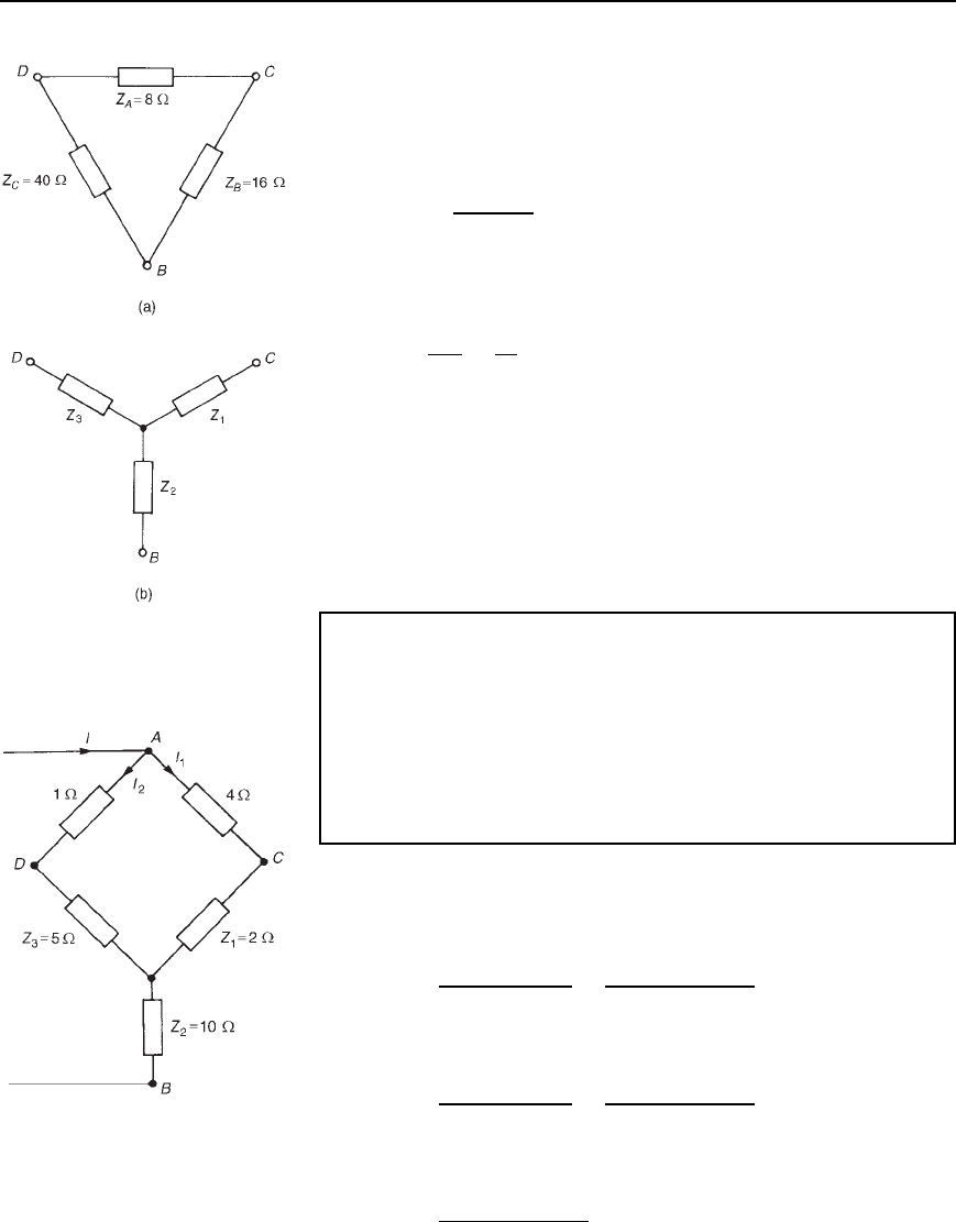
Figure 34.13
The network of Figure 34.12 may thus be redrawn as shown in
Figure 34.14. The 4 and 2 resistances are in series with each
other, as are the 1 and 5 resistors. Hence the equivalent network
is as shown in Figure 34.15. The total equivalent resistance across
terminals A and B is given by
R
AB
D
66
6 C 6
C 10 D 13 Z
(b) Current supplied by the 52 V source, i.e., current I in Figure 34.15,
is given by
I D
V
Z
AB
D
52
13
D 4A
(c) From Figure 34.15, current I
1
D [6/6 C 6]I D 2 A, and current
I
2
D 2 A also. From Figure 34.14, p.d. across AC, V
AC
D I
1
4 D
8 V and p.d. across AD, V
AD
D I
2
1 D 2 V. Hence p.d. between
C and D (i.e., p.d. across the 8 resistance of Figure 34.12) is given
by 8 2 D 6V.
Thus the current in the 8 Z resistance is given by V
CD
/8 D 6/8 D
0.75 A
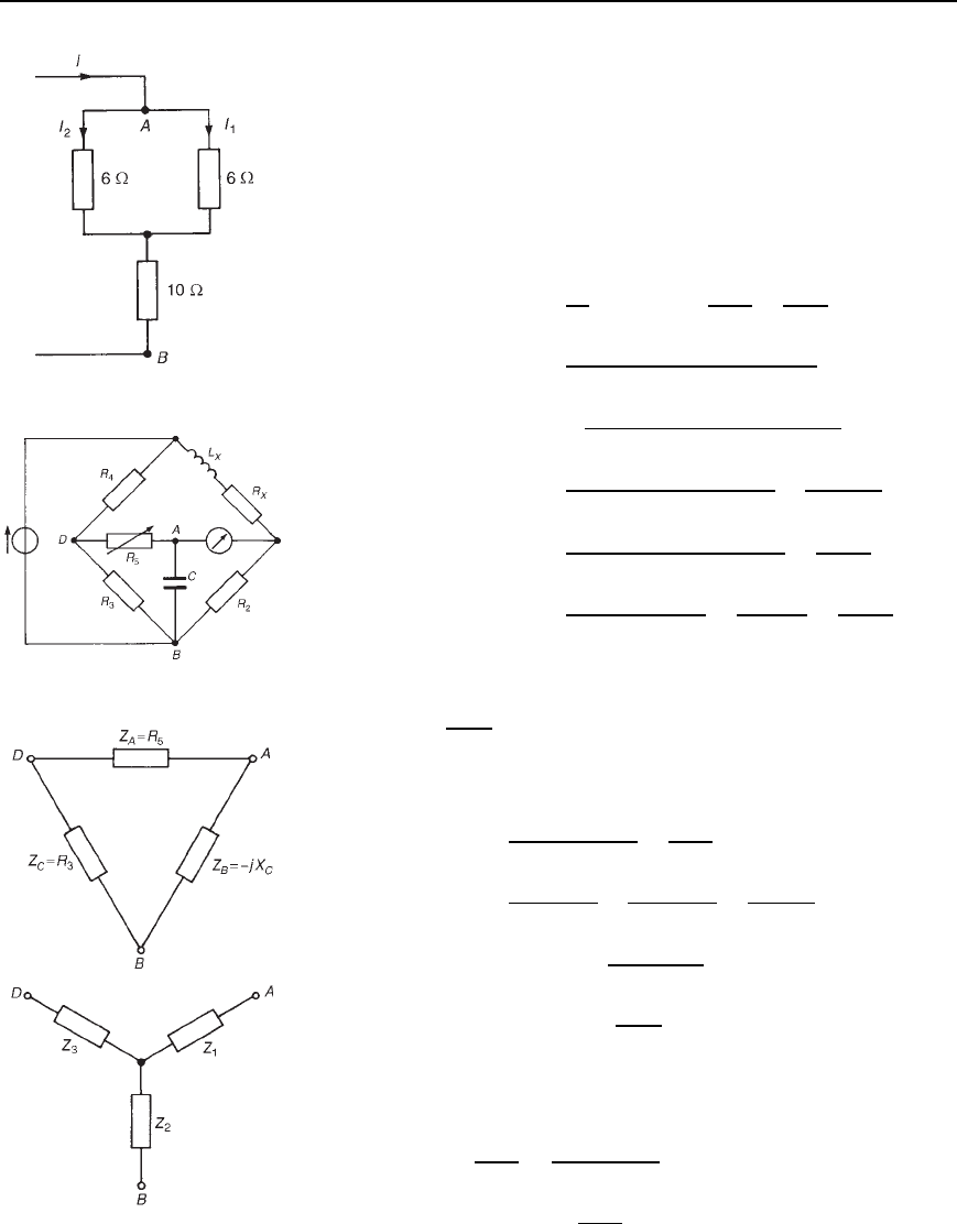
Problem 4. Figure 34.16 shows an Anderson bridge used
to measure, with high accuracy, inductance L
X
and series
resistance R
X
(a) Transform the delta ABD into its equivalent star connection
and hence determine the balance equations for R
X
and L
X
(b) If R
2
D R
3
D 1k, R
4
D 500 , R
5
D 200 and C D 2 µF,
determine the values of R
X
and L
X
at balance.
(a) The delta ABD is redrawn separately in Figure 34.17, together with
its equivalent star connection comprising impedances Z
1
, Z
2
and Z
3
.
From equation (34.7),
Z
1
D
R
5
jX
C
R
5
jX
C
C R
3
D
jR
5
X
C
R
3
C R
5
jX
C
From equation (34.8),
Z
2
D
jX
C
R
3
R
5
jX
C
C R
3
D
jR
3
X
C
R
3
C R
5
jX
C
From equation (34.9),
Z
3
D
R
5
R
3
R
3
C R
5
jX
C
Figure 34.14
Delta-star and star-delta transformations 609
Figure 34.15
The network of Figure 34.16 is redrawn with the star replacing
the delta as shown in Figure 34.18, and further simplified in
Figure 34.19. (Note that impedance Z
1
does not affect the balance
of the bridge since it is in series with the detector.)
Figure 34.16
At balance,
R
X
C jX
L
X
Z
2
D R
2
R
4
C Z
3
from Chapter 27,
from which,
R
X
C jX
L
X
D
R
2
Z
2
R
4
C Z
3
D
R
2
R
4
Z
2
C
R
2
Z
3
Z
2
D
R
2
R
4
jR
3
X
C
/R
3
C R
5
jX
C
C
R
2
R
5
R
3
/R
3
C R
5
jX
C
jR
3
X
C
/R
3
C R
5
jX
C
D
R
2
R
4
R
3
C R
5
jX
C
jR
3
X
C
C
R
2
R
5
R
3
jR
3
X
C
D
jR
2
R
4
R
3
C R
5
jX
C
R
3
X
C
C
jR
2
R
5
X
C
i.e., R
X
C jX
L
X
D
jR
2
R
4
R
3
C R
5
R
3
X
C
C
R
2
R
4
X
C
R
3
X
C
C
jR
2
R
5
X
C
Equating the real parts gives:
R
X
=
R
2
R
4
R
3
Equating the imaginary parts gives:
X
L
X
D
R
2
R
4
R
3
C R
5
R
3
X
C
C
R
2
R
5
X
C
i.e., ωL
X
D
R
2
R
4
R
3
R
3
1/ωC
C
R
2
R
4
R
5
R
3
1/ωC
C
R
2
R
5
1/ωC
D ωCR
2
R
4
C
ωCR
2
R
4
R
5
R
3
C ωCR
2
R
5
Hence L
X
D R
2
C
R
4
Y
R
4
R
5
R
3
Y R
5
(b) When R
2
D R
3
D 1k, R
4
D 500 , R
5
D 200 and C D 2 µF,
then, at balance
R
X
D
R
2
R
4
R
3
D
1000500
1000
D 500 Z
and L
X
D R
2
C
R
4
C
R
4
R
5
R
3
C R
5
Figure 34.17
610 Electrical Circuit Theory and Technology
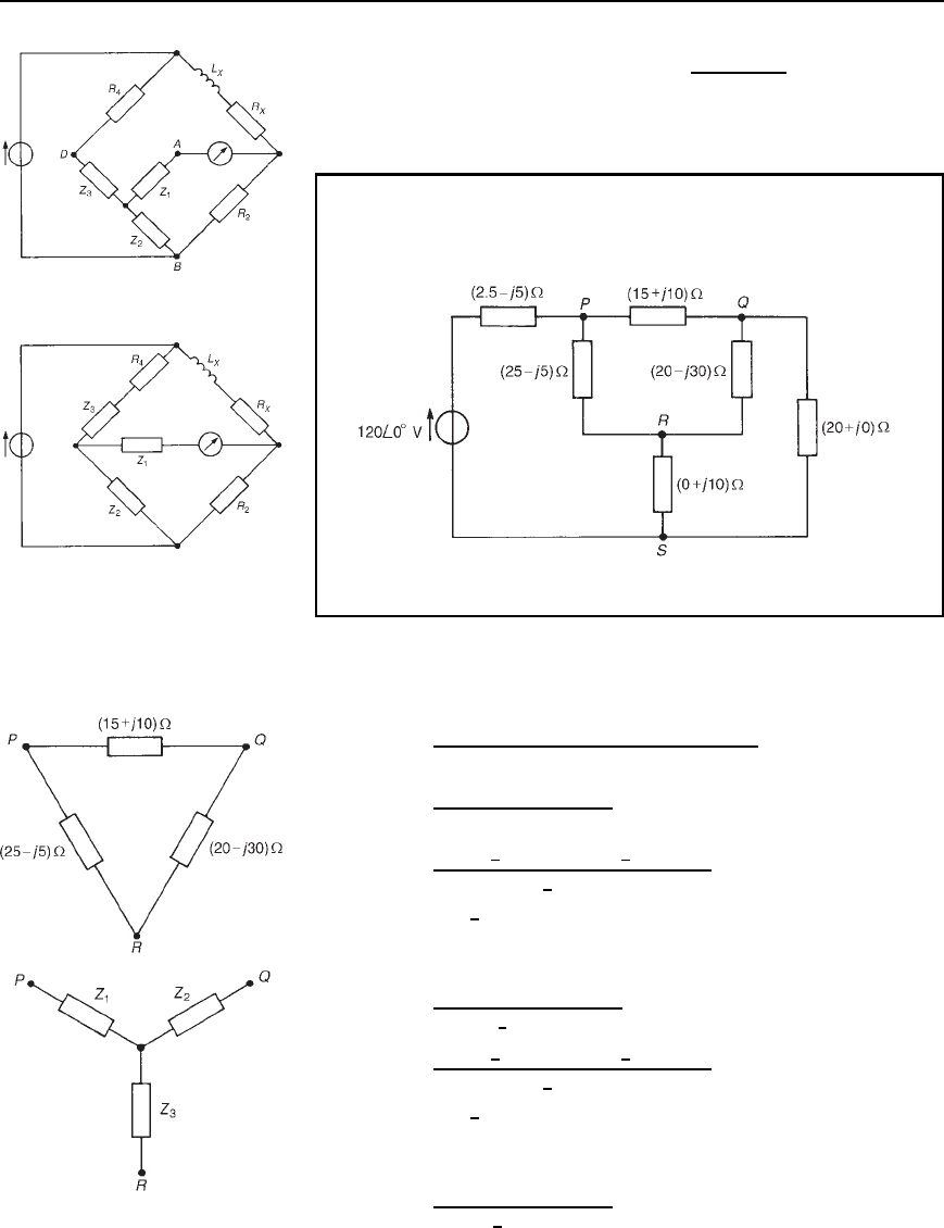
Figure 34.18
D 10002 ð 10
6
500 C
500200
1000
C 200
D 1.60 H
Figure 34.19
Problem 5. For the network shown in Figure 34.20, determine
(a) the current flowing in the 0 C j10 impedance, and (b) the
power dissipated in the 20 C j0 impedance.
Figure 34.20
(a) The network may initially be simplified by transforming the delta
PQR to its equivalent star connection as represented by impedances
Z
1
, Z
2
and Z
3
in Figure 34.21. From equation (34.7),
Z
1
D
15 C j1025 j5
15 C j10 C 25 j5 C 20 j30
D
15 C j1025 j5
60 j25
D
18.03
6
33.69
°
25.50
6
11.31
°
65
6
22.62
°
D 7.07
6
45
°
or 5 Cj5
From equation (34.8),
Z
2
D
15 C j1020 j30
65
6
22.62
°
D
18.03
6
33.69
°
36.06
6
56.31
°
65
6
22.62
°
D 10.0
6
0
°
or 10 Cj0
From equation (34.9),
Z
3
D
25 j520 j30
65
6
22.62
°
Figure 34.21
Delta-star and star-delta transformations 611
D
25.50
6
11.31
°
36.06
6
56.31
°
65
6
22.62
°
D 14.15
6
45
°
or 10 j10
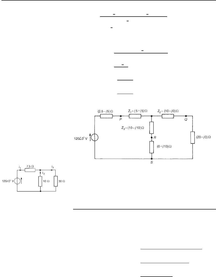
The network is shown redrawn in Figure 34.22 and further simplified
in Figure 34.23, from which,
current I
1
D
120
6
0
°
7.5 C 1030/10 C 30
D
120
6
0
°
15
D 8A
current I
2
D
10
10 C 30
8 D 2A
current I
3
D
30
10 C 30
8 D 6A
Figure 34.22
The current flowing in the 0 C j10 impedance of Figure 34.20
is the current I
3
shown in Figure 34.23, i.e., 6A
Figure 34.23
(b) The power P dissipated in the 20 C j0 impedance of
Figure 34.20 is given by P D I
2
2
20 D 2
2
20 D 80 W
34.4 Star-delta
transformation
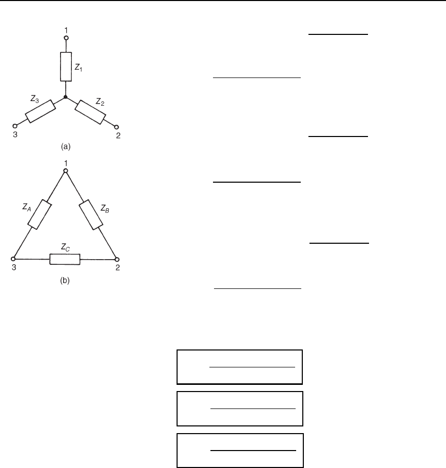
It is possible to replace the star section shown in Figure 34.24(a) by an
equivalent delta section as shown in Figure 34.24(b). Such a transforma-
tion is also known as a ‘T to transformation’.
From equations (34.7), (34.8) and (34.9),
Z
1
Z
2
C Z
2
Z
3
C Z
3
Z
1
D
Z
A
Z
2
B
Z
C
C Z
A
Z
B
Z
2
C
C Z
2
A
Z
B
Z
C
Z
A
C Z
B
C Z
C
2
D
Z
A
Z
B
Z
C
Z
B
C Z
C
C Z
A
Z
A
C Z
B
C Z
C
2
D
Z
A
Z
B
Z
C
Z
A
C Z
B
C Z
C
34.10
612 Electrical Circuit Theory and Technology
Figure 34.24
i.e., Z
1
Z
2
C Z
2
Z
3
C Z
3
Z
1
D Z
A
Z
B
Z
C
Z
A
C Z
B
C Z
C
D Z
A
Z
2
from equation (34.8)
Hence Z
A
D
Z
1
Z
2
C Z
2
Z
3
C Z
3
Z
1
Z
2
From equation (34.10),
Z
1
Z
2
C Z
2
Z
3
C Z
3
Z
1
D Z
B
Z
A
Z
C
Z
A
C Z
B
C Z
C
D Z
B
Z
3
from equation (34.9)
Hence Z
B
D
Z
1
Z
2
C Z
2
Z
3
C Z
3
Z
1
Z
3
Also from equation (34.10),
Z
1
Z
2
C Z
2
Z
3
C Z
3
Z
1
D Z
C
Z
A
Z
B
Z
A
C Z
B
C Z
C
D Z
C
Z
1
from equation (34.7)
Hence Z
C
D
Z
1
Z
2
C Z
2
Z
3
C Z
3
Z
1
Z
1
Summarizing, the delta section shown in Figure 34.24(b) is equivalent to
the star section shown in Figure 34.24(a) when
Z
A
=
Z
1
Z
2
Y Z
2
Z
3
Y Z
3
Z
1
Z
2
34.11
Z
B
=
Z
1
Z
2
Y Z
2
Z
3
Y Z
3
Z
1
Z
3
34.12
and
Z
C
=
Z
1
Z
2
Y Z
2
Z
3
Y Z
3
Z
1
Z
1
34.13
It is noted that the numerator in each expression is the sum of the products
of the star impedances taken in pairs. The denominator of the expression
for Z
A
, which is connected between terminals 1 and 3 of Figure 34.24(b),
is Z
2
, which is connected to terminal 2 of Figure 34.24(a). Similarly, the
denominator of the expression for Z
B
which is connected between termi-
nals 1 and 2 of Figure 34.24(b), is Z
3
, which is connected to terminal 3
of Figure 34.24(a). Also the denominator of the expression for Z
C
which
is connected between terminals 2 and 3 of Figure 34.24(b), is Z
1
, which
is connected to terminal 1 of Figure 34.24(a).
Delta-star and star-delta transformations 613
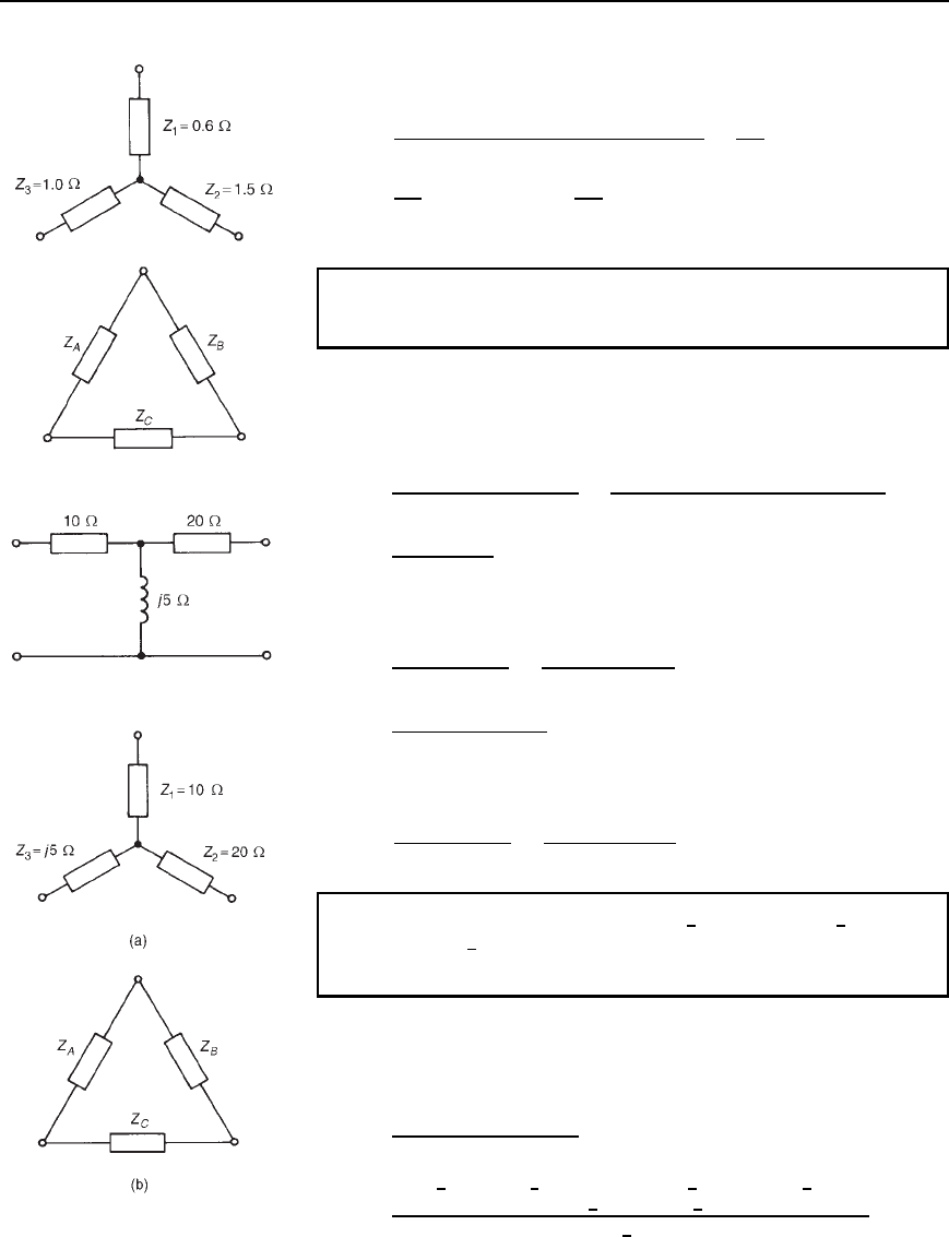
Figure 34.25
Thus, for example, the delta equivalent of the resistive star circuit
shown in Figure 34.25 is given by:
Z
A
D
0.61.5 C 1.51.0 C 1.00.6
1.5
D
3.0
1.5
D 2 Z,
Z
B
D
3.0
1.0
D 3 Z, Z
C
D
3.0
0.6
D 5 Z
Problem 6. Determine the delta-connected equivalent network for
the star-connected impedances shown in Figure 34.26
Figure 34.26
Figure 34.27(a) shows the network of Figure 34.26 redrawn and
Figure 34.27(b) shows the equivalent delta connection containing
impedances Z
A
, Z
B
and Z
C
. From equation (34.11),
Z
A
D
Z
1
Z
2
C Z
2
Z
3
C Z
3
Z
1
Z
2
D
1020 C 20j5 C j510
20
D
200 C j150
20
D .10 Y j7.5/Z
From equation (34.12),
Z
B
D
200 C j150
Z
3
D
200 C j150
j5
D
j5200 C j150
25
D .30
− j40/Z
From equation (34.13),
Z
C
D
200 C j150
Z
1
D
200 C j150
10
D .20 Y j15/Z
Problem 7. Three impedances, Z
1
D100
6
0
°
, Z
2
D63.25
6
18.43
°
and Z
3
D 100
6
90
°
are connected in star. Convert the star to
an equivalent delta connection.
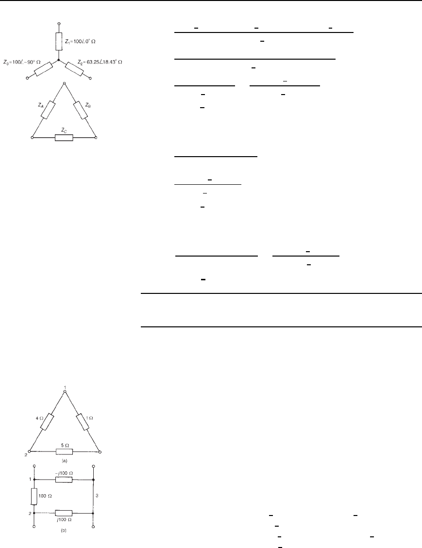
The star-connected network and the equivalent delta network comprising
impedances Z
A
, Z
B
and Z
C
are shown in Figure 34.28. From
equation (34.11),
Z
A
D
Z
1
Z
2
C Z
2
Z
3
C Z
3
Z
1
Z
2
D
100
6
0
°
63.25
6
18.43
°
C 63.25
6
18.43
°
100
6
90
°
C100
6
90
°
100
6
0
°
63.25
6
18.43
°
Figure 34.27
614 Electrical Circuit Theory and Technology
Figure 34.28
D
6325
6
18.43
°
C 6325
6
71.57
°
C 10000
6
90
°
63.25
6
18.43
°
D
6000 C j2000 C 2000 j6000 j10000
63.25
6
18.43
°
D
8000 j14 000
63.25
6
18.43
°
D
16124.5
6
60.26
°
63.25
6
18.43
°
D 254.93
66
−78.69
°
Z or .50 − j250/Z
From equation (34.12),
Z
B
D
Z
1
Z
2
C Z
2
Z
3
C Z
3
Z
1
Z
3
D
16124.5
6
60.26
100
6
90
°
D 161.25
66
29.74
°
Z or .140 Y j80/Z
From equation (34.13),
Z
C
D
Z
1
Z
2
C Z
2
Z
3
C Z
3
Z
1
Z
1
D
16124.5
6
60.26
100
6
0
°
D 161.25
66
−60.26
°
Z or .80 Y j140/Z
Further problems on delta-star and star-delta transformations may be
found in Section 34.5 following, problems 1 to 10.
34.5 Further problems
on delta-star and
star-delta transformations
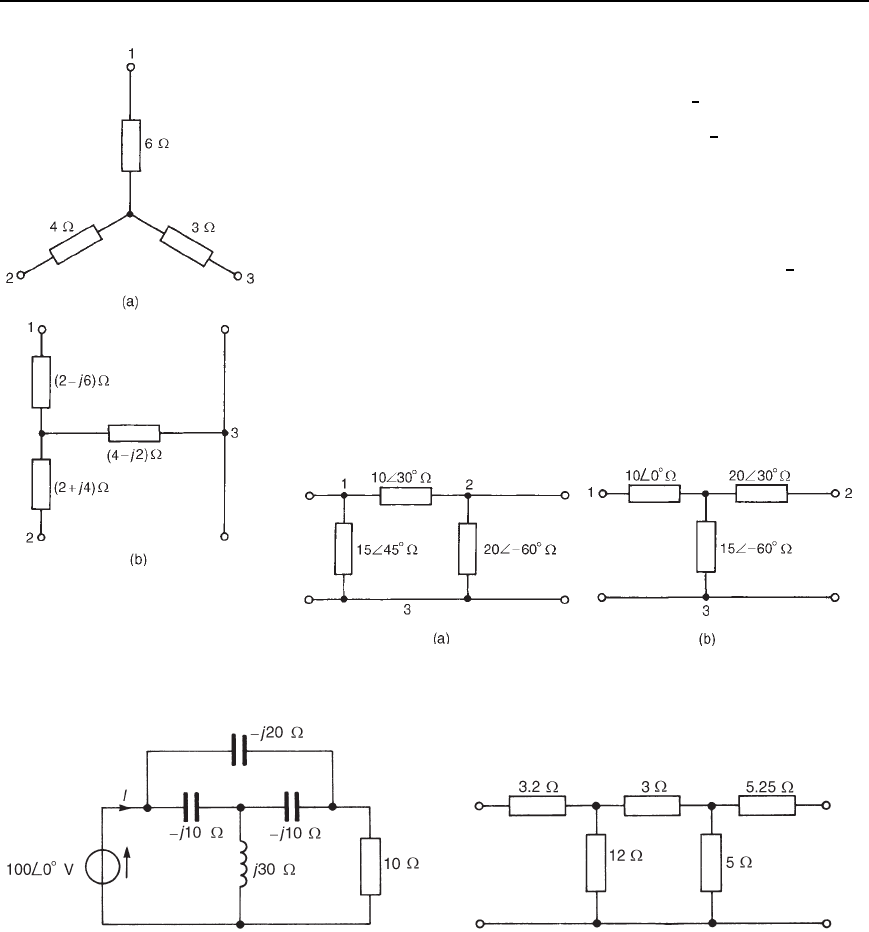
1 Transform the delta connected networks shown in Figure 34.29 to
their equivalent star-connected networks.
[(a) Z
1
D 0.4 , Z
2
D 2 , Z
3
D 0.5
(b) Z
1
Dj100 , Z
2
D j100 , Z
3
D 100 ]
2 Determine the delta-connected equivalent networks for the star-
connected impedances shown in Figure 34.30
[(a) Z
12
D 18 , Z
23
D 9 , Z
31
D 13.5
(b) Z
12
D 10 C j0, Z
23
D 5 C j5,
Z
31
D 0 j10]
3 (a) Transform the network shown in Figure 34.31(a) to its equiv-
alent star-connected network.
(b) Change the T-connected network shown in Figure 34.31(b) to
its equivalent delta-connected network.
[(a) Z
1
D 5.12
6
78.35
°
, Z
2
D 6.82
6
26.65
°
,
Z
3
D 10.23
6
11.65
°
(b) Z
12
D 35.93
6
40.50
°
, Z
23
D 53.89
6
19.50
°
,
Z
31
D 26.95
6
49.50
°
]
Figure 34.29
Delta-star and star-delta transformations 615
Figure 34.30
4 For the network shown in Figure 34.32 determine (a) current I,and
(b) the power dissipated in the 10 resistance.
[(a) 7.32
6
24.06
°
A (b) 668 W]
5 (a) A delta-connected network contains three 24
6
60
°
impedances.
Determine the impedances of the equivalent star-connected
network.
(b) Three impedances, each of 2 Cj3, are connected in star.
Determine the impedances of the equivalent delta-connected
network.
[(a) Each impedance D 8
6
60
°
(b) Each impedance D 6 C j9]
6 (a) Derive the star-connected network of three impedances equiva-
lent to the network shown in Figure 34.33.
(b) Obtain the delta-connected equivalent network for Figure 34.33.
[(a) 5 , 6 , 3
(b) 21 , 12.6 , 10.5 ]
Figure 34.31
Figure 34.32 Figure 34.33
7 For the a.c. bridge network shown in Figure 34.34, transform the
delta-connected network ABC into an equivalent star, and hence deter-
mine the current flowing in the capacitor. [131 mA]
8 For the network shown in Figure 34.35 transform the delta-connected
network ABC to an equivalent star-connected network, convert the
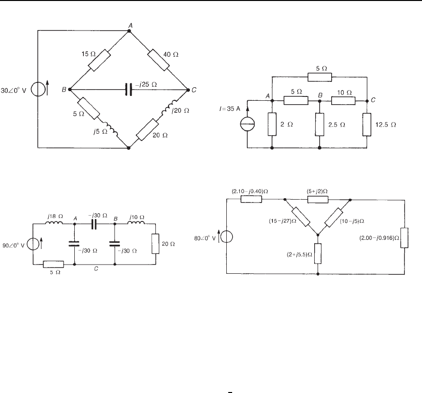
616 Electrical Circuit Theory and Technology
Figure 34.34 Figure 34.35
Figure 34.36 Figure 34.37
35 A, 2 Norton circuit to an equivalent Th
´
evenin circuit and hence
determine the p.d. across the 12.5 resistor. [31.25 V]
9 Transform the delta-connected network ABC shown in Figure 34.36
and hence determine the magnitude of the current flowing in the 20
resistance. [4.47 A]
10 For the network shown in Figure 34.37 determine (a) the current
supplied by the 80
6
0
°
V source, and (b) the power dissipated in the
2.00 j0.916 impedance. [(a) 9.73 A (b) 98.6 W]
35 Maximum power
transfer theorems and
impedance matching
At the end of this chapter you should be able to:
ž appreciate the conditions for maximum power transfer in a.c.
networks
ž apply the maximum power transfer theorems to a.c. networks
ž appreciate advantages of impedance matching in a.c. networks
ž perform calculations involving matching transformers for
impedance matching in a.c. networks
35.1 Maximum power
transfer theorems
A network that contains linear impedances and one or more voltage or
current sources can be reduced to a Th
´
evenin equivalent circuit as shown
in Chapter 33. When a load is connected to the terminals of this equivalent
circuit, power is transferred from the source to the load.
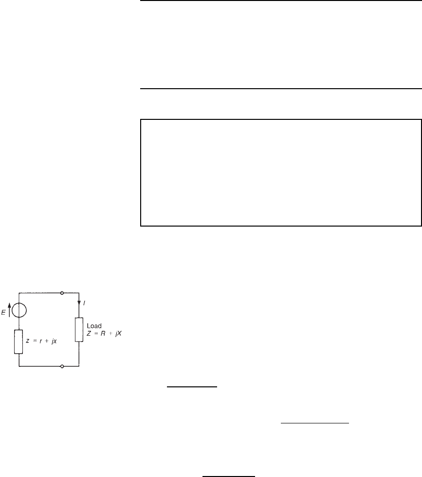
ATh
´
evenin equivalent circuit is shown in Figure 35.1 with source
internal impedance, z D r C jx and complex load Z D R C jX.
The maximum power transferred from the source to the load depends
on the following four conditions.
Figure 35.1
Condition 1. Let the load consist of a pure variable resistance R (i.e. let
X D 0). Then current I in the load is given by:
I D
E
r C R C jx
and the magnitude of current,
j
I
j
D
E
[r C R
2
C x
2
]
The active power P delivered to load R is given by
P D
j
I
j
2
R D
E
2
R
r C R
2
C x
2
To determine the value of R for maximum power transferred to the load,
P is differentiated with respect to R and then equated to zero (this being
the normal procedure for finding maximum or minimum values using
