Bird J. Electrical Circuit Theory and Technology
Подождите немного. Документ загружается.

468 Electrical Circuit Theory and Technology
Problem 3. A series circuit possesses resistance R and capaci-
tance C. The circuit dissipates a power of 1.732 kW and has a
power factor of 0.866 leading. If the applied voltage is given by
v D
141.4sin10
4
t C /9 volts, determine (a) the current flowing
and its phase, (b) the value of resistance R, and (c) the value of
capacitance C.
(a) Since v D 141.4 sin10
4
t C /9 volts, then 141.4 V represents the
maximum value, from which the rms voltage, V D 141.4/
p
2 D
100 V, and the phase angle of the voltage DC/9 rad or 20
°
leading. Hence as a phasor the voltage V is written as 100
66
20
°
V.
Power factor D 0.866 D cos, from which D arccos 0.866 D 30
°
.
Hence the angle between voltage and current is 30
°
.
Power P D VI cos . Hence 1732 D 100I cos 30
°
from which,
current, jIjD
1732
1000.866
D 20 A
Since the power factor is leading, the current phasor leads the
voltage— in this case by 30
°
. Since the voltage has a phase angle
of 20
°
,
current, I D 20
6
20
°
C 30
°
A D 20
66
50
°
A
(b) Impedance Z D
V
I
D
100
6
20
°
20
6
50
°
D 5
6
30
°
or 4.33 j2.5
Hence the resistance, R
= 4.33 Z and the capacitive reactance,
X
C
D 2.5 .
Alternatively, the resistance may be determined from active power,
P D I
2
R. Hence 1732 D 20
2
R, from which,
resistance R D
1732
20
2
D 4.33 Z
(c) Since
v D 141.4sin10
4
t C /9 volts, angular velocity
ω D 10
4
rad/s. Capacitive reactance, X
C
D 2.5 , thus
2.5 D
1
2fC
D
1
ωC
from which, capacitance, C D
1
2.5ω
D
1
2.510
4
F D 40 mF
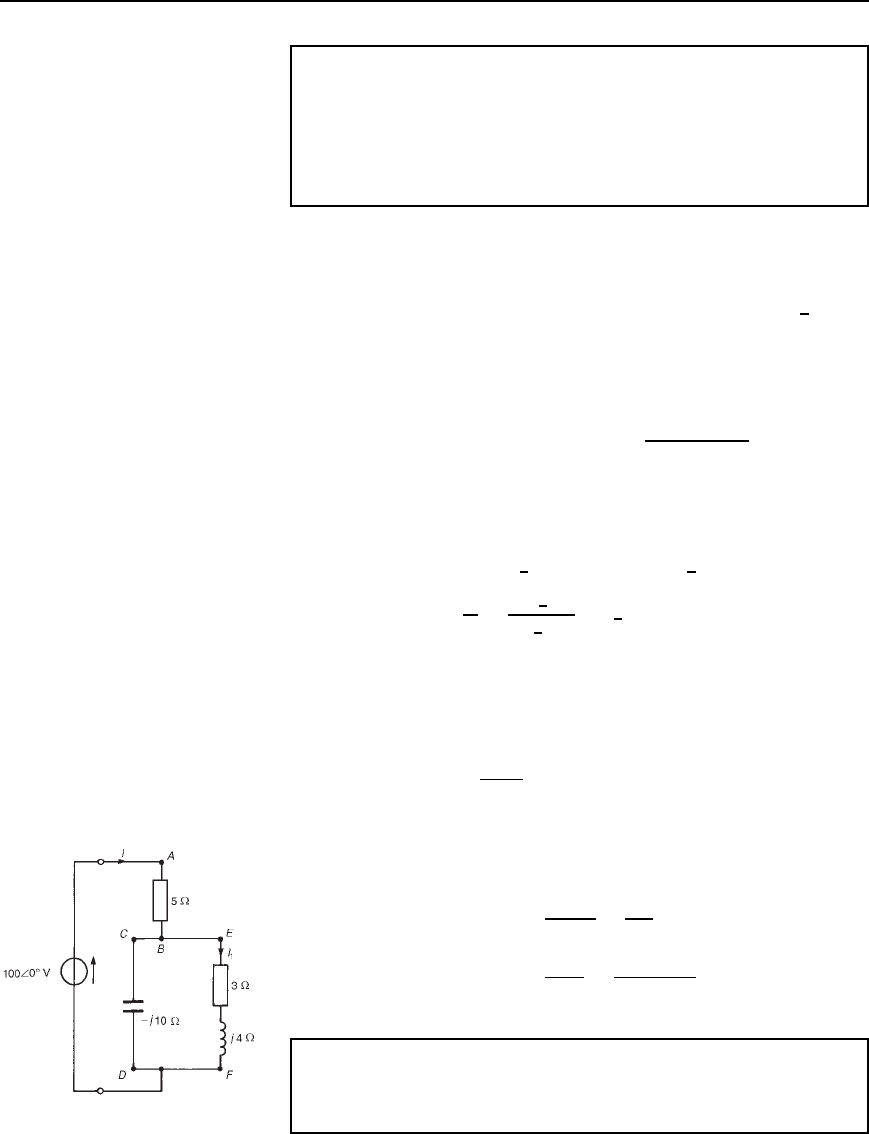
Problem 4. For the circuit shown in Figure 26.8, determine the
active power developed between points (a) A and B, (b) C and D,
(c) E and F.
Figure 26.8
Power in a.c. circuits 469
Circuit impedance, Z D 5 C
3 C j4j10
3 C j4 j10
D 5 C
40 j30
3 j6
D 5 C
50
6
36.87
°
6.71
6
63.43
°
D 5 C 7.45
6
26.56
°
D 5 C 6.66 C j3.33 D 11.66 Cj3.33 or
12.13
6
15.94
°
Current I D
V
Z
D
100
6
0
°
12.13
6
15.94
°
D 8.24
6
15.94
°
A
(a) Active power developed between points A and B D I
2
R D
8.24
2
5 D 339.5 W
(b) Active power developed between points C and D is zero, since no
power is developed in a pure capacitor.
(c) Current, I
1
D I
Z
CD
Z
CD
C Z
EF
D 8.24
6
15.94
°
j10
3 j6
D 8.24
6
15.94
°
10
6
90
°
6.71
6
63.43
°
D 12.28
6
42.51
°
A
Hence the active power developed between points E and F
D I
2
1
R D 12.28
2
3 D 452.4 W
[Check: Total active power developed D 339.5 C452.4 D 791.9W
or 792 W, correct to three significant figures.
Total active power, P D I
2
R
T
D 8.24
2
11.66 D 792 W (since
1l.66 is the total circuit equivalent resistance)
or P D VI cos D 1008.24 cos15.94
°
D 792 W]
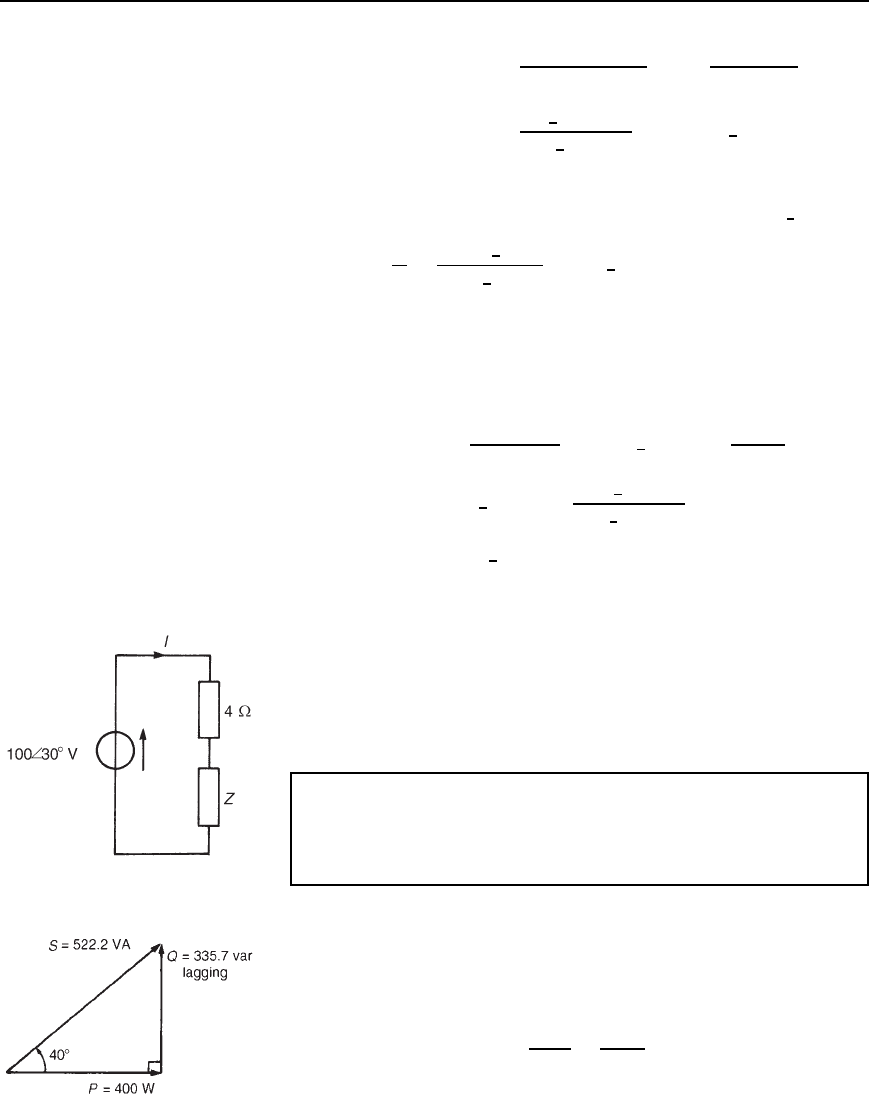
Problem 5. The circuit shown in Figure 26.9 dissipates an active
power of 400 W and has a power factor of 0.766 lagging. Determine
(a) the apparent power, (b) the reactive power, (c) the value and
phase of current I, and (d) the value of impedance Z.
Figure 26.9
Since power factor D 0.766 lagging, the circuit phase angle
D arccos 0.766, i.e., D 40
°
lagging which means that the current I
lags voltage V by 40
°
.
(a) Since power, P D VI cos , the magnitude of apparent power,
S D VI D
P
cos
D
400
0.766
D 522.2VA
(b) Reactive power Q D VI sin D 522.2sin 40
°
D 335.7 var lagg-
ing. (The reactive power is lagging since the circuit is inductive,
Figure 26.10
470 Electrical Circuit Theory and Technology
Figure 26.11 (a) Circuit
diagram (b) Phasor diagram
which is indicated by the lagging power factor.) The power triangle
is shown in Figure 26.10.
(c) Since VI D 522.2VA,
magnitude of current jIjD
522.2
V
D
522.2
100
D 5.222 A
Since the voltage is at a phase angle of 30
°
(see Figure 26.9)
and current lags voltage by 40
°
, the phase angle of current is
30
°
40
°
D10
°
. Hence current I = 5.222
66
−10
°
A
(d) Total circuit impedance Z
T
D
V
I
D
100
6
30
°
5.222
6
10
°
D 19.15
6
40
°
or 14.67 Cj12.31
Hence impedance Z D Z
T
4 D 14.67 C j12.31 4
D .10.67 Y j12.31/Z or 16.29
66
49.08
°
Z
Further problems on power in a.c. circuits may be found in Section 26.6,
problems 1 to 12, page 472.
26.5 Power factor
improvement
For a particular active power supplied, a high power factor reduces the
current flowing in a supply system and therefore reduces the cost of cables,
transformers, switchgear and generators, as mentioned in Section 16.7,
page 252. Supply authorities use tariffs which encourage consumers to
operate at a reasonably high power factor. One method of improving the
power factor of an inductive load is to connect a bank of capacitors in
parallel with the load. Capacitors are rated in reactive voltamperes and
the effect of the capacitors is to reduce the reactive power of the system
without changing the active power. Most residential and industrial loads on
a power system are inductive, i.e. they operate at a lagging power factor.
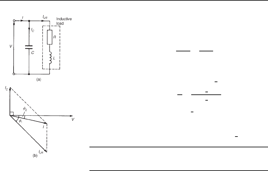
A simplified circuit diagram is shown in Figure 26.11(a) where a capac-
itor C is connected across an inductive load. Before the capacitor is
connected the circuit current is I
LR
and is shown lagging voltage V by
angle
1
in the phasor diagram of Figure 26.11(b). When the capacitor C
is connected it takes a current I
C
which is shown in the phasor diagram
leading voltage V by 90
°
. The supply current I in Figure 26.11(a) is now
the phasor sum of currents I
LR
and I
C
as shown in Figure 26.11(b). The
circuit phase angle, i.e., the angle between V and I, has been reduced from
1
to
2
and the power factor has been improved from cos
1
to cos
2
.
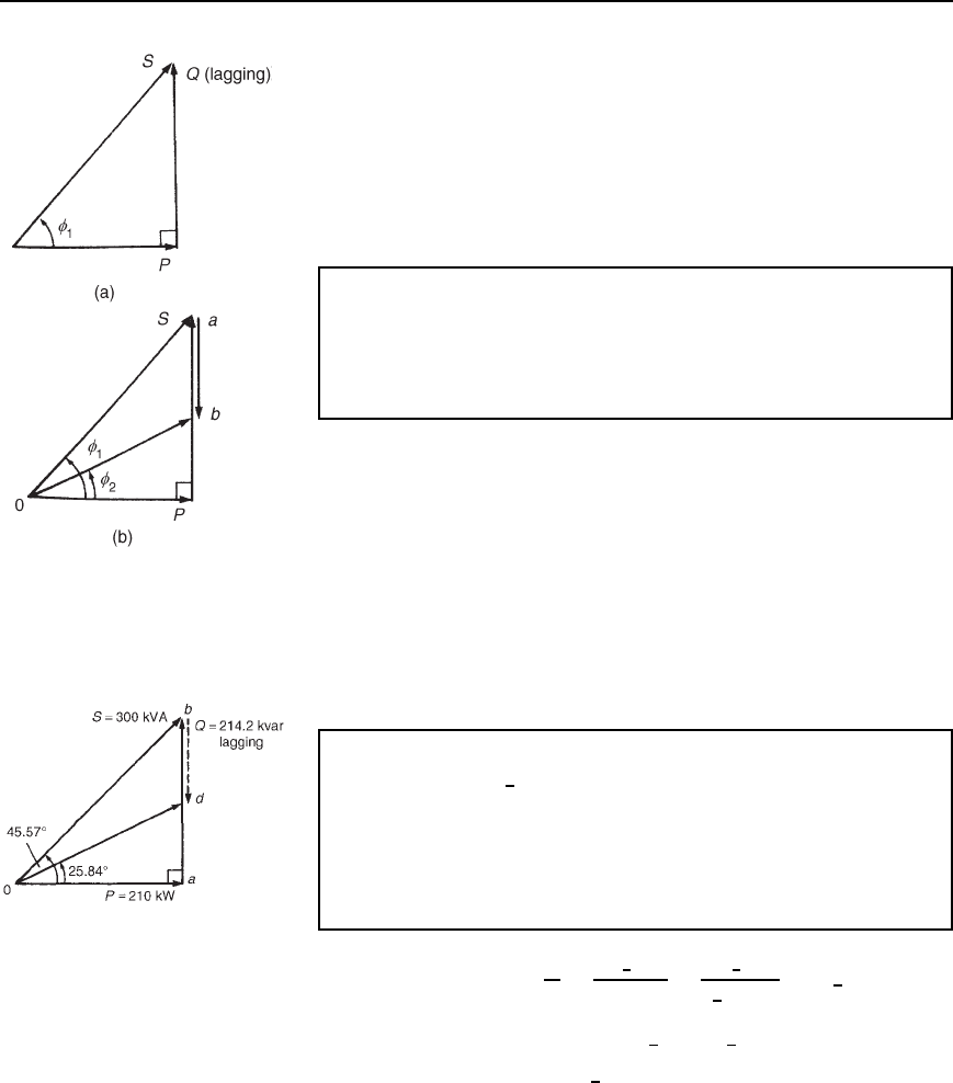
Figure 26.12(a) shows the power triangle for an inductive circuit with
a lagging power factor of cos
1
. In Figure 26.12(b), the angle
1
has
been reduced to
2
, i.e., the power factor has been improved from
cos
1
to cos
2
by introducing leading reactive voltamperes (shown as
length ab) which is achieved by connecting capacitance in parallel with
Power in a.c. circuits 471
Figure 26.12 Effect of
connecting capacitance in
parallel with the inductive load
the inductive load. The power factor has been improved by reducing the
reactive voltamperes; the active power P has remained unaffected.
Power factor correction results in the apparent power S decreasing
(from 0a to 0b in Figure 26.12(b)) and thus the current decreasing, so
that the power distribution system is used more efficiently.
Another method of power factor improvement, besides the use of static
capacitors, is by using synchronous motors; such machines can be made
to operate at leading power factors.
Problem 6. A 300 kVA transformer is at full load with an overall
power factor of 0.70 lagging. The power factor is improved by
adding capacitors in parallel with the transformer until the overall
power factor becomes 0.90 lagging. Determine the rating (in kilo-
vars) of the capacitors required.
At full load, active power, P D VI cos D 3000.70 D 210 kW.
Circuit phase angle D arccos 0.70 D 45.57
°
Reactive power, Q D VI sin D 300sin 45.57
°
D 214.2 kvar lagging.
The power triangle is shown as triangle 0ab in Figure 26.13. When the
power factor is 0.90, the circuit phase angle D arccos 0.90 D 25.84
°
.
The capacitor rating needed to improve the power factor to 0.90 is given
by length bd in Figure 26.13.
Figure 26.13
Tan 25.84
°
D ad/210, from which, ad D 210 tan 25.84
°
D 101.7 kvar.
Hence the capacitor rating, i.e., bd D ab ad D 214.2 101.7 D
112.5 kvar leading.
Problem 7. A circuit has an impedance Z D 3 C j4 and a
source p.d. of 50
6
30
°
V at a frequency of 1.5 kHz. Determine
(a) the supply current, (b) the active, apparent and reactive power,
(c) the rating of a capacitor to be connected in parallel with
impedance Z to improve the power factor of the circuit to 0.966
lagging, and (d) the value of capacitance needed to improve the
power factor to 0.966 lagging.
(a) Supply current, I D
V
Z
D
50
6
30
°
3 C j4
D
50
6
30
°
5
6
53.13
°
D 10
66
−23.13
°
A
(b) Apparent power, S D VI
Ł
D 50
6
30
°
10
6
23.13
°
D 500
6
53.13
°
VA
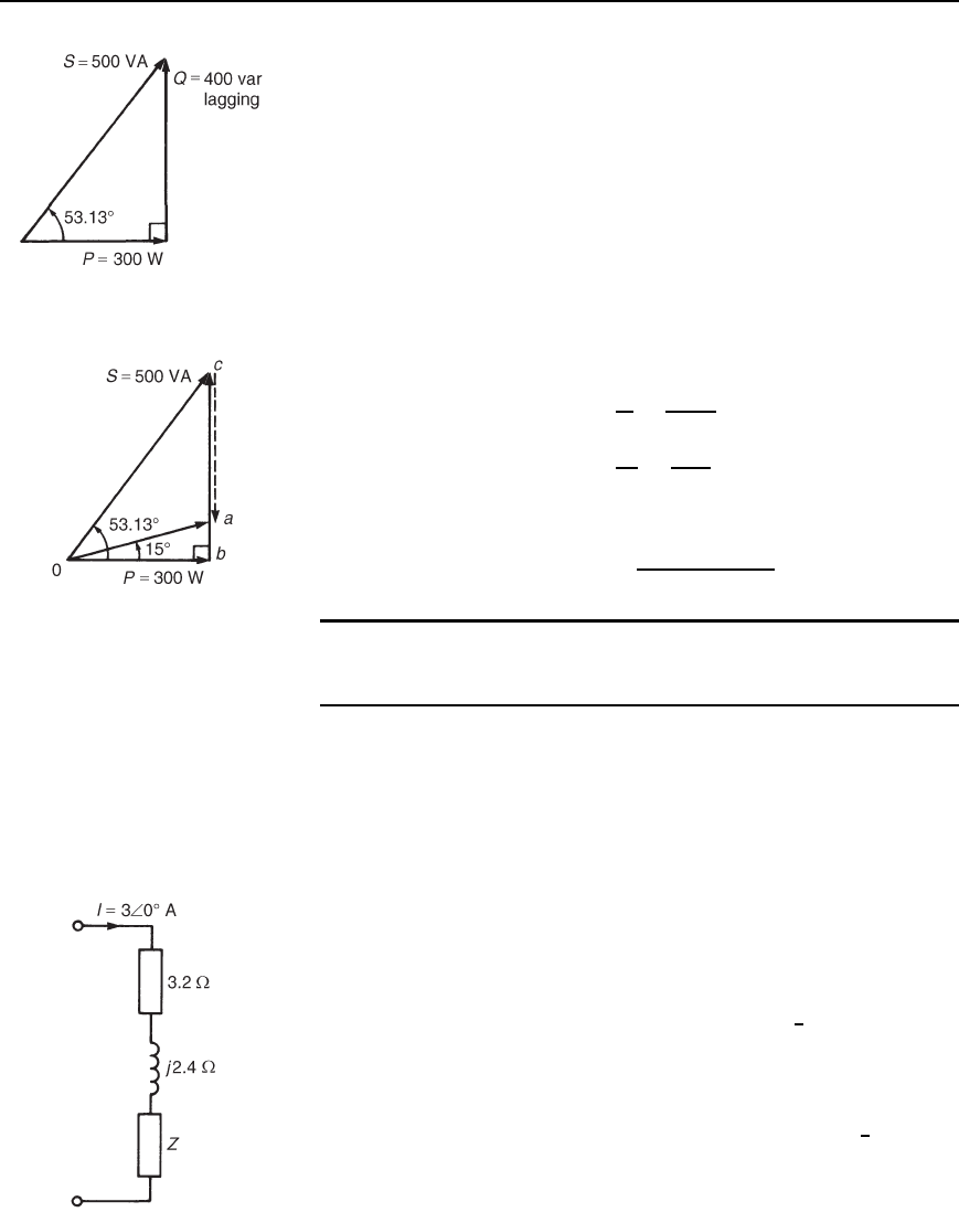
D 300 C j400VA D P C jQ
Hence active power, P
= 300 W
apparent power, S
= 500 VA and
reactive power, Q
= 400 var lagging.
472 Electrical Circuit Theory and Technology
Figure 26.14
The power triangle is shown in Figure 26.14.
(c) A power factor of 0.966 means that cos D 0.966.
Hence angle D arccos 0.966 D 15
°
To improve the power factor from cos 53.13
°
, i.e. 0.60, to 0.966, the
power triangle will need to change from Ocb (see Figure 26.15) to
0ab, the length ca representing the rating of a capacitor connected in
parallel with the circuit. From Figure 26.15, tan 15
°
D ab/300, from
which, ab D 300tan15
°
D 80.38 var.
Hence the rating of the capacitor,caD cb ab
D 400 80.38
D 319.6 var leading.
Figure 26.15
(d) Current in capacitor, I
C
D
Q
V
D
319.6
50
D 6.39 A
Capacitive reactance, X
C
D
V
I
C
D
50
6.39
D 7.82
Thus 7.82 D 1/2fC, from which,
required capacitance C D
1
215007.82
F 13.57 mF
Further problems on power factor improvement may be found in
Section 26.6 following, problems 13 to 16, page 473.
26.6 Further problems
on power in a.c. circuits
Power in a.c. circuits
1 When the voltage applied to a circuit is given by 2 C j5V, the
current flowing is given by 8 C j4A. Determine the power dissi-
pated in the circuit. [36 W]
2 A current of 12 C j5A flows in a circuit when the supply voltage
is 150 C j220V. Determine (a) the active power, (b) the reactive
power, and (c) the apparent power. Draw the power triangle.
[(a) 2.90 kW (b) 1.89 kvar lagging (c) 3.46 kVA]
3 A capacitor of capacitive reactance 40 and a resistance of 30
are connected in series to a supply voltage of 200
6
60
°
V. Determine
the active power in the circuit. [480 W]
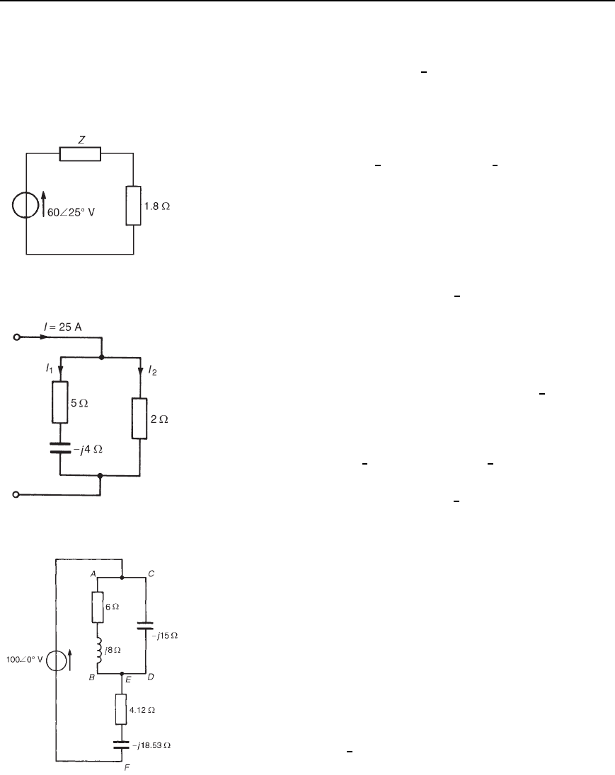
4 The circuit shown in Figure 26.16 takes 81 VA at a power factor of
0.8 lagging. Determine the value of impedance Z.
[4 C j3 or 5
6
36.87
°
]
5 A series circuit possesses inductance L and resistance R. The
circuit dissipates a power of 2.898 kW and has a power
factor of 0.966 lagging. If the applied voltage is given by
v D
169.7sin100t /4 volts, determine (a) the current flowing
Figure 26.16
Power in a.c. circuits 473
and its phase, (b) the value of resistance R, and (c) the value of
inductance L.
[(a) 25
6
60
°
A (b) 4.64 (c) 12.4 mH]
6 The p.d. across and the current in a certain circuit are represented
by 190 C j40Vand9 j4A respectively. Determine the active
power and the reactive power, stating whether the latter is leading
or lagging. [1550 W; 1120 var lagging]
7 Two impedances, Z
1
D 6
6
40
°
and Z
2
D 10
6
30
°
are connected
in series and have a total reactive power of 1650 var lagging. Deter-
mine (a) the average power, (b) the apparent power, and (c) the
power factor. [(a) 2469 W (b) 2970 VA (c) 0.83 lagging]
8 A current i D 7.5sinωt /4 A flows in a circuit which has
an applied voltage
v D 180sinωt C /12V. Determine (a) the
circuit impedance, (b) the active power, (c) the reactive power, and
(d) the apparent power. Draw the power triangle.
[(a) 24
6
60
°
(b) 337.5W
(c) 584.6 var lagging (d) 675 VA]
Figure 26.17
9 The circuit shown in Figure 26.17 has a power of 480 W and a power
factor of 0.8 leading. Determine (a) the apparent power, (b) the reac-
tive power, and (c) the value of impedance Z.
[(a) 600 VA (b) 360 var leading
(c) 3 j3.6 or 4.69
6
50.19
°
]
10 For the network shown in Figure 26.18, determine (a) the values of
currents I
1
and I
2
, (b) the total active power, (c) the reactive power,
and (d) the apparent power.
[(a) I
1
D 6.20
6
29.74
°
A,I
2
D 19.86
6
8.92
°
A (b) 981 W
(c) 153.9 var leading (d) 992.8VA]
Figure 26.18
11 A circuit consists of an impedance 5
6
45
°
in parallel with a
resistance of 10 . The supply current is 4 A. Determine for the
circuit (a) the active power, (b) the reactive power, and (c) the power
factor. [(a) 49.34 W (b) 28.90 var leading (c) 0.863 leading]
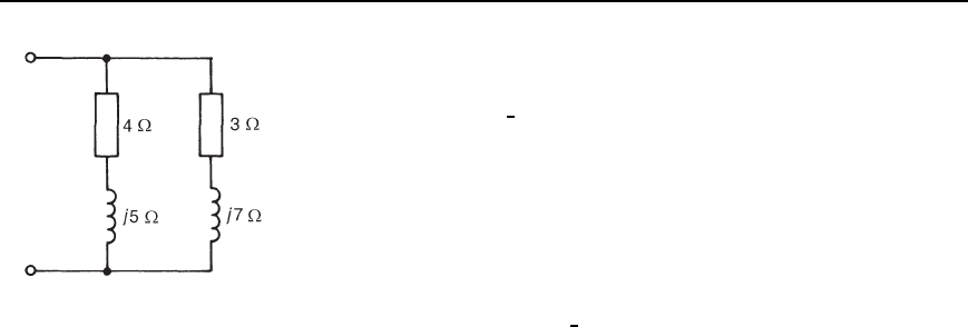
12 For the network shown in Figure 26.19, determine the active power
developed between points (a) A and B, (b) C and D, (c) E and F
[(a) 254.1 W (b) 0 (c) 65.92 W]
Power factor improvement
13 A 600 kVA transformer is at full load with an overall power factor of
0.64 lagging. The power factor is improved by adding capacitors in
parallel with the transformer until the overall power factor becomes
0.95 lagging. Determine the rating (in kvars) of the capacitors
needed. [334.8 kvar leading]
14 A source p.d. of 130
6
40
°
V at 2 kHz is applied to a circuit having an
impedance of 5 Cj12. Determine (a) the supply current, (b) the
active, apparent and reactive powers, (c) the rating of the capac-
itor to be connected in parallel with the impedance to improve the
Figure 26.19
474 Electrical Circuit Theory and Technology
Figure 26.20
power factor of the circuit to 0.940 lagging, and (d) the value of the
capacitance of the capacitor required.
[(a) 10
6
27.38
°
A (b) 500 W, 1300 VA, 1200 var lagging
(c) 1018.5 var leading (d) 4.797
µF]
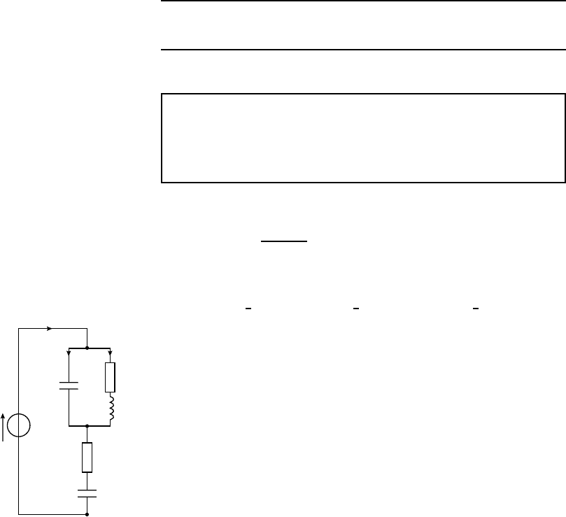
15 The network shown in Figure 26.20 has a total active power of
2253 W. Determine (a) the total impedance, (b) the supply current,
(c) the apparent power, (d) the reactive power, (e) the circuit power
factor, (f) the capacitance of the capacitor to be connected in parallel
with the network to improve the power factor to 0.90 lagging, if the
supply frequency is 50 Hz.
[(a) 3.51
6
58.40
°
(b) 35.0 A (c) 4300 VA
(d) 3662 var lagging (e) 0.524 lagging (f) 542.3
µF]
16 The power factor of a certain load is improved to 0.92 lagging with
the addition of a 30 kvar bank of capacitors. If the resulting supply
apparent power is 200 kVA, determine (a) the active power, (b) the
reactive power before power factor correction, and (c) the power
factor before correction.
[(a) 184 kW (b) 108.4 kvar lagging (c) 0.862 lagging]
Assignment 8
This assignment covers the material contained in chapters 23
to 26.
The marks for each question are shown in brackets at the end of
each question.
1 The total impedance Z
T
of an electrical circuit is given by:
Z
T
D Z
1
C
Z
2
ð Z
3
Z
2
C Z
3
Determine Z
T
in polar form, correct to 3 significant figures, when
Z
1
D 5.5
6
21
°
, Z
2
D 2.6
6
30
°
and Z
3
D 4.8
6
71
°
10
2 For the network shown in Figure A8.1, determine
(a) the equivalent impedance of the parallel branches
(b) the total circuit equivalent impedance
(c) current I
(d) the circuit phase angle
(e) currents I
1
and I
2
(f) the p.d. across points A and B
(g) the p.d. across points B and C
(h) the active power developed in the inductive branch
(i) the active power developed across the j10 capacitor
(j) the active power developed between points B and C
(k) the total active power developed in the network
(l) the total apparent power developed in the network
(m) the total reactive power developed in the network (30)
I
A
I
1
8 Ω
j6 Ω
B
5 Ω
−j3 Ω
C
170∠0° V
I
2
−j10 Ω
Figure A8.1
3 A 400 kVA transformer is at full load with an overall power factor
of 0.72 lagging. The power factor is improved by adding capaci-
tors in parallel with the transformer until the overall power factor
becomes 0.92 lagging. Determine the rating (in kilovars) of the capa-
citors required (10)
27 A.c. bridges
At the end of this chapter you should be able to:
ž derive the balance equations of any a.c. bridge circuit
ž state types of a.c. bridge circuit
ž calculate unknown components when using an a.c. bridge
circuit
27.1 Introduction
A.C. bridges are electrical networks, based upon an extension of
the Wheatstone bridge principle, used for the determination of an
unknown impedance by comparison with known impedances and for
the determination of frequency. In general, they contain four impe-
dance arms, an a.c. power supply and a balance detector which is sensitive
to alternating currents. It is more difficult to achieve balance in an
a.c. bridge than in a d.c. bridge because both the magnitude and the
phase angle of impedances are related to the balance condition. Balance
equations are derived by using complex numbers. A.C. bridges provide
precise methods of measurement of inductance and capacitance, as well
as resistance.
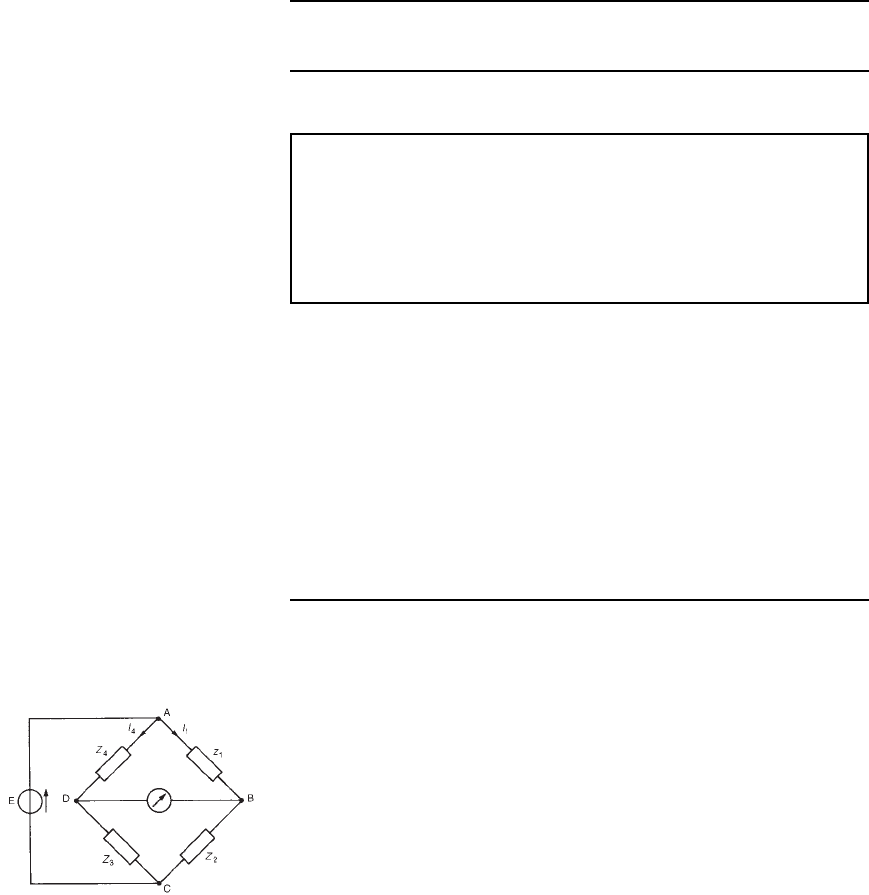
27.2 Balance conditions
for an a.c. bridge
The majority of well known a.c. bridges are classified as four-arm bridges
and consist of an arrangement of four impedances (in complex form,
Z D R š jX) as shown in Figure 27.1. As with the d.c. Wheatstone
bridge circuit, an a.c. bridge is said to be ‘balanced’ when the current
through the detector is zero (i.e., when no current flows between B and
D of Figure 27.1). If the current through the detector is zero, then the
current I
1
flowing in impedance Z
1
must also flow in impedance Z
2
.
Also, at balance, the current I
4
flowing in impedance Z
4
, must also flow
through Z
3
.
Figure 27.1 Four-arm bridge
At balance:
(i) the volt drop between A and B is equal to the volt drop between A
and D,
i.e., V
AB
D V
AD
i.e., I
1
Z
1
D I
4
Z
4
(both in magnitude and in phase) 27.1
(ii) the volt drop between B and C is equal to the volt drop between D
and C,
i.e., V
BC
D V
DC
A.c. bridges 477
i.e., I
1
Z
2
D I
4
Z
3
(both in magnitude and in phase) 27.2
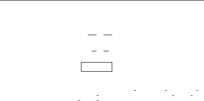
Dividing equation (27.1) by equation (27.2) gives
I
1
Z
1
I
1
Z
2
D
I
4
Z
4
I
4
Z
3
from which
Z
1
Z
2
D
Z
4
Z
3
or Z
1
Z
3
= Z
2
Z
4
27.3
Equation (27.3) shows that at balance the products of the impedances of
opposite arms of the bridge are equal.
If in polar form, Z
1
D
j
Z
1
j
6
˛
1
, Z
2
D
j
Z
2
j
6
˛
2
, Z
3
D
j
Z
3
j
6
˛
3
,
and Z
4
D
j
Z
4
j
6
˛
4
, then from equation (27.3),
j
Z
1
j
6
˛
1
j
Z
3
j
6
˛
3
D
j
Z
2
j
6
˛
2
j
Z
4
j
6
˛
4
, which shows that there are two conditions to be
satisfied simultaneously for balance in an a.c. bridge, i.e.,
j
Z
1
jj
Z
3
j
=
j
Z
2
jj
Z
4
j
and a
1
Y a
3
= a
2
Y a
4
When deriving balance equations of a.c. bridges, where at least two of
the impedances are in complex form, it is important to appreciate that for
a complex equation a C jb D c C jd the real parts are equal, i.e. a D c,
and the imaginary parts are equal, i.e., b D d.
Usually one arm of an a.c. bridge circuit contains the unknown
impedance while the other arms contain known fixed or variable
components. Normally only two components of the bridge are variable.
When balancing a bridge circuit, the current in the detector is gradually
reduced to zero by successive adjustments of the two variable components.
At balance, the unknown impedance can be expressed in terms of the fixed
and variable components.
Procedure for determining the balance equations of any a.c. bridge
circuit
(i) Determine for the bridge circuit the impedance in each arm in
complex form and write down the balance equation as in equa-
tion (27.3). Equations are usually easier to manipulate if L and C
are initially expressed as X
L
and X
C
, rather than ωL or 1/(ωC).
(ii) Isolate the unknown terms on the left-hand side of the equation in
the form a C jb.
(iii) Manipulate the terms on the right-hand side of the equation into
the form c C jd.
(iv) Equate the real parts of the equation, i.e., a D c, and equate the
imaginary parts of the equation, i.e., b D d.
(v) Substitute ωL for X
L
and 1/(ωC)forX
c
where appropriate and
express the final equations in their simplest form.
