Bird J. Electrical Circuit Theory and Technology
Подождите немного. Документ загружается.

448 Electrical Circuit Theory and Technology
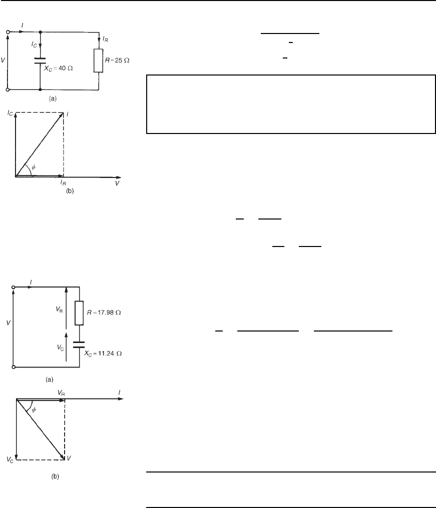
Figure 25.1 (a) Circuit
diagram, (b) Phasor diagram
Hence impedance Z D
1
0.0094
6
57.99
°
D 10.64
66
−57.99
°
Z or .5.64 − j9.02/Z
Problem 3. The admittance of a circuit is 0.040 C j0.025S.
Determine the values of the resistance and the capacitive reactance
of the circuit if they are connected (a) in parallel, (b) in series.
Draw the phasor diagram for each of the circuits.
(a) Parallel connection
Admittance Y D 0.040 C j0.025 S, therefore conductance, G D 0.040 S
and capacitive susceptance, B
C
D 0.025 S. From equation (25.1) when a
circuit consists of resistance R and capacitive reactance in parallel, then
Y D 1/R C j/X
C
.
Hence resistance R D
1
G
D
1
0.040
D 25 Z
and capacitive reactance X
C
D
1
B
C
D
1
0.025
D 40 Z
The circuit and phasor diagrams are shown in Figure 25.1.
(b) Series connection
Admittance Y D 0.040 Cj0.025 S, therefore
impedance Z D
1
Y
D
1
0.040 C j0.025
D
0.040 j0.025
0.040
2
C 0.025
2
D 17.98 j11.24
Thus the resistance, R
= 17.98 Z and capacitive reactance,
X
C
= 11.24 Z.
The circuit and phasor diagrams are shown in Figure 25.2.
The circuits shown in Figures 25.1(a) and 25.2(a) are equivalent in
that they take the same supply current I for a given supply voltage V; the
phase angle between the current and voltage is the same in each of the
phasor diagrams shown in Figures 25.1(b) and 25.2(b).
Further problems on admittance, conductance and susceptance may be
found in Section 25.4, problems 1 to 6, page 454.
Figure 25.2 (a) Circuit
diagram, (b) Phasor diagram
25.3 Parallel a.c.
networks
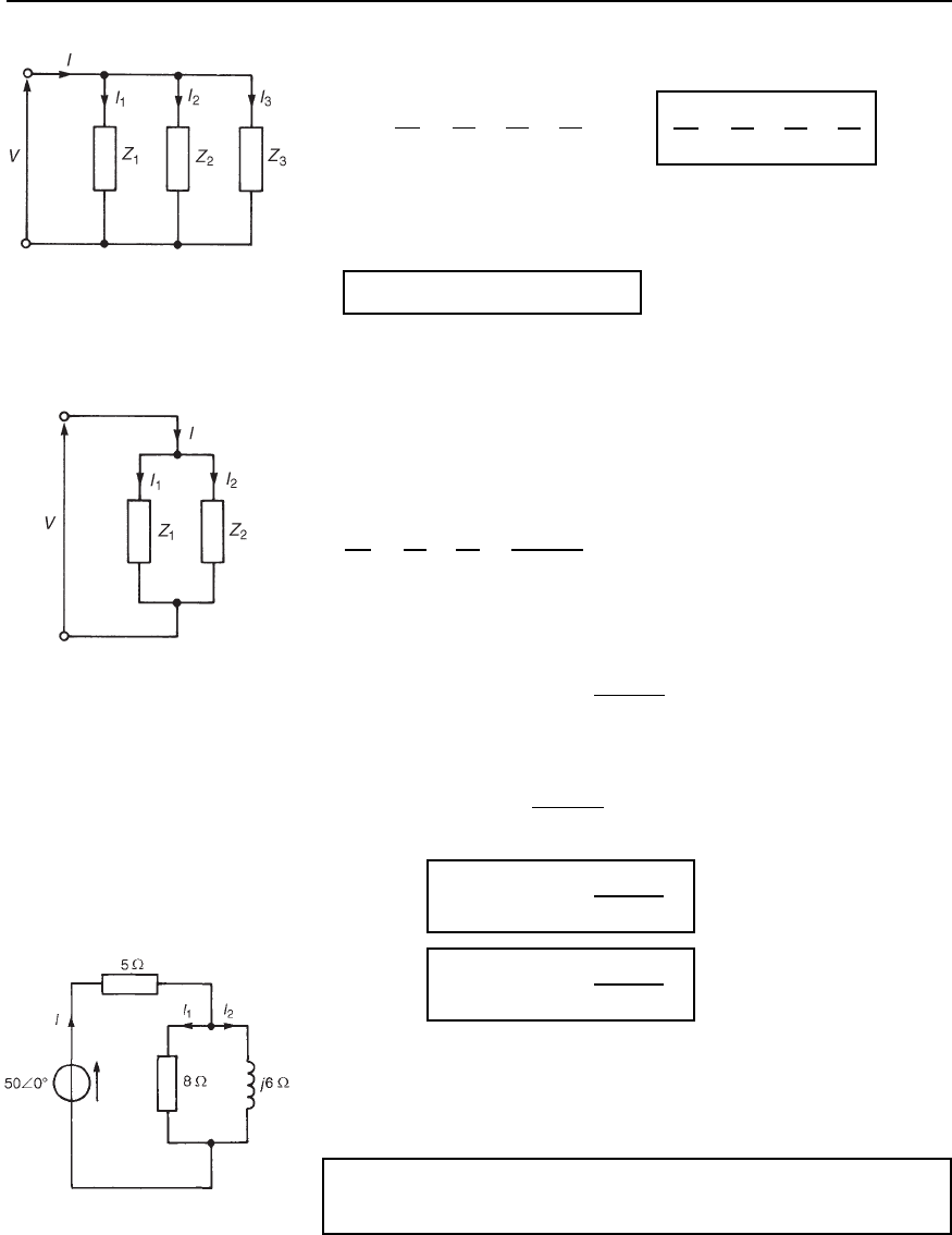
Figure 25.3 shows a circuit diagram containing three impedances, Z
1
,
Z
2
and Z
3
connected in parallel. The potential difference across each
impedance is the same, i.e. the supply voltage V. Current I
1
D V/Z
1
,
I
2
D V/Z
2
and I
3
D V/Z
3
.IfZ
T
is the total equivalent impedance of the
Application of complex numbers to parallel a.c. networks 449
Figure 25.3
circuit then I D V/Z
T
. The supply current, I D I
1
C I
2
C I
3
(phasorially).
Thus
V
Z
T
D
V
Z
1
C
V
Z
2
C
V
Z
3
and
1
Z
T
D
1
Z
1
C
1
Z
2
C
1
Z
3
or total admittance, Y
T
D Y
1
C Y
2
C Y
3
In general, for n impedances connected in parallel,
Y
T
= Y
1
Y Y
2
Y Y
3
Y ...Y Y
n
(phasorially)
It is in parallel circuit analysis that the use of admittance has its greatest
advantage.
Current division in a.c. circuits
For the special case of two impedances, Z
1
and Z
2
, connected in parallel
(see Figure 25.4),
1
Z
T
D
1
Z
1
C
1
Z
2
D
Z
2
C Z
1
Z
1
Z
2
The total impedance, Z
T
= Z
1
Z
2
=.Z
1
Y Z
2
/ (i.e. product/sum).
From Figure 25.4,
Figure 25.4
supply voltage, V D IZ
T
D I
Z
1
Z
2
Z
1
C Z
2
Also, V D I
1
Z
1
(and V D I
2
Z
2
)
Thus, I
1
Z
1
D I
Z
1
Z
2
Z
1
C Z
2
i.e., current I
1
= I
Z
2
Z
1
Y Z
2
Similarly, current I
2
= I
Z
1
Z
1
Y Z
2
Note that all of the above circuit symbols infer complex quantities either
in cartesian or polar form.
The following problems show how complex numbers are used to
analyse parallel a.c. networks.
Problem 4. Determine the values of currents I, I
1
and I
2
shown
in the network of Figure 25.5.
Figure 25.5
450 Electrical Circuit Theory and Technology
Total circuit impedance,
Z
T
D 5 C
8j6
8 C j6
D 5 C
j488 j6
8
2
C 6
2
D 5 C
j384 C 288
100
D 7.88 C j3.84 or 8.77
6
25.98
°
Current I D
V
Z
T
D
50
6
0
°
8.77
6
25.98
°
D 5.70
66
−25.98
°
A
Current I
1
D I
j6
8 C j6
D 5.70
6
25.98
°
6
6
90
°
10
6
36.87
°
D 3.42
66
27.15
°
A
Current I
2
D I
8
8 C j6
D 5.70
6
25.98
°
8
6
0
°
10
6
36.87
°
D 4.56
66
−62.85
°
A
[Note: I D I
1
C I
2
D 3.42
6
27.15
°
C 4.56
6
62.85
°
D 3.043 C j1.561 C 2.081 j4.058
D 5.124 j2.497 A D 5.70
6
25.98
°
A]
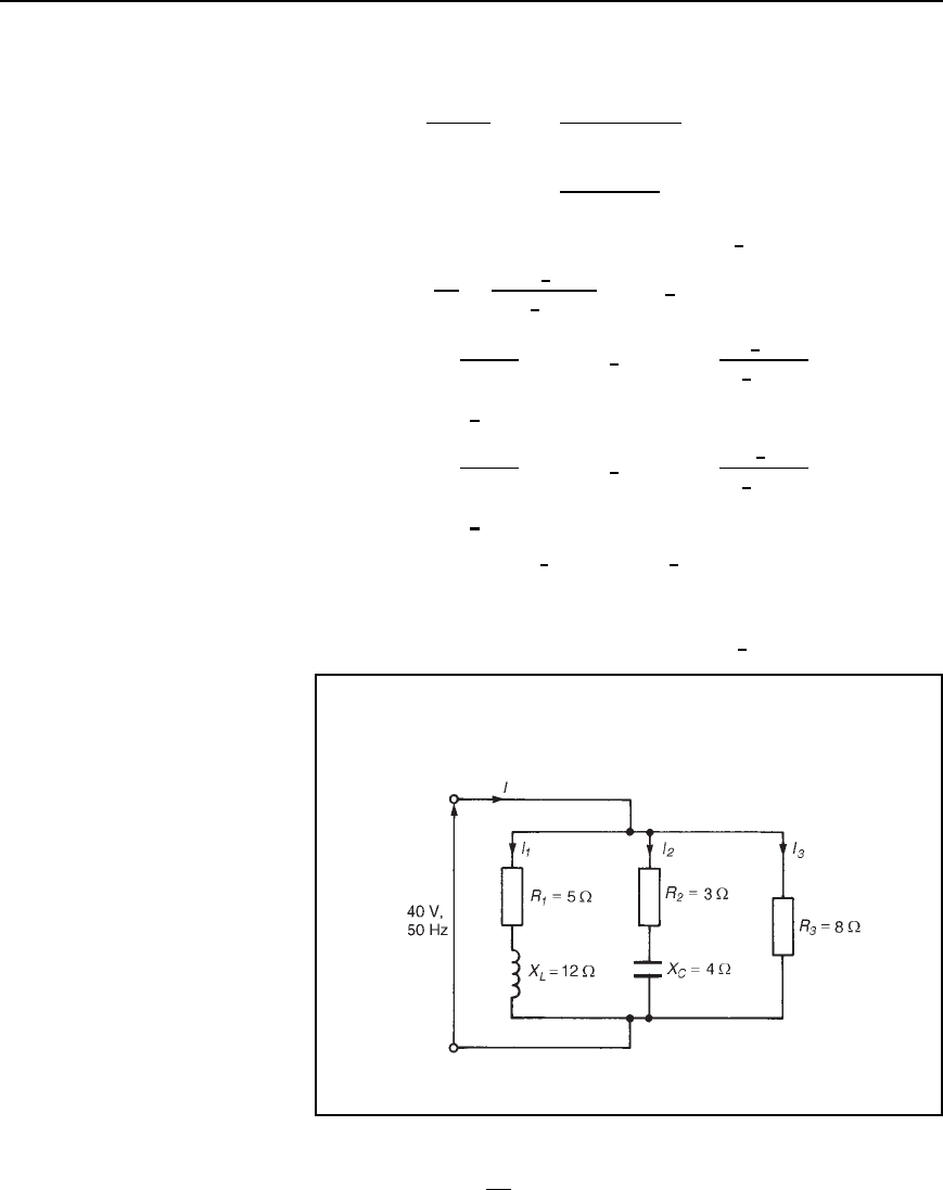
Problem 5. For the parallel network shown in Figure 25.6, deter-
mine the value of supply current I and its phase relative to the 40 V
supply.
Figure 25.6
Impedance Z
1
D 5 C j12, Z
2
D 3 j4 and Z
3
D 8
Supply current I D
V
Z
T
D VY
T
where Z
T
D total circuit impedance, and
Y
T
D total circuit admittance.
Application of complex numbers to parallel a.c. networks 451
Y
T
D Y
1
C Y
2
C Y
3
D
1
Z
1
C
1
Z
2
C
1
Z
3
D
1
5 C j12
C
1
3 j4
C
1
8
D
5 j12
5
2
C 12
2
C
3 C j4
3
2
C 4
2
C
1
8
D 0.0296 j0.0710 C 0.1200 C j0.1600 C 0.1250
i.e. Y
T
D 0.2746 C j0.0890Sor0.2887
6
17.96
°
S
Current I D VY
T
D 40
6
0
°
0.2887
6
17.96
°
D 11.55
6
17.96
°
A
Hence the current I is 11.55 A and is leading the 40 V supply by
17.96
°
Alternatively, current I D I
1
C I
2
C I
3
Current I
1
D
40
6
0
°
5 C j12
D
40
6
0
°
13
6
67.38
°
D 3.077
6
67.38
°
Aor1.183 j2.840 A
Current I
2
D
40
6
0
°
3 j4
D
40
6
0
°
5
6
53.13
°
D 8
6
53.13
°
Aor4.80 C j6.40 A
Current I
3
D
40
6
0
°
8
6
0
°
D 5
6
0
°
Aor5 C j0 A
Thus current I D I
1
C I
2
C I
3
D 1.183 j2.840 C 4.80 C j6.40 C 5 C j0
D 10.983 C j3.560 D 11.55
66
17.96
°
A, as previously
obtained.
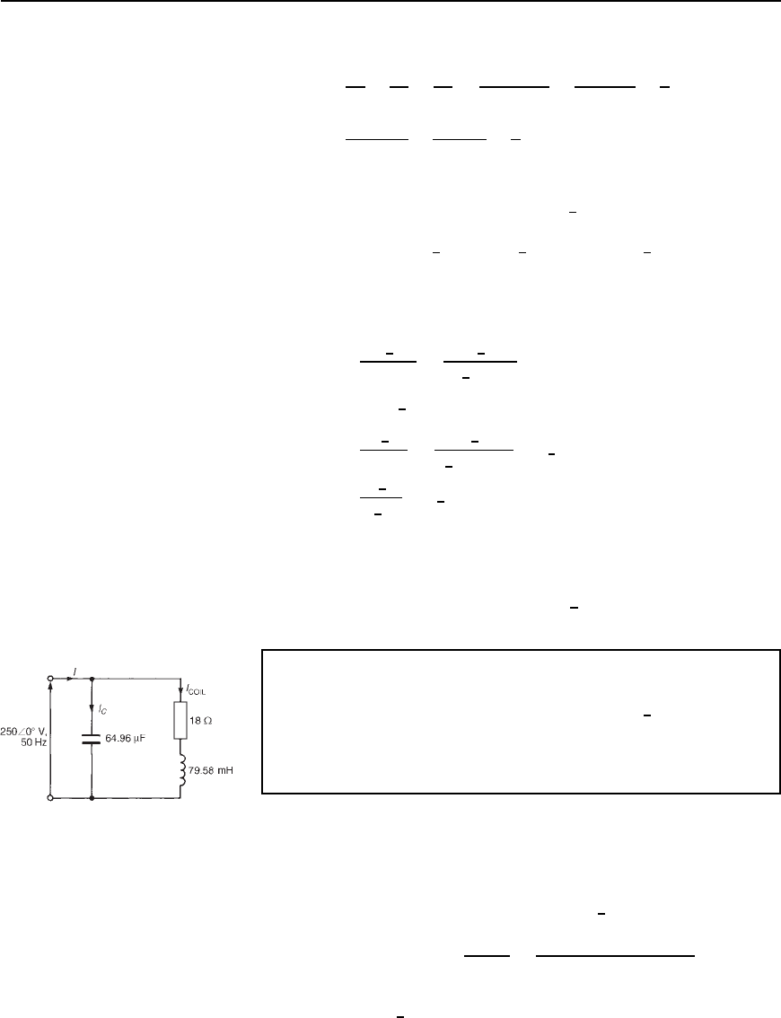
Problem 6. An a.c. network consists of a coil, of inductance
79.58 mH and resistance 18 , in parallel with a capacitor of
capacitance 64.96
µF. If the supply voltage is 250
6
0
°
Vat50Hz,
determine (a) the total equivalent circuit impedance, (b) the supply
current, (c) the circuit phase angle, (d) the current in the coil, and
(e) the current in the capacitor.
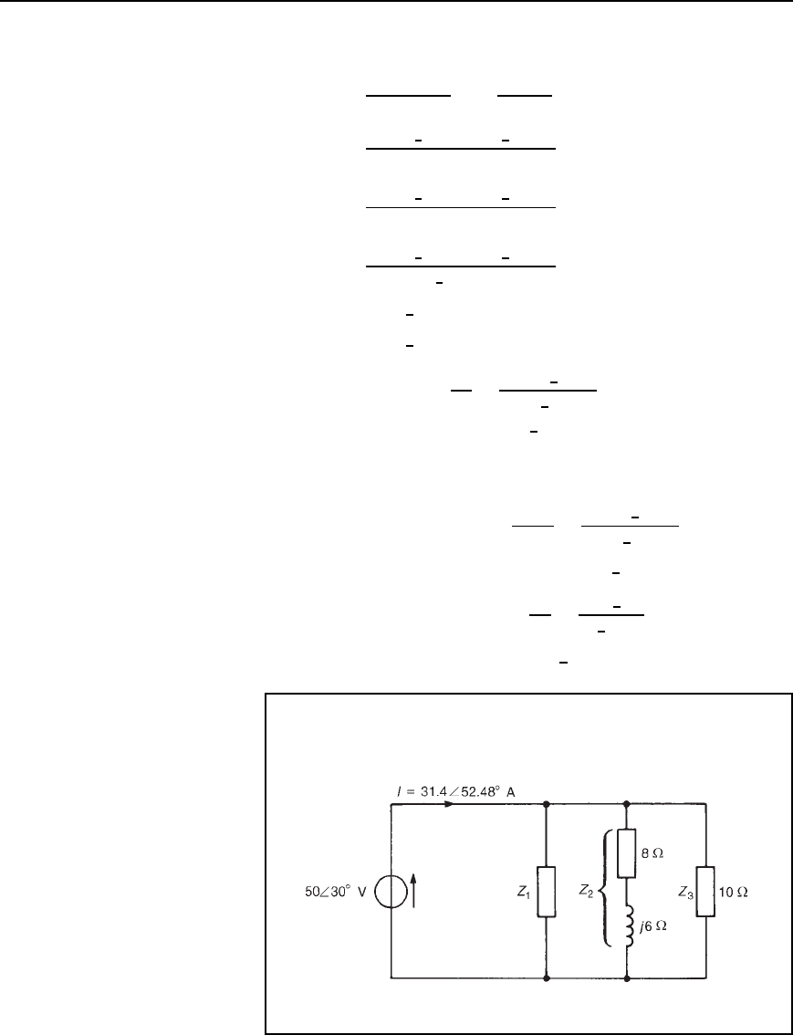
The circuit diagram is shown in Figure 25.7.
Figure 25.7
Inductive reactance, X
L
D 2fL D 25079.58 ð 10
3
D 25 .
Hence the impedance of the coil,
Z
COIL
D R C jX
L
D 18 C j25 or 30.81
6
54.25
°
Capacitive reactance, X
C
D
1
2fC
D
1
25064.96 ð 10
6
D 49
In complex form, the impedance presented by the capacitor, Z
C
is jX
C
,
i.e., j49 or 49
6
90
°
452 Electrical Circuit Theory and Technology
(a) Total equivalent circuit impedance,
Z
T
D
Z
COIL
X
C
Z
COIL
C Z
C
i.e.
product
sum
D
30.81
6
54.25
°
49
6
90
°
18 C j25 C j49
D
30.81
6
54.25
°
49
6
90
°
18 j24
D
30.81
6
54.25
°
49
6
90
°
30
6
53.13
°
D 50.32
6
54.25
°
90
°
53.13
°
D 50.32
66
17.38
°
Z or .48.02 Y j15.03/ Z
(b) Supply current I D
V
Z
T
D
250
6
0
°
50.32
6
17.38
°
D 4.97
66
−17.38
°
A
(c) Circuit phase angle D 17.38
°
lagging, i.e., the current I lags the vol-
tage V by 17.38
°
(d) Current in the coil, I
COIL
D
V
Z
COIL
D
250
6
0
°
30.81
6
54.25
°
D 8.11
66
−54.25
°
A
(e) Current in the capacitor, I
C
D
V
Z
C
D
250
6
0
°
49
6
90
°
D 5.10
66
90
°
A
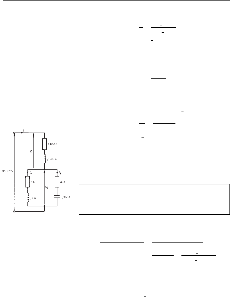
Problem 7. (a) For the network diagram of Figure 25.8, determine
the value of impedance Z
1
(b) If the supply frequency is 5 kHz,
determine the value of the components comprising impedance Z
1
Figure 25.8
Application of complex numbers to parallel a.c. networks 453
(a) Total circuit admittance,
Y
T
D
I
V
D
31.4
6
52.48
°
50
6
30
°
D 0.628
66
25.48
°
S or .0.58 Y j0.24/S
Y
T
D Y
1
C Y
2
C Y
3
Thus 0.58 Cj0.24 D Y
1
C
1
8 C j6
C
1
10
D Y
1
C
8 j6
8
2
C 6
2
C 0.1
i.e., 0.58 C j0.24 D Y
1
C 0.08 j0.06 C 0.1
Hence Y
1
D 0.58 0.08 0.1 C j0.24 Cj0.06
D 0.4 C j0.3Sor0.5
6
36.87
°
S
Thus impedance, Z
1
D
1
Y
1
D
1
0.5
6
36.87
°
D 2
66
−36.87
°
Z or .1.6 − j1.2/Z
(b) Since Z
1
D 1.6 j1.2, resistance = 1.6 Z and capacitive
reactance, X
C
D 1.2 .
Since X
C
D
1
2fC
, capacitance C D
1
2fX
C
D
1
250001.2
F
i.e., capacitance
= 26.53 mF
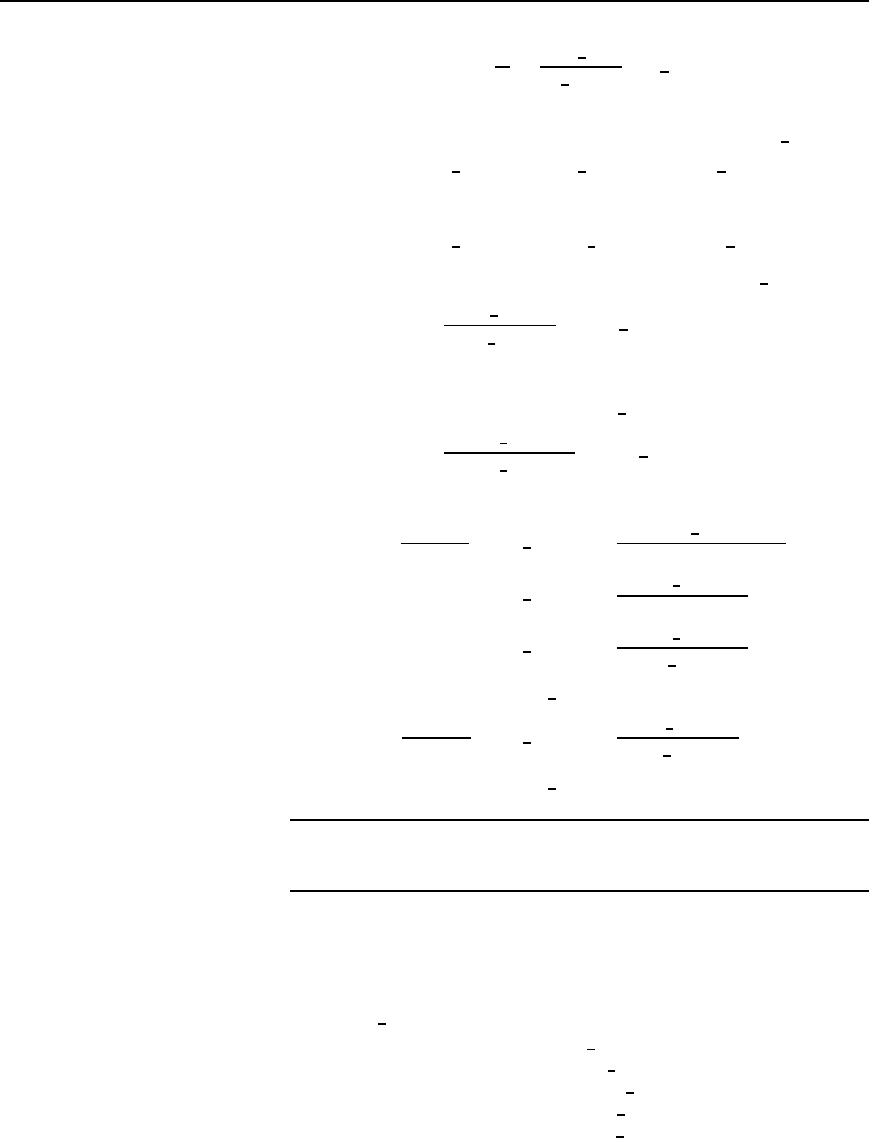
Problem 8. For the series-parallel arrangement shown in
Figure 25.9, determine (a) the equivalent series circuit impedance,
(b) the supply current I, (c) the circuit phase angle, (d) the values
of voltages V
1
and V
2
, and (e) the values of currents I
A
and I
B
Figure 25.9
(a) The impedance, Z, of the two branches connected in parallel is given
by:
Z D
5 C j74 j15
5 C j7 C 4 j15
D
20 j75 C j28 j
2
105
9 j8
D
125 j47
9 j8
D
133.54
6
20.61
°
12.04
6
41.63
°
D 11.09
6
21.02
°
or 10.35 Cj3.98
Equivalent series circuit impedance,
Z
T
D 1.65 C j1.02 C 10.35 C j3.98
= .12 Y j5/Z or 13
66
22.62
°
Z
454 Electrical Circuit Theory and Technology
(b) Supply current, I D
V
Z
D
91
6
0
°
13
6
22.62
°
D 7
66
−22.62
°
A
(c) Circuit phase angle D 22.62
°
lagging
(d) Voltage V
1
D IZ
1
, where Z
1
D 1.65 C j1.02 or 1.94
6
31.72
°
.
Hence V
1
D 7
6
22.62
°
1.94
6
31.72
°
D 13.58
66
9.10
°
V
Voltage V
2
D IZ, where Z is the equivalent impedance of the two
branches connected in parallel.
Hence V
2
D 7
6
22.62
°
11.09
6
21.02
°
D 77.63
66
−1.60
°
V
(e) Current I
A
D V
2
/Z
A
, where Z
A
D 5 C j7 or 8.60
6
54.46
°
.
Thus I
A
D
77.63
6
1.60
°
8.60
6
54.46
°
D 9.03
66
− 56.06
°
A
Current I
B
D V
2
/Z
B
,
where Z
B
D 4 j15 or 15.524
6
75.07
°
Thus I
B
D
77.63
6
1.60
°
15.524
6
75.07
°
D 5.00
66
73.47
°
A
[Alternatively, by current division,
I
A
D I
Z
B
Z
A
C Z
B
D 7
6
22.62
°
15.524
6
75.07
°
5 C j7 C 4 j15
D 7
6
22.62
°
15.524
6
75.07
°
9 j8
D 7
6
22.62
°
15.524
6
75.07
°
12.04
6
41.63
°
D 9.03
66
−56.06
°
A
I
B
D I
Z
A
Z
A
C Z
B
D 7
6
22.62
°
8.60
6
54.46
°
12.04
6
41.63
°
D 5.00
66
73.47
°
A]
Further problems on parallel a.c. networks may be found in Section 25.4
following, problems 7 to 21, page 455.
25.4 Further problems
on parallel a.c. networks
Admittance, conductance and susceptance
1 Determine the admittance (in polar form), conductance and suscep-
tance of the following impedances: (a) j10 (b) j40
(c) 32
6
30
°
(d) 5 C j9 (e) 16 j10
[(a) 0.1
6
90
°
S, 0, 0.1S
(b) 0.025
6
90
°
S, 0, 0.025 S
(c) 0.03125
6
30
°
S, 0.0271 S, 0.0156 S
(d) 0.0971
6
60.95
°
S, 0.0472 S, 0.0849 S
(e) 0.0530
6
32.01
°
S, 0.0449 S, 0.0281 S]
Application of complex numbers to parallel a.c. networks 455
Figure 25.10
2 Derive expressions, in polar form, for the impedances of the
following admittances: (a) 0.05
6
40
°
S (b) 0.0016
6
25
°
S (c) 0.1 C
j0.4S(d)0.025 j0.040S
[(a) 20
6
40
°
(b) 625
6
25
°
(c) 2.425
6
75.96
°
(d) 21.20
6
57.99
°
]
3 The admittance of a series circuit is 0.010 j0.004S. Determine
the values of the circuit components if the frequency is 50 Hz.
[R D 86.21 , L D 109.8mH]
4 The admittance of a network is 0.05 j0.08S. Determine the
values of resistance and reactance in the circuit if they are connected
(a) in series, (b) in parallel.
[(a) R D 5.62 , X
L
D 8.99 (b) R D 20 , X
L
D 12.5 ]
5 The admittance of a two-branch parallel network is 0.02 C j0.05S.
Determine the circuit components if the frequency is 1 kHz.
[R D 50 , C D 7.958
µF]
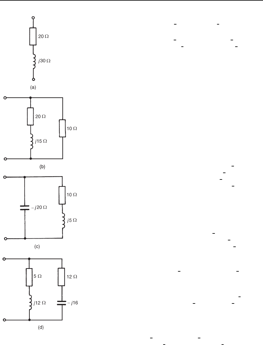
6 Determine the total admittance, in rectangular and polar forms, of
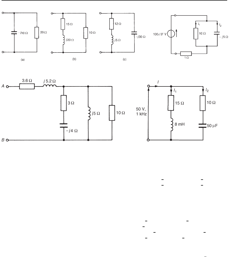
each of the networks shown in Figure 25.10.
[(a) 0.0154 j0.0231Sor0.0278
6
56.31
°
S
(b) 0.132 j0.024Sor0.134
6
10.30
°
S
(c) 0.08 Cj0.01Sor0.0806
6
7.125
°
S
(d) 0.0596 j0.0310Sor0.0672
6
27.48
°
S]
Parallel a.c. networks
7 Determine the equivalent circuit impedances of the parallel networks
shown in Figure 25.11.
[(a) 4 j8 or 8.94
6
63.43
°
(b) 7.56 Cj1.95 or 7.81
6
14.46
°
(c) 14.04 j0.74 or 14.06
6
3.02
°
]
8 Determine the value and phase of currents I
1
and I
2
in the network
shown in Figure 25.12.
[I
1
D 8.94
6
10.30
°
A,I
2
D 17.89
6
79.70
°
A]
9 For the series-parallel network shown in Figure 25.13, determine
(a) the total network impedance across AB, and (b) the supply
current flowing if a supply of alternating voltage 30
6
20
°
Vis
connected across AB. [(a) 10
6
36.87
°
(b) 3
6
16.87
°
A]
10 For the parallel network shown in Figure 25.14, determine (a) the
equivalent circuit impedance, (b) the supply current I, (c) the circuit
phase angle, and (d) currents I
1
and I
2
[(a) 10.33
6
6.31
°
(b) 4.84
6
6.31
°
A (c) 6.31
°
leading
(d) I
1
D 0.953
6
73.38
°
A,I
2
D 4.765
6
17.66
°
A]
456 Electrical Circuit Theory and Technology
Figure 25.11 Figure 25.12
Figure 25.13 Figure 25.14
11 For the network shown in Figure 25.15, determine (a) current I
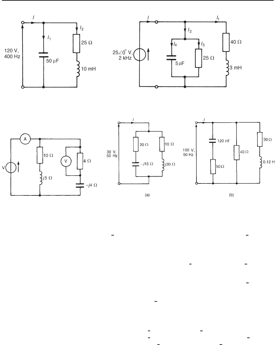
1
,
(b) current I
2
, (c) current I, (d) the equivalent input impedance, and
(e) the supply phase angle.
[(a) 15.08
6
90
°
A (b) 3.39
6
45.15
°
A
(c) 12.90
6
79.33
°
A (d) 9.30
6
79.33
°
(e) 79.33
°
leading]
12 Determine, for the network shown in Figure 25.16, (a) the total
network admittance, (b) the total network impedance, (c) the supply
current I, (d) the network phase angle, and (e) currents I
1
, I
2
, I
3
and I
4
[(a) 0.0733
6
43.39
°
S (b) 13.64
6
43.39
°
(c) 1.833
6
43.39
°
A (d) 43.39
°
leading
(e) I
1
D 0.455
6
43.30
°
A,I
2
D 1.863
6
57.50
°
A,
I
3
D 1
6
0
°
A,I
4
D 1.570
6
90
°
A]
13 Four impedances of 10 j20, 30 C j0, 2 j15 and
25 C j12 are connected in parallel across a 250 V ac. supply.
Find the supply current and its phase angle. [32.62
6
43.55
°
A]
14 In the network shown in Figure 25.17, the voltmeter indicates 24 V.
Determine the reading on the ammeter. [7.53 A]
15 Three impedances are connected in parallel to a 100 V, 50 Hz supply.
The first impedance is 10 C j12.5 and the second impedance is
Application of complex numbers to parallel a.c. networks 457
Figure 25.15 Figure 25.16
Figure 25.17 Figure 25.18
20 C j8. Determine the third impedance if the total current is
20
6
25
°
A[9.74 C j1.82 or 9.91
6
10.56
°
]
16 For each of the network diagrams shown in Figure 25.18, determine
the supply current I and their phase relative to the applied voltages.
[(a) 1.632
6
17.10
°
A (b) 5.411
6
8.46
°
A]
17 Determine the value of current flowing in the 12 C j9 impedance
in the network shown in Figure 25.19. [7.66
6
33.63
°
A]
18 In the series-parallel network shown in Figure 25.20 the p.d. between
points A and B is 50
6
68.13
°
V. Determine (a) the supply current I,
(b) the equivalent input impedance, (c) the supply voltage V, (d) the
supply phase angle, (e) the p.d. across points B and C, and (f) the
value of currents I
1
and I
2
[(a) 11.99
6
31.81
°
A (b) 8.54
6
20.56
°
(c) 102.4
6
11.25
°
V (d) 20.56
°
lagging (e) 86.0
6
17.91
°
V
(f) I
1
D 7.37
6
13.05
°
A I
2
D 5.54
6
57.16
°
A]
