Bird J. Electrical Circuit Theory and Technology
Подождите немного. Документ загружается.

458 Electrical Circuit Theory and Technology
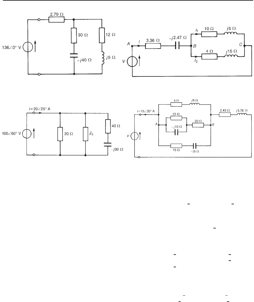
Figure 25.19 Figure 25.20
Figure 25.21 Figure 25.22
19 For the network shown in Figure 25.21, determine (a) the value of
impedance Z
2
, (b) the current flowing in Z
2
, and (c) the components
comprising Z
2
if the supply frequency is 2 kHz
[(a) 6.25
6
52.34
°
(b) 16.0
6
7.66
°
A
(c) R D 3.819 , L D 0.394 mH]
20 Coils of impedance 5 C j8 and 12 Cj16 are connected
in parallel. In series with this combination is an impedance of
15 j40. If the alternating supply pd. is 150
6
0
°
V, determine
(a) the equivalent network impedance, (b) the supply current, (c) the
supply phase angle, (d) the current in the 5 C j8 impedance, and
(e) the current in the 12 Cj16 impedance.
[(a) 39.31
6
61.84
°
(b) 3.816
6
61.84
°
A
(c) 61.84
°
leading (d) 2.595
6
60.28
°
A
(e) 1.224
6
65.15
°
A]
21 For circuit shown in Figure 25.22, determine (a) the input
impedance, (b) the source voltage V, (c) the p.d. between points A
and B, and (d) the current in the 10 resistor.
[(a) 10.0
6
36.87
°
(b) 150
6
66.87
°
V
(c) 90
6
51.92
°
V (d) 2.50
6
18.23
°
A]

26 Power in a.c. circuits
At the end of this chapter you should be able to:
ž determine active, apparent and reactive power in a.c.
series/parallel networks
ž appreciate the need for power factor improvement
ž perform calculations involving power factor improvement
26.1 Introduction
Alternating currents and voltages change their polarity during each cycle.
It is not surprising therefore to find that power also pulsates with time.
The product of voltage
v and current i at any instant of time is called
instantaneous power p, and is given by:
p
= vi
26.2 Determination of
power in a.c. circuits
(a) Purely resistive a.c. circuits
Let a voltage
v D V
m
sinωt be applied to a circuit comprising resistance
only. The resulting current is i D I
m
sinωt, and the corresponding instan-
taneous power, p, is given by:
p D
vi D V
m
sinωtI
m
sinωt
i.e., p D V
m
I
m
sin
2
ωt
From trigonometrical double angle formulae, cos2A D 1 2sin
2
A, from
which,
sin
2
A D
1
2
1 cos2A
Thus sin
2
ωt D
1
2
1 cos2ωt
Then power p D V
m
I
m
1
2
1 cos2ωt
, i.e., p =
1
2
V
m
I
m
.1 − cos2!t/.
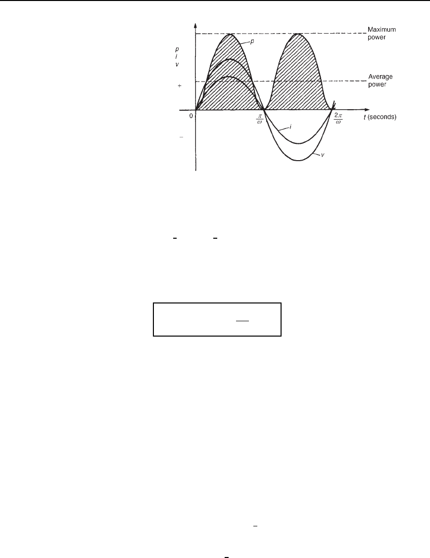
The waveforms of
v, i and p are shown in Figure 26.1. The waveform
of power repeats itself after /ω seconds and hence the power has a
frequency twice that of voltage and current. The power is always positive,
having a maximum value of V
m
I
m
. The average or mean value of the
power is
1
2
V
m
I
m
.
The rms value of voltage V D 0.707 V
m
,i.e.V D V
m
/
p
2, from which,
V
m
D
p
2 V. Similarly, the rms value of current, I D I
m
/
p
2, from which,
I
m
D
p
2 I. Hence the average power, P, developed in a purely resistive
460 Electrical Circuit Theory and Technology
Figure 26.1 The waveforms of v, i and p
a.c. circuit is given by
P D
1
2
V
m
I
m
D
1
2
p
2 V
p
2 I D VI watts
Also, power P D I
2
R or V
2
/R as for a d.c. circuit, since V D IR.
Summarizing, the average power P in a purely resistive a.c. circuit is
given by
P = VI = I
2
R =
V
2
R
watts
where V and I are rms values.
(b) Purely inductive a.c. circuits
Let a voltage
v D V
m
sinωt be applied to a circuit containing pure induc-
tance (theoretical case). The resulting current is i D I
m
sinωt /2
since current lags voltage by 90
°
in a purely inductive circuit, and the
corresponding instantaneous power, p, is given by:
p D
vi D V
m
sinωtI
m
sinωt /2
i.e., p D V
m
I
m
sinωt sinωt /2
However, sinωt /2 Dcosωt
Thus p DV
m
I
m
sinωt cosωt
Rearranging gives: p D
1
2
V
m
I
m
2 sin ωt cosωt. However, from the
double-angle formulae, 2sinωt cosωt D sin 2ωt.
Thus power, p
= −
1
2
V
m
I
m
sin2!t
Power in a.c. circuits 461
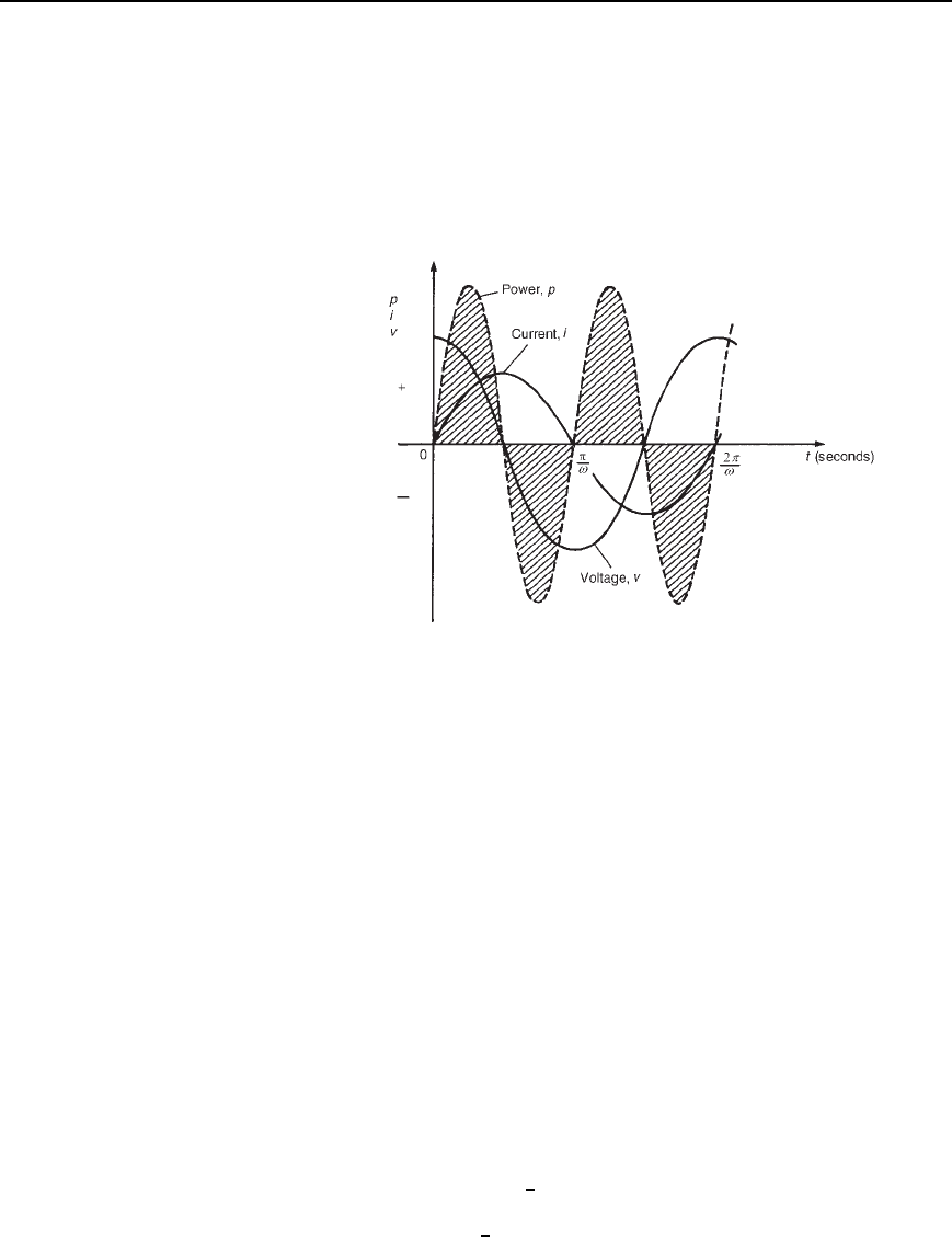
The waveforms of v, i and p are shown in Figure 26.2. The frequency of
power is twice that of voltage and current. For the power curve shown
in Figure 26.2, the area above the horizontal axis is equal to the area
below, thus over a complete cycle the average power P is zero. It is
noted that when
v and i are both positive, power p is positive and energy
is delivered from the source to the inductance; when
v and i have opposite
signs, power p is negative and energy is returned from the inductance to
the source.
Figure 26.2 Power in a purely inductive a.c. circuit
In general, when the current through an inductance is increasing, energy
is transferred from the circuit to the magnetic field, but this energy is
returned when the current is decreasing.
Summarizing, the average power P in a purely inductive a.c. circuit
is zero.
(c) Purely capacitive a.c. circuits
Let a voltage
v D V
m
sinωt be applied to a circuit containing pure capac-
itance. The resulting current is i D I
m
sinωt C /2, since current leads
voltage by 90
°
in a purely capacitive circuit, and the corresponding instan-
taneous power, p, is given by:
p D
vi D V
m
sinωtI
m
sinωt C /2
i.e., p D V
m
I
m
sinωt sinωt C /2
However, sinωt C /2 D cosωt.
Thus P D V
m
I
m
sinωt cosωt
Rearranging gives p D
1
2
V
m
I
m
2 sin ωt cosωt.
Thus power, p
=
1
2
V
m
I
m
sin2!t
462 Electrical Circuit Theory and Technology
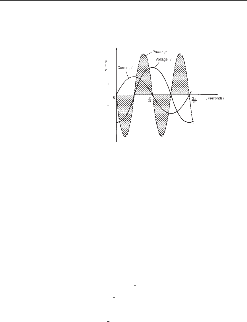
The waveforms of v, i and p are shown in Figure 26.3. Over a complete
cycle the average power P is zero. When the voltage across a capacitor
is increasing, energy is transferred from the circuit to the electric field,
but this energy is returned when the voltage is decreasing.
Figure 26.3 Power in a purely capacitive a.c. circuit
Summarizing, the average power P in a purely capacitive a.c. circuit
is zero.
(d) R–L or R–C a.c. circuits
Let a voltage
v D V
m
sinωt be applied to a circuit containing resistance
and inductance or resistance and capacitance. Let the resulting current
be i D I
m
sinωt C , where phase angle will be positive for an R–C
circuit and negative for an R –L circuit. The corresponding instantaneous
power, p, is given by:
p D
vi D V
m
sinωtI
m
sinωt C
i.e., p D V
m
I
m
sinωt sinωt C
Products of sine functions may be changed into differences of cosine
functions by using: sinA sinB D
1
2
[cosA C B cosA B]
Substituting ωt D A and ωt C D B gives:
power, p D V
m
I
m
1
2
[cosωt C ωt C cosωt ωt C ]
i.e., p D
1
2
V
m
I
m
[cos cos2ωt C ]
However, cos D cos.
Thus p
=
1
2
V
m
I
m
[cosf − cos.2!t Y f/]
Power in a.c. circuits 463
The instantaneous power p thus consists of
(i) a sinusoidal term,
1
2
V
m
I
m
cos2ωt C , which has a mean value
over a cycle of zero, and
(ii) a constant term,
1
2
V
m
I
m
cos (since is constant for a particular
circuit).
Thus the average value of power, P D
1
2
V
m
I
m
cos.
Since V
m
D
p
2 V and I
m
D
p
2 I,
average power, P D
1
2
p
2 V
p
2 I cos
i.e.,
P = VI cosf watts
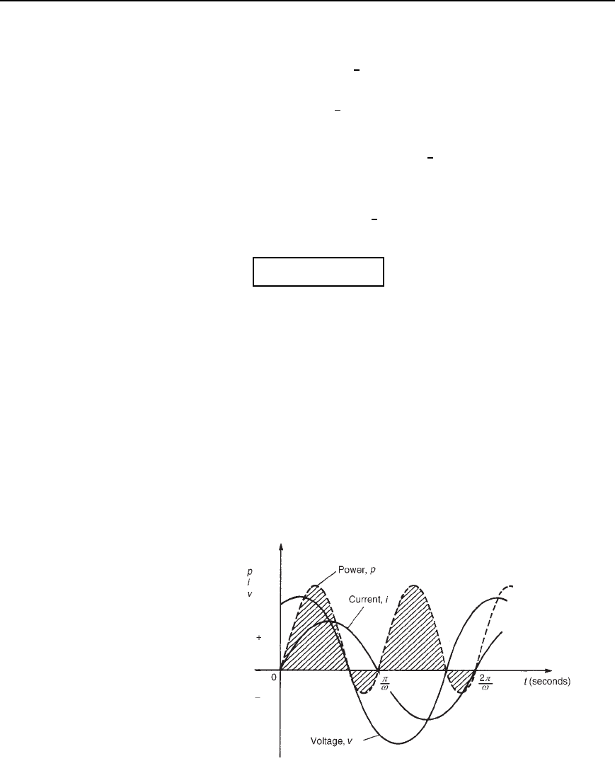
The waveforms of v, i and p, are shown in Figure 26.4 for an R–L circuit.
The waveform of power is seen to pulsate at twice the supply frequency.
The areas of the power curve (shown shaded) above the horizontal time
axis represent power supplied to the load; the small areas below the axis
represent power being returned to the supply from the inductance as the
magnetic field collapses.
A similar shape of power curve is obtained for an R –C circuit, the
small areas below the horizontal axis representing power being returned
to the supply from the charged capacitor. The difference between the areas
above and below the horizontal axis represents the heat loss due to the
circuit resistance. Since power is dissipated only in a pure resistance, the
alternative equations for power, P D I
2
R
R, may be used, where I
R
is the
rms current flowing through the resistance.
Figure 26.4 Power in a.c. circuit containing resistance and inductive
reactance
464 Electrical Circuit Theory and Technology
Summarizing, the average power P in a circuit containing resistance
and inductance and/or capacitance, whether in series or in parallel,
is given by P
= VI cosf or P = I
2
R
R .V ,I and I
R
being rms values).
26.3 Power triangle and
power factor
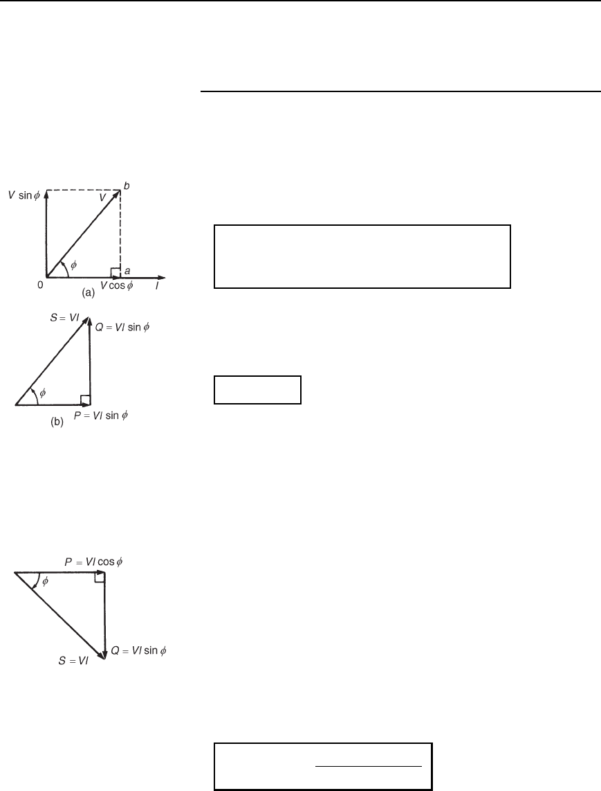
A phasor diagram in which the current I lags the applied voltage V
by angle (i.e., an inductive circuit) is shown in Figure 26.5(a). The
horizontal component of V is V cos, and the vertical component of V is
V sin. If each of the voltage phasors of triangle Oab is multiplied by I,
Figure 26.5(b) is produced and is known as the ‘power triangle’. Each
side of the triangle represents a particular type of power:
True or active power P= VI cosf watts (W)
Apparent power S
= VI voltamperes (VA)
Reactive power Q
= VI sinf vars (var)
The power triangle is not a phasor diagram since quantities P, Q and S
are mean values and not rms values of sinusoidally varying quantities.
Superimposing the power triangle on an Argand diagram produces a
relationship between P, S and Q in complex form, i.e.,
S = P Y jQ
Figure 26.5 (a) Phasor
diagram, (b) Power triangle for
inductive circuit
Apparent power, S, is an important quantity since a.c. apparatus, such
as generators, transformers and cables, is usually rated in voltamperes
rather than in watts. The allowable output of such apparatus is usually
limited not by mechanical stress but by temperature rise, and hence by
the losses in the device. The losses are determined by the voltage and
current and are almost independent of the power factor. Thus the amount
of electrical equipment installed to supply a certain load is essentially
determined by the voltamperes of the load rather than by the power alone.
The rating of a machine is defined as the maximum apparent power that
it is designed to carry continuously without overheating.
The reactive power, Q, contributes nothing to the net energy transfer
and yet it causes just as much loading of the equipment as if it did so.
Reactive power is a term much used in power generation, distribution and
utilization of electrical energy.
Inductive reactive power, by convention, is defined as positive reactive
power; capacitive reactive power, by convention, is defined as negative
reactive power. The above relationships derived from the phasor diagram
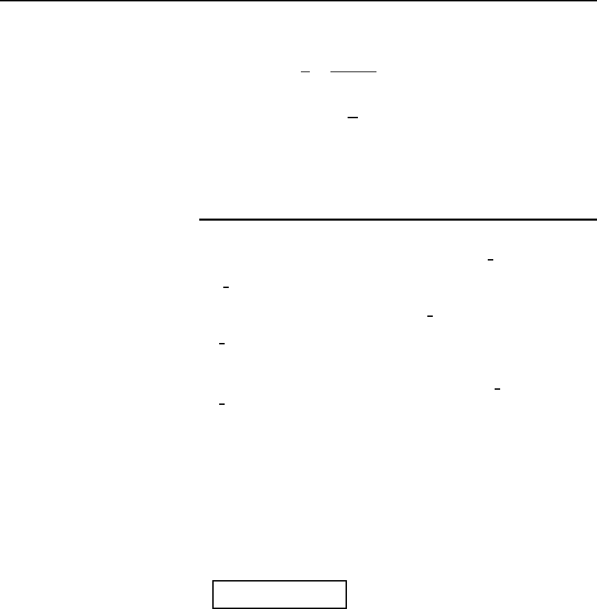
of an inductive circuit may be shown to be true for a capacitive circuit,
the power triangle being as shown in Figure 26.6.
Figure 26.6 Power triangle for
capacitive circuit
Power factor is defined as:
power factor =
active power P
apparent power S
Power in a.c. circuits 465
For sinusoidal voltages and currents,
power factor D
P
S
D
VI cos
VI
D cosf
=
R
Z
(from the impedance triangle)
A circuit in which current lags voltage (i.e., an inductive circuit) is said
to have a lagging power factor, and indicates a lagging reactive power Q.
A circuit in which current leads voltage (i.e., a capacitive circuit) is said
to have a leading power factor, and indicates a leading reactive power Q.
26.4 Use of complex
numbers for
determination of power
Let a circuit be supplied by an alternating voltage V
6
˛, where
V
6
˛ D Vcos˛ C j sin˛ D V cos˛ C jV sin ˛ D a C jb 26.1
Let the current flowing in the circuit be I
6
ˇ, where
I
6
ˇ D Icos ˇ C j sin ˇ D I cos ˇ C jIsin ˇ D c C jd 26.2
From Sections 26.2 and 26.3, power P D VI cos , where is the angle
between the voltage V and current I. If the voltage is V
6
˛
°
and the current
is I
6
ˇ
°
, then the angle between voltage and current is ˛ ˇ
°
Thus power, P D VI cos˛ ˇ
From compound angle formulae, cos˛ ˇ D cos˛ cosˇ C sin˛ sinˇ.
Hence power, P D VI[cos ˛ cos ˇ C sin ˛ sin ˇ]
Rearranging gives P D V cos ˛I cos ˇ C V sin˛I sinˇ, i.e.,
P D ac C bd from equations (26.1) and (26.2)
Summarizing, if V
= .a Y jb/ and I = .c Y jd/, then
power, P = ac Y bd
26.3
Thus power may be calculated from the sum of the products of the real
components and imaginary components of voltage and current.
Reactive power, Q D VI sin˛ ˇ
From compound angle formulae, sin˛ ˇ D sin˛ cosˇ cos˛ sinˇ.
Thus Q D VI[sin˛ cos ˇ cos˛ sin ˇ]
Rearranging gives Q D V sin ˛I cosˇ V cos ˛I sin ˇ i.e.,
Q D bc ad from equations (26.1) and (26.2).
466 Electrical Circuit Theory and Technology
Summarizing, if V = .a Y jb/ and I = .c Y jd/, then
reactive power,
Q = bc − ad 26.4
Expressions (26.3) and (26.4) provide an alternative method of deter-
mining true power P and reactive power Q when the voltage and current
are complex quantities. From Section 26.3, apparent power S D P C jQ.
However, merely multiplying V by I in complex form will not give this
result, i.e. (from above)
S D VI D a C jbc C jd D ac bd C jbc C ad
Here the real part is not the expression for power as given in equa-
tion (26.3) and the imaginary part is not the expression of reactive power
given in equation (26.4)
The correct expression may be derived by multiplying the voltage V
by the conjugate of the current, i.e. c jd, denoted by I
Ł
. Thus
apparent power S
= VI
∗
D a C jbc jd
D ac C bd C jbc ad
i.e.,
S = P Y jQ
, from equations (26.3) and (26.4).
Thus the active and reactive powers may be determined if, and only
if, the voltage V is multiplied by the conjugate of current I. As stated
in Section 26.3, a positive value of Q indicates an inductive circuit, i.e.,
a circuit having a lagging power factor, whereas a negative value of
Q indicates a capacitive circuit, i.e., a circuit having a leading power
factor.
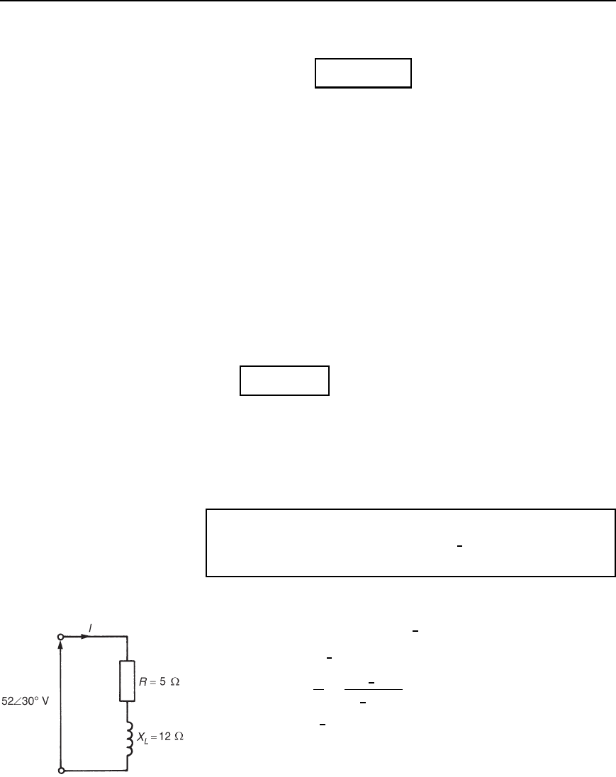
Problem 1. A coil of resistance 5 and inductive reactance 12
is connected across a supply voltage of 52
6
30
°
volts. Determine the
active power in the circuit.
The circuit diagram is shown in Figure 26.7.
Impedance Z D 5 C j12 or 13
6
67.38
°
Voltage V D 52
6
30
°
Vor45.03 C j26.0V
Current I D
V
Z
D
52
6
30
°
13
6
67.38
°
D 4
6
37.38
°
Aor3.18 j2.43A
There are three methods of calculating power.
Method 1. Active power, P D VI cos , where is the angle
between voltage V and current I. Hence
Figure 26.7

Power in a.c. circuits 467
P D 524 cos[30
°
37.38
°
] D 524 cos67.38
°
D 80 W
Method 2. Active power, P D I
2
R
R D 4
2
5 D 80 W
Method 3. Since V D 45.03 C j26.0Vand
I D 3.18 j2.43A, then active power,
P D 45.033.18 C 26.02.43
from equation (26.3), i.e.,
P D 143.2 63.2 D 80 W
Problem 2. A current of 15 C j8A flows in a circuit whose
supply voltage is 120 C j200V. Determine (a) the active power,
and (b) the reactive power.
(a) Method 1. Active power P D 12015 C 2008,
from equation (26.3), i.e.,
P D 1800 C 1600 D 3400 W or 3.4kW
Method 2. Current I D 15 Cj8A D 17
6
28.07
°
Aand
Voltage V D 120 C j200V D 233.24
6
59.04
°
V
Angle between voltage and current D 59.04
°
28.07
°
D 30.97
°
Hence power, P D VI cos D 233.2417 cos30.97
°
D 3.4 kW
(b) Method 1. Reactive power, Q D 20015 1208
from equation (26.4), i.e.,
Q D 3000 960 D 2040 var or
2.04 kvar
Method 2. Reactive power, Q D VI sin
D 233.2417 sin30.97
°
D 2.04 kvar
Alternatively, parts (a) and (b) could have been obtained directly, using
Apparent power, S D VI
Ł
D 120 C j20015 j8
D 1800 C 1600 C j3000 960
D 3400 C j2040 D P C jQ
from which, power P
= 3400 W and reactive power, Q = 2040 var
