Bird J. Electrical Circuit Theory and Technology
Подождите немного. Документ загружается.


428 Electrical Circuit Theory and Technology
Powers and roots of complex numbers
In problems 32 to 35, evaluate in cartesian and in polar form.
32 (a) 2 C j3
2
(b) 4 j5
2
[(a) 5 C j12; 13
6
112
°
37
0
(b) 9 j40; 41
6
102
°
41
0
]
33 (a) 3 C j2
5
(b) 2 j
3
[(a) 597 C j122; 609.3
6
11
°
33
0
(b) 2 j11; 11.18
6
100
°
17
0
]
34 (a) 4
6
32
°
4
(b) 2
6
125
°
5
[(a) 157.6 C j201.7I 256
6
128
°
(b) 2.789 j31.88I32
6
95
°
]
35 (a) 3
6
/3
3
(b) 1.5
6
160
°
4
[(a) 27 C j0; 27
6
(b) 0.8792 C j4.986; 5.063
6
80
°
]
In problems 36 to 38, determine the two square roots of the given
complex numbers in cartesian form and show the results on an
Argand diagram.
36 (a) 2 C j (b) 3 j2
[(a) š1.455 Cj0.344 (b) š1.818 j0.550]
37 (a) 3 C j4(b)1 j3 [(a) š1 Cj2 (b) š1.040 j1.442]
38 (a) 5
6
36
°
(b) 14
6
3/2
[(a) š2.127 Cj0.691 (b) š2.646 C j2.646]
39 Convert 2 j into polar form and hence evaluate 2 j
7
in polar
form. [
p
5
6
26
°
34
0
; 279.5
6
174
°
3
0
]
24 Application of complex
numbers to series a.c.
circuits
At the end of this chapter you should be able to:
ž appreciate the use of complex numbers in a.c. circuits
ž perform calculations on series a.c. circuits using complex
numbers
24.1 Introduction
Simple a.c. circuits may be analysed by using phasor diagrams. However,
when circuits become more complicated analysis is considerably simpli-
fied by using complex numbers. It is essential that the basic operations
used with complex numbers, as outlined in Chapter 23, are thoroughly
understood before proceeding with a.c. circuit analysis. The theory intro-
duced in Chapter 15 is relevant; in this chapter similar circuits will be
analysed using j notation and Argand diagrams.
24.2 Series a.c. circuits
(a) Pure resistance
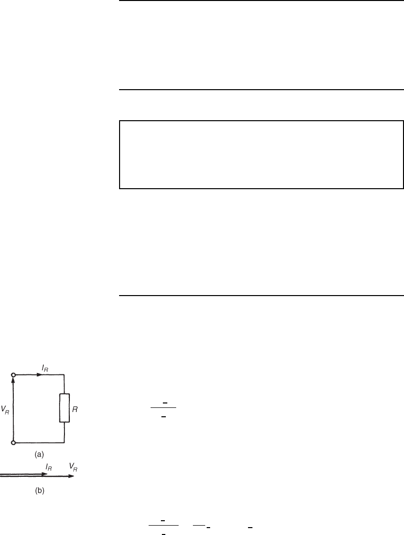
In an a.c. circuit containing resistance R only (see Figure 24.1(a)), the
current I
R
is in phase with the applied voltage V
R
as shown in the phasor
diagram of Figure 24.1(b). The phasor diagram may be superimposed on
the Argand diagram as shown in Figure 24.1(c). The impedance Z of the
circuit is given by
Z
=
V
R
66
0
°
I
R
66
0
°
= R
(b) Pure inductance
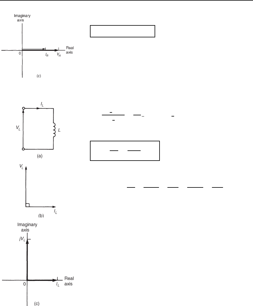
In an a.c. circuit containing pure inductance L only (see Figure 24.2(a)),
the current I
L
lags the applied voltage V
L
by 90
°
as shown in the phasor
diagram of Figure 24.2(b). The phasor diagram may be superimposed on
the Argand diagram as shown in Figure 24.2(c). The impedance Z of the
circuit is given by
Z D
V
L
6
90
°
I
L
6
0
°
D
V
L
I
L
6
90
°
D X
L
66
90
°
or jX
L
Figure 24.1 (a) Circuit
diagram (b) Phasor diagram
(c) Argand diagram
430 Electrical Circuit Theory and Technology
Figure 24.1 Continued
where X
L
is the inductive reactance given by
X
L
= !L = 2pfL ohms,
where f is the frequency in hertz and L is the inductance in henrys.
(c) Pure capacitance
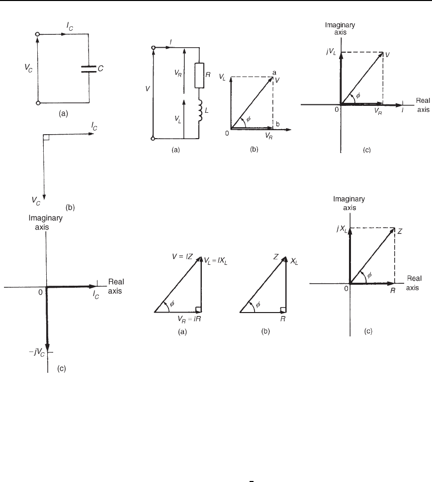
In an a.c. circuit containing pure capacitance only (see Figure 24.3(a)),
the current I
C
leads the applied voltage V
C
by 90
°
as shown in the phasor
diagram of Figure 24.3(b). The phasor diagram may be superimposed on
the Argand diagram as shown in Figure 24.3(c). The impedance Z of the
circuit is given by
Z D
V
C
6
90
°
I
C
6
0
°
D
V
C
I
C
6
90
°
D X
C
66
−90
°
or −jX
C
where X
C
is the capacitive reactance given by
X
C
=
1
!C
=
1
2pfC
ohms
where C is the capacitance in farads.
Note: jX
C
D
j
ωC
D
jj
ωCj
D
j
2
jωC
D
1
jωC
D
1
jωC
(d) R–L series circuit
In an a.c. circuit containing resistance R and inductance L in series (see
Figure 24.4(a)), the applied voltage V is the phasor sum of V
R
and V
L
as shown in the phasor diagram of Figure 24.4(b). The current I lags
the applied voltage V by an angle lying between 0
°
and 90
°
—the actual
value depending on the values of V
R
and V
L
, which depend on the values
of R and L. The circuit phase angle, i.e., the angle between the current
and the applied voltage, is shown as angle in the phasor diagram.
In any series circuit the current is common to all components and is
thus taken as the reference phasor in Figure 24.4(b). The phasor diagram
may be superimposed on the Argand diagram as shown in Figure 24.4(c),
where it may be seen that in complex form the supply voltage V is
given by:
V
= V
R
Y jV
L
Figure 24.5(a) shows the voltage triangle that is derived from the
phasor diagram of Figure 24.4(b) (i.e. triangle Oab). If each side of the
voltage triangle is divided by current I then the impedance triangle of
Figure 24.2 (a) Circuit
diagram (b) Phasor diagram
(c) Argand diagram
Application of complex numbers to series a.c. circuits 431
Figure 24.3 (a) Circuit
diagram (b) Phasor diagram
(c) Argand diagram
Figure 24.4 (a) Circuit diagram (b) Phasor diagram (c) Argand
diagram
Figure 24.5 (a) Voltage triangle (b) Impedance triangle (c) Argand
diagram
Figure 24.5(b) is derived. The impedance triangle may be superimposed
on the Argand diagram, as shown in Figure 24.5(c), where it may be seen
that in complex form the impedance Z is given by:
Z
= R Y jX
L
Thus, for example, an impedance expressed as 3 Cj4 means that the
resistance is 3 and the inductive reactance is 4
In polar form, Z DjZj
6
where, from the impedance triangle, the
modulus of impedance jZjD
R
2
C X
2
L
and the circuit phase angle
D arctanX
L
/R lagging
(e) R–C series circuit
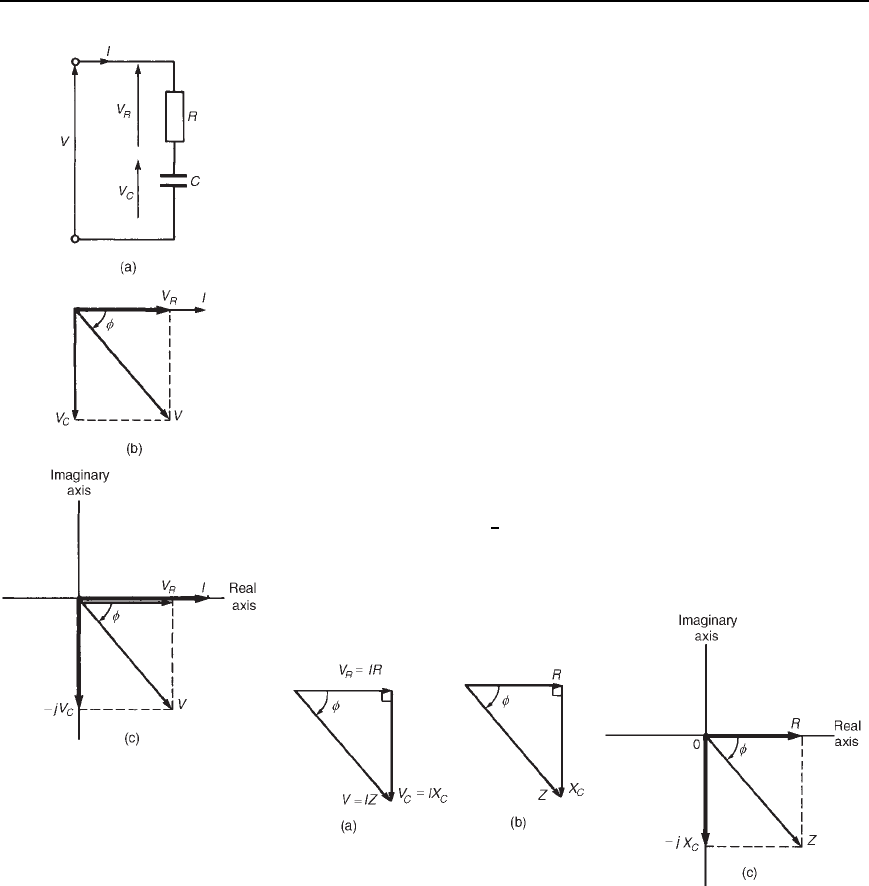
In an a.c. circuit containing resistance R and capacitance C in series
(see Figure 24.6(a)), the applied voltage V is the phasor sum of V
R
and
432 Electrical Circuit Theory and Technology
Figure 24.6 (a) Circuit
diagram (b) Phasor diagram
(c) Argand diagram
V
C
as shown in the phasor diagram of Figure 24.6(b). The current I
leads the applied voltage V by an angle lying between 0
°
and 90
°
—the
actual value depending on the values of V
R
and V
C
, which depend on
the values of R and C. The circuit phase angle is shown as angle in
the phasor diagram. The phasor diagram may be superimposed on the
Argand diagram as shown in Figure 24.6(c), where it may be seen that
in complex form the supply voltage V is given by:
V
= V
R
− jV
C
Figure 24.7(a) shows the voltage triangle that is derived from the phasor
diagram of Figure 24.6(b). If each side of the voltage triangle is divided
by current I, the impedance triangle is derived as shown in Figure 24.7(b).
The impedance triangle may be superimposed on the Argand diagram as
shown in Figure 24.7(c), where it may be seen that in complex form the
impedance Z is given by
Z
= R − jX
C
Thus, for example, an impedance expressed as 9 j14 means that
the resistance is 9 and the capacitive reactance X
C
is 14
In polar form, Z DjZj
6
where, from the impedance triangle,
jZjD
R
2
C X
2
C
and D arctanX
C
/R leading
Figure 24.7 (a) Voltage triangle (b) Impedance triangle (c) Argand
diagram
(f) R–L–C series circuit
In an a.c. circuit containing resistance R, inductance L and capacitance
C in series (see Figure 24.8(a)), the applied voltage V is the phasor sum
of V
R
, V
L
and V
C
as shown in the phasor diagram of Figure 24.8(b)
(where the condition V
L
>V
C
is shown). The phasor diagram may be
superimposed on the Argand diagram as shown in Figure 24.8(c), where
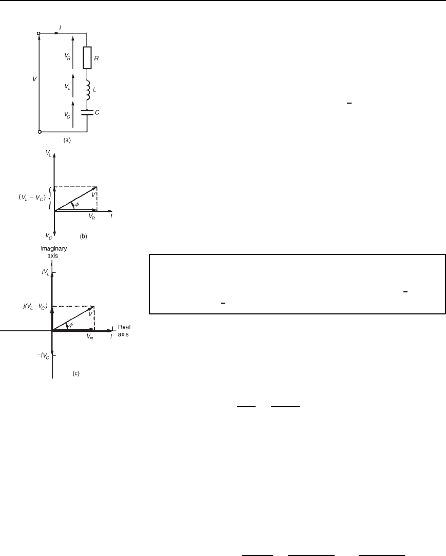
Application of complex numbers to series a.c. circuits 433
Figure 24.8 (a) Circuit
diagram (b) Phasor diagram
(c) Argand diagram
it may be seen that in complex form the supply voltage V is given by:
V
= V
R
Y j.V
L
− V
C
/
From the voltage triangle the impedance triangle is derived and superim-
posing this on the Argand diagram gives, in complex form,
impedance Z
= R Y j.X
L
− X
C
/ or Z = jZj
66
f
where, jZjD
[R
2
C X
L
X
C
2
]and D arctanX
L
X
C
/R
When V
L
D V
C
, X
L
D X
C
and the applied voltage V and the current
I are in phase. This effect is called series resonance and is discussed
separately in Chapter 28.
(g) General series circuit
In an a.c. circuit containing several impedances connected in series, say,
Z
1
,Z
2
,Z
3
,...,Z
n
, then the total equivalent impedance Z
T
is given by
Z
T
= Z
1
Y Z
2
Y Z
3
Y ...Y Z
n
Problem 1. Determine the values of the resistance and the
series-connected inductance or capacitance for each of the
following impedances: (a) 12 C j5 (b) j40 (c) 30
6
60
°
(d) 2.20 ð 10
6
6
30
°
. Assume for each a frequency of 50 Hz.
(a) From Section 24.2(d), for an R –L series circuit, impedance
Z D R C jX
L
.
Thus Z D 12 C j5 represents a resistance of 12 and an induc-
tive reactance of 5 in series.
Since inductive reactance X
L
D 2fL,
inductance L D
X
L
2f
D
5
250
D 0.0159 H
i.e., the inductance is 15.9 mH.
Thus an impedance .12 Y j5/Z represents a resistance of 12 Z
in series with an inductance of 15.9 mH.
(b) From Section 24.2(c), for a purely capacitive circuit, impedance
Z DjX
c
.
Thus Z Dj40 represents zero resistance and a capacitive reac-
tance of 40 .
Since capacitive reactance X
C
D 1/2fC,
capacitance C D
1
2fX
C
D
1
25040
F D
10
6
25040
µF
D 79.6
µF
434 Electrical Circuit Theory and Technology
Thus an impedance −j40 Z represents a pure capacitor of
capacitance 79.6 mF
(c) 30
6
60
°
D 30cos60
°
C j sin60
°
D 15 C j25.98
Thus Z D 30
6
60
°
D 15 C j25.98 represents a resistance of
15 and an inductive reactance of 25.98 in series (from
Section 24.2(d)).
Since X
L
D 2fL,
inductance L D
X
L
2f
D
25.98
250
D 0.0827 H or 82.7mH
Thus an impedance 30
66
60
°
Z represents a resistance of 15 Z in
series with an inductance of 82.7 mH
(d) 2.20 ð 10
6
6
30
°
D 2.20 ð 10
6
[cos30
°
C j sin30
°
]
D 1.905 ð 10
6
j1.10 ð 10
6
Thus Z D 2.20 ð10
6
6
30
°
D 1.905 ð 10
6
j1.10 ð10
6
re-
presents a resistance of 1.905 ð 10
6
(i.e. 1.905 M) and a capac-
itive reactance of 1.10 ð10
6
in series (from Section 24.2(e)).
Since capacitive reactance X
C
D 1/2fC,
capacitance C D
1
2fX
C
D
1
2501.10 ð 10
6
F
D 2.894 ð 10
9
F or 2.894 nF
Thus an impedance 2.2
× 10
6
66
−30
°
Z represents a resistance of
1.905 MZ in series with a 2.894 nF capacitor.
Problem 2. Determine, in polar and rectangular forms, the current
flowing in an inductor of negligible resistance and inductance
159.2 mH when it is connected to a 250 V, 50 Hz supply.
Inductive reactance X
L
D 2fL D 250159.2 ð 10
3
D 50
Thus circuit impedance Z D 0 C j50 D 50
6
90
°
Supply voltage, V D 250
6
0
°
V (or (250 C j0)V)
(Note that since the voltage is given as 250 V, this is assumed to mean
250
6
0
°
Vor(250C j0)V)
Hence current I D
V
Z
D
250
6
0
°
50
6
90
°
D
250
50
6
0
°
90
°
D 5
66
−90
°
A
Application of complex numbers to series a.c. circuits 435
Alternatively, I D
V
Z
D
250 C j0
0 C j50
D
250j50
j50j50
D
j50250
50
2
D −j5A
which is the same as 5
6
90
°
A
Problem 3. A 3 µF capacitor is connected to a supply of frequency
1 kHz and a current of 2.83
6
90
°
A flows. Determine the value of
the supply p.d.
Capacitive reactance X
C
D
1
2fC
D
1
210003 ð 10
6
D 53.05
Hence circuit impedance Z D 0 j53.05 D 53.05
6
90
°
Current I D 2.83
6
90
°
A(or0 C j2.83A
Supply p.d., V D IZ D 2.83
6
90
°
53.05
6
90
°
i.e. p.d.
= 150
66
0
°
V
Alternatively, V D IZ D 0 C j2.830 j53.05
Dj
2
2.8353.05 D 150 V
Problem 4. The impedance of an electrical circuit is 30 j50
ohms. Determine (a) the resistance, (b) the capacitance, (c) the
modulus of the impedance, and (d) the current flowing and its phase
angle, when the circuit is connected to a 240 V, 50 Hz supply.
(a) Since impedance Z D 30 j50, the resistance is 30 ohms and
the capacitive reactance is 50
(b) Since X
C
D 1/2fC, capacitance,
C D
1
2fX
C
D
1
25050
D 63.66 mF
(c) The modulus of impedance, jZjD
R
2
C X
2
C
D
30
2
C 50
2
D 58.31 Z
(d) Impedance Z D 30 j50 D 58.31
6
arctan
X
C
R
D 58.31
6
59.04
°
Hence current I D
V
Z
D
240
6
0
°
58.31
6
59.04
°
= 4.12
66
59.04
°
A
436 Electrical Circuit Theory and Technology
Figure 24.9
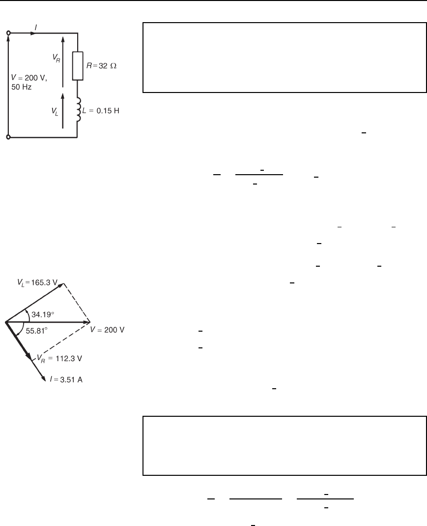
Problem 5. A 200 V, 50 Hz supply is connected across a coil
of negligible resistance and inductance 0.15 H connected in series
with a 32 resistor. Determine (a) the impedance of the circuit,
(b) the current and circuit phase angle, (c) the p.d. across the 32
resistor, and (d) the p.d. across the coil.
(a) Inductive reactance X
L
D 2fL D 2500.15 D 47.1
Impedance Z D R C jX
L
D .32 Y j47.1/Z or 57.0
66
55.81
°
Z
The circuit diagram is shown in Figure 24.9
(b) Current I D
V
Z
D
200
6
0
°
57.0
6
55.81
°
D 3.51
66
−55.81
°
A
i.e., the current is 3.51 A lagging the voltage by 55.81
°
(c) P.d. across the 32 resistor, V
R
D IR D 3.51
6
55.81
°
)32
6
0
°
i.e., V
R
= 112.3
66
−55.81
°
V
(d) P.d. across the coil, V
L
D IX
L
D 3.51
6
55.81
°
)47.1
6
90
°
i.e. V
L
= 165.3
66
34.19
°
V
The phasor sum of V
R
and V
L
is the supply voltage V as shown in the
phasor diagram of Figure 24.10.
V
R
D 112.3
6
55.81
°
D 63.11 j92.89 V
V
L
D 165.3
6
34.19
°
V D 136.73 C j92.89 V
Hence V D V
R
C V
L
D 63.11 j92.89 C 136.73 C j92.89
D 200 C j0 V or 200
6
0
°
V, correct to three significant
figures.
Figure 24.10
Problem 6. Determine the value of impedance if a current
of 7 C j16A flows in a circuit when the supply voltage is
(120 C j200)V. If the frequency of the supply is 5 MHz, determine
the value of the components forming the series circuit.
Impedance Z D
V
I
D
120 C j200
7 C j16
D
233.24
6
59.04
°
17.464
6
66.37
°
D 13.36
6
7.33 or 13.25 j1.705
The series circuit thus consists of a 13.25 Z resistor and a capacitor of
capacitive reactance 1.705 Z
Application of complex numbers to series a.c. circuits 437
Since X
C
D
1
2fC
, capacitance C D
1
2fX
C
D
1
25 ð 10
6
1.705
D 1.867 ð 10
8
F D 18.67 nF
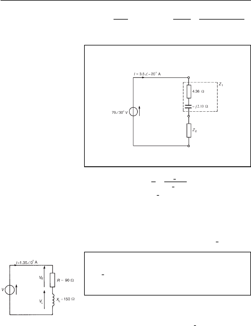
Problem 7. For the circuit shown in Figure 24.11, determine the
value of impedance Z
2
.
Figure 24.11
Total circuit impedance Z D
V
I
D
70
6
30
°
3.5
6
20
°
D 20
6
50
°
or 12.86 Cj15.32
Total impedance Z D Z
1
C Z
2
(see Section 24.2(g)).
Hence 12.86 C j15.32 D 4.36 j2.10 C Z
2
from which, impedance Z
2
D 12.86 C j15.32 4.36 j2.10
D .8.50 Y j17.42/Z or 19.38
66
63.99
°
Z
Problem 8. A circuit comprises a resistance of 90 in series with
an inductor of inductive reactance 150 . If the supply current is
1.35
6
0
°
A, determine (a) the supply voltage, (b) the voltage across
the 90 resistance, (c) the voltage across the inductance, and
(d) the circuit phase angle. Draw the phasor diagram.
The circuit diagram is shown in Figure 24.12
(a) Circuit impedance Z D R C jX
L
D 90 C j150 or
174.93
6
59.04
°
Figure 24.12
