Bird J. Electrical Circuit Theory and Technology
Подождите немного. Документ загружается.

396 Electrical Circuit Theory and Technology
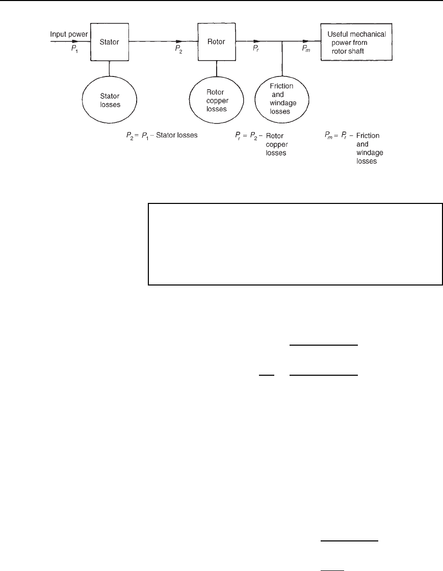
Figure 22.8
Problem 8. The power supplied to a three-phase induction motor
is 32 kW and the stator losses are 1200 W. If the slip is 5%,
determine (a) the rotor copper loss, (b) the total mechanical power
developed by the rotor, (c) the output power of the motor if friction
and windage losses are 750 W, and (d) the efficiency of the motor,
neglecting rotor iron loss.
(a) Input power to rotor D stator input power stator losses
D 32 kW 1.2kWD 30.8kW
From equation (22.9), slip D
rotor copper loss
rotor input
i.e.,
5
100
D
rotor copper loss
30.8
from which, rotor copper loss D 0.0530.8 D 1.54 kW
(b) Total mechanical power developed by the rotor
D rotor input power rotor losses
D 30.8 1.54 D 29.26 kW
(c) Output power of motor
D power developed by the rotor friction and windage losses
D 29.26 0.75 D 28.51 kW
(d) Efficiency of induction motor, D
output power
input power
ð 100%
D
28.51
32
ð 100% D 89.10%
Three-phase induction motors 397
Problem 9. The speed of the induction motor of Problem 8 is
reduced to 35% of its synchronous speed by using external rotor
resistance. If the torque and stator losses are unchanged, determine
(a) the rotor copper loss, and (b) the efficiency of the motor.
(a) Slip, s D
n
s
n
r
n
s
ð 100% D
n
s
0.35n
s
n
s
ð 100%
D 0.65100 D 65%
Input power to rotor D 30.8 kW (from Problem 8)
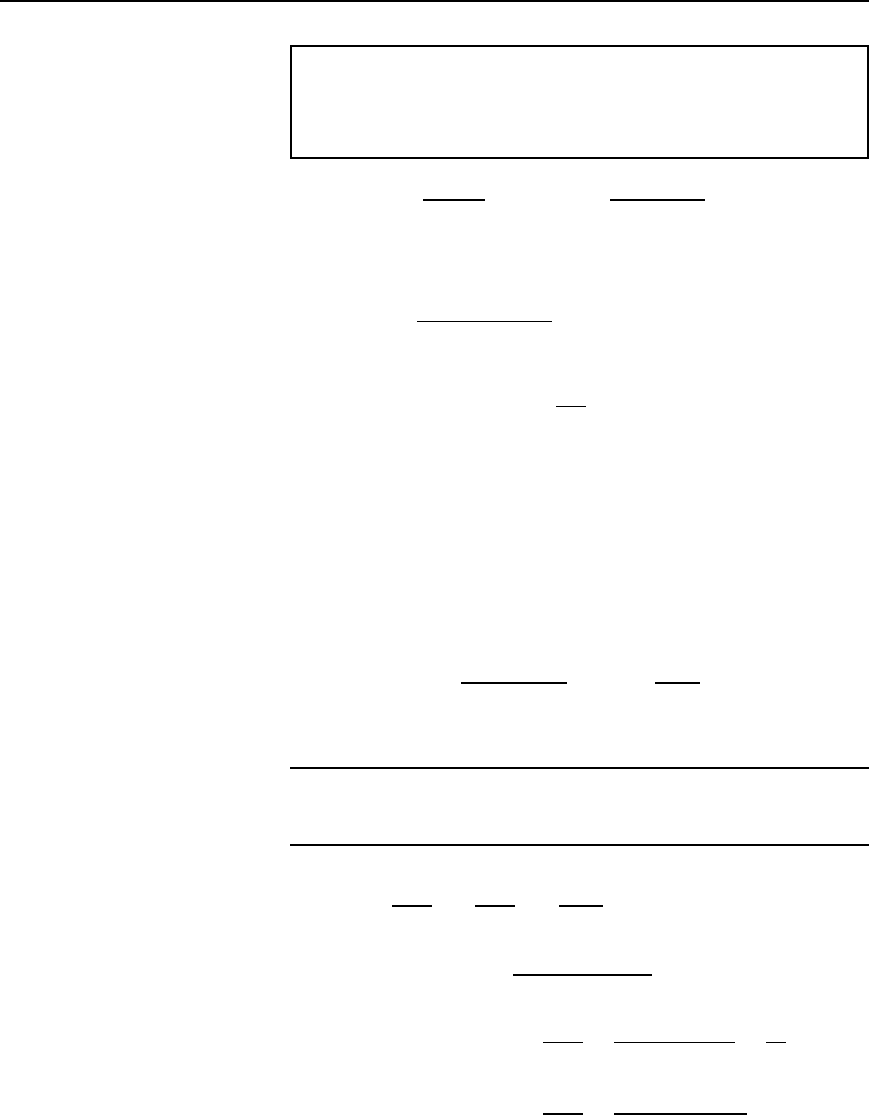
Since s D
rotor copper loss
rotor input
then rotor copper loss D s(rotor input)
D
65
100
30.8 D 20.02 kW
(b) Power developed by rotor
D input power to rotor rotor copper loss
D 30.8 20.02 D 10.78 kW
Output power of motor
D power developed by rotor friction and windage losses
D 10.78 0.75 D 10.03 kW
Efficiency, D
output power
input power
100% D
10.03
32
ð 100%
D 31.34%
Further problems on losses and efficiency may be found in Section 22.18,
problems 10 and 11, page 407.
22.11 Torque equation
for an induction motor
Torque T D
P
2
2n
s
D
1
2n
s
I
r
2
R
2
s
(from equation (22.10)
From equation (22.8), I
r
D
sN
2
/N
1
E
1
p
[R
2
2
C s X
2
2
]
Hence torque per phase, T D
1
2n
s
s
2
N
2
/N
1
2
E
1
2
R
2
2
C sX
2
2
R
2
s
i.e. T D
1
2n
s
sN
2
/N
1
2
E
1
2
R
2
R
2
2
C sX
2
2
398 Electrical Circuit Theory and Technology
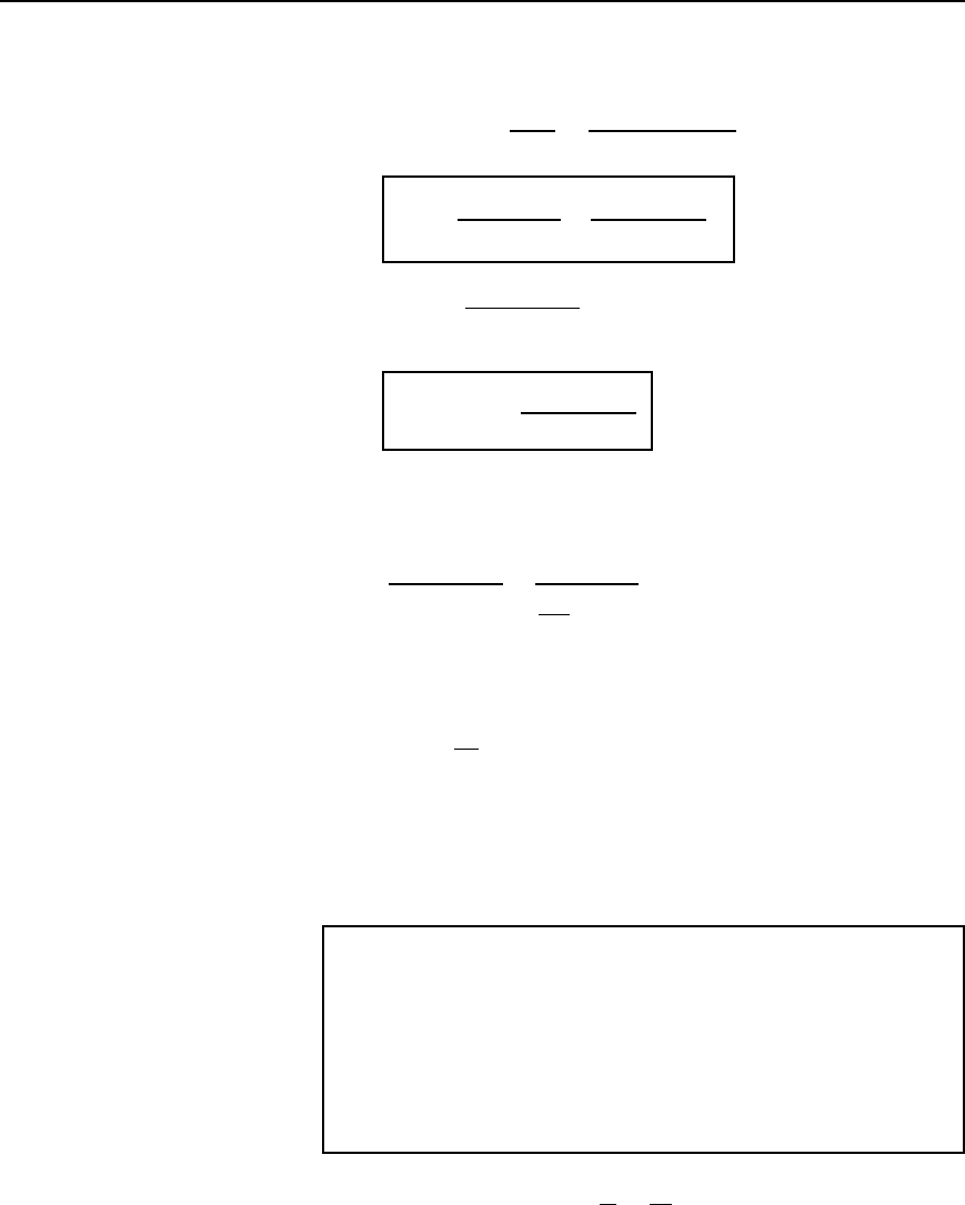
If there are m phases then
torque, T D
m
2n
s
sN
2
/N
1
2
E
1
2
R
2
R
2
2
C sX
2
2
i.e., T =
m.N
2
=N
1
/
2
2pn
s
sE
1
2
R
2
R
2
2
Y .sX
2
/
2
22.11
D k
sE
1
2
R
2
R
2
2
C sX
2
2
, where k is a constant for
a particular machine,
i.e.,
torque T ∝
sE
1
2
R
2
R
2
2
Y .sX
2
/
2
22.12
Under normal conditions, the supply voltage is usually constant, hence
equation (22.12) becomes:
T /
sR
2
R
2
2
C sX
2
2
/
R
2
R
2
2
s
C sX
2
2
The torque will be a maximum when the denominator is a minimum and
this occurs when R
2
2
/s D sX
2
2
i.e., when s D
R
2
X
2
or R
2
D sX
2
D X
r
from equation (22.4)
Thus maximum torque occurs when rotor resistance and rotor reactance
are equal, i.e., R
2
= X
r
Problems 10 to 13 following illustrate some of the characteristics of three-
phase induction motors.
Problem 10. A 415 V, three-phase, 50 Hz, 4 pole, star-connected
induction motor runs at 24 rev/s on full load. The rotor resistance
and reactance per phase are 0.35 " and 3.5 " respectively, and
the effective rotor-stator turns ratio is 0.85:1. Calculate (a) the
synchronous speed, (b) the slip, (c) the full load torque, (d) the
power output if mechanical losses amount to 770 W, (e) the
maximum torque, (f) the speed at which maximum torque occurs,
and (g) the starting torque.
(a) Synchronous speed, n
s
D
f
p
D
50
2
D 25 rev=s or 25 ð 60
D 1500 rev=min

Three-phase induction motors 399
(b) Slip, s D
n
s
n
r
n
s
D
25 24
25
D 0.04 or 4%
(c) Phase voltage, E
1
D
415
p
3
D 239.6 volts
Full load torque, T D
mN
2
/N
1
2
2n
s
sE
1
2
R
2
R
2
2
C s X
2
2
from equation (22.11)
D
3 0.85
2
225
0.04 239.6
2
0.35
0.35
2
C 0.04 ð3.5
2
D 0.01380
803.71
0.1421
D 78.05 Nm
(d) Output power, including friction losses, P
m
D 2n
r
T
D 22478.05
D 11770 watts
Hence power output D P
m
mechanical losses
D 11770 770 D 11 000 W D 11 kW
(e) Maximum torque occurs when R
2
D X
r
D 0.35 Z
Slip, s D
R
2
X
2
D
0.35
3.5
D 0.1
Hence maximum torque, T
m
D 0.01380
sE
1
2
R
2
R
2
2
C s X
2
2
from part (c)
D 0.01380
0.1 239.6
2
0.35
0.35
2
C 0.35
2
D 0.01380
2009.29
0.245
D 113.18 Nm
(f) For maximum torque, slip s D 0.1
Slip, s D
n
s
n
r
n
s
i.e., 0.1 D
25 n
r
25
Hence 0.125 D 25 n
r
and n
r
D 25 0.125
Thus speed at which maximum torque occurs,
n
r
D 25 2.5
D 22.5rev=s or 1350 rev=min
400 Electrical Circuit Theory and Technology
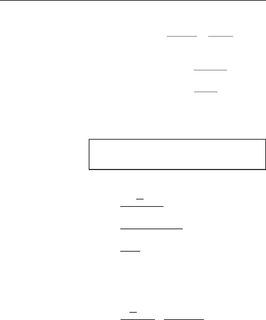
(g) At the start, i.e., at standstill, slip s D 1
Hence starting torque D
mN
2
/N
1
2
2n
s
E
1
2
R
2
R
2
2
C X
2
2
from equation (22.11) with s D 1
D 0.01380
239.6
2
0.35
0.35
2
C 3.5
2
D 0.01380
20092.86
12.3725
i.e., starting torque D 22.41 Nm
(Note that the full load torque (from part (c)) is 78.05 Nm but the starting
torque is only 22.41 Nm)
Problem 11. Determine for the induction motor in problem 10 at
full load, (a) the rotor current, (b) the rotor copper loss, and (c) the
starting current.
(a) From equation (22.8), rotor current,
I
r
D
s
N
2
N
1
E
1
[R
2
2
C s X
2
2
]
D
0.040.85239.6
[0.35
2
C 0.04 ð3.5
2
]
D
8.1464
0.37696
D 21.61 A
(b) Rotor copper loss per phase D I
r
2
R
2
D 21.61
2
0.35 D 163.45 W
Total copper loss (for 3 phases) D 3 ð 163.45 D 490.35 W
(c) From equation (22.7), starting current,
I
2
D
N
2
N
1
E
1
[R
2
2
C X
2
2
]
D
0.85239.6
[0.35
2
C 3.5
2
]
D 57.90 A
(Note that the starting current of 57.90 A is considerably higher than the
full load current of 21.61 A)
Three-phase induction motors 401
Problem 12. For the induction motor in problems 10 and 11, if
the stator losses are 650 W, determine (a) the power input at full
load, (b) the efficiency of the motor at full load and (c) the current
taken from the supply at full load, if the motor runs at a power
factor of 0.87 lagging.
(a) Output power P
m
D 11.770 kW from part (d), Problem 10
Rotor copper loss D 490.35 W D 0.49035 kW from part (b),
Problem 11
Stator input power, P
1
D P
m
C rotor copper loss
C rotor stator loss
D 11.770 C 0.49035 C 0.650 D 12.910 kW
(b) Net power output D 11 kW from part (d), Problem 10
Hence efficiency, D
output
input
ð 100% D
11
12.910
ð 100%
D 85.21%
(c) Power input, P
1
D
p
3 V
L
I
L
cos (see Chapter 19) and cos D
p.f. D 0.87
hence, supply current, I
L
D
P
1
p
3 V
L
cos
D
12.910 ð 1000
p
3 415 0.87
D 20.64 A
Problem 13. For the induction motor of Problems 10 to 12, deter-
mine the resistance of the rotor winding required for maximum
starting torque.
From equation (22.4), rotor reactance X
r
D sX
2
At the moment of starting, slip, s D 1
Maximum torque occurs when rotor reactance equals rotor resistance
hence for maximum torque, R
2
D X
r
D sX
2
D X
2
D 3.5 Z
Thus if the induction motor was a wound rotor type with slip rings
then an external star-connected resistance of 3.5 0.35"D 3.15 "
per phase could be added to the rotor resistance to give maximum torque
at starting (see Section 22.13).
Further problems on the torque equation may be found in Section 22.18,
problems 12 to 15, page 407.
22.12 Induction motor
torque–speed
characteristics
From Problem 10, parts (c) and (g), it is seen that the normal starting
torque may be less than the full load torque. Also, from Problem 10,
parts (e) and (f), it is seen that the speed at which maximum torque
402 Electrical Circuit Theory and Technology
occurs is determined by the value of the rotor resistance. At synchronous
speed, slip s D 0 and torque is zero. From these observations, the torque-
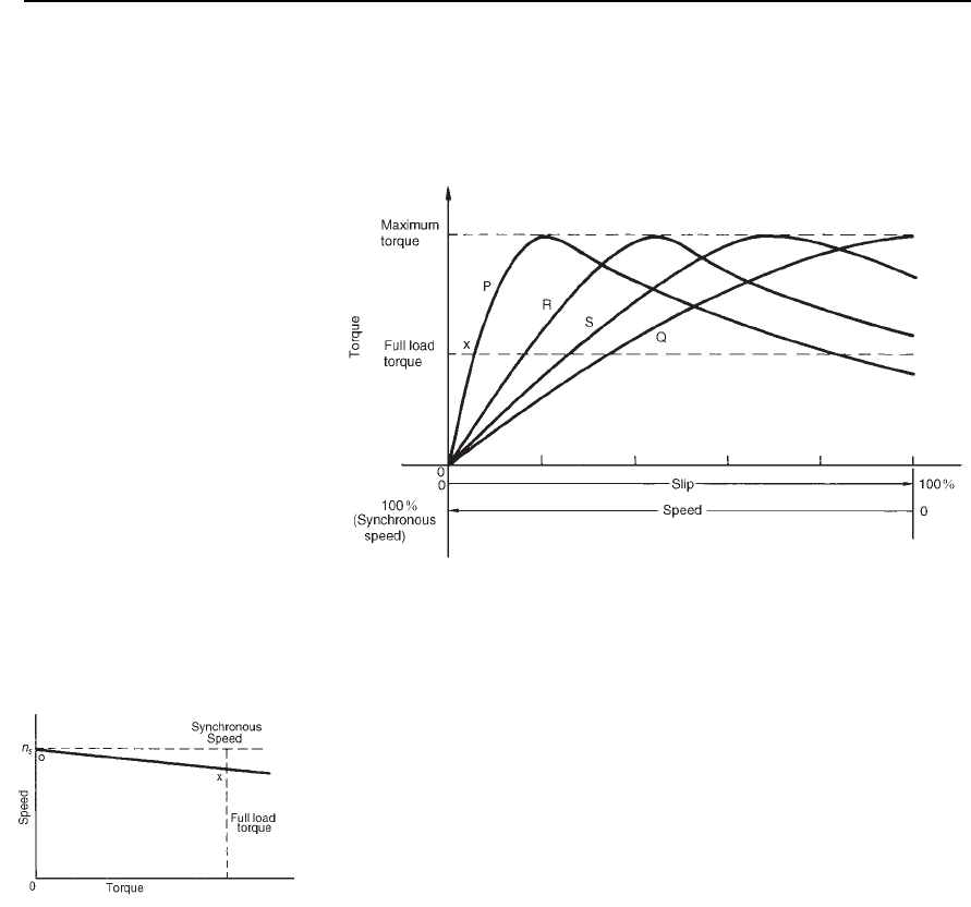
speed and torque-slip characteristics of an induction motor are as shown
in Figure 22.9.
Figure 22.9
The rotor resistance of an induction motor is usually small compared
with its reactance (for example, R
2
D 0.35 " and X
2
D 3.5 " in the above
Problems), so that maximum torque occurs at a high speed, typically about
80% of synchronous speed.
Curve P in Figure 22.9 is a typical characteristic for an induction motor.
The curve P cuts the full-load torque line at point X, showing that at full
load the slip is about 4–5%. The normal operating conditions are between
0 and X, thus it can be seen that for normal operation the speed variation
with load is quite small—the induction motor is an almost constant-
speed machine. Redrawing the speed-torque characteristic between 0 and
X gives the characteristic shown in Figure 22.10, which is similar to a
d.c. shunt motor as shown in chapter 21.
Figure 22.10
If maximum torque is required at starting then a high resistance rotor
is necessary, which gives characteristic Q in Figure 22.9. However, as
can be seen, the motor has a full load slip of over 30%, which results
in a drop in efficiency. Also such a motor has a large speed variation
with variations of load. Curves R and S of Figure 22.9 are characteristics
for values of rotor resistances between those of P and Q. Better starting
torque than for curve P is obtained, but with lower efficiency and with
speed variations under operating conditions.
A squirrel-cage induction motor would normally follow characteristic
P. This type of machine is highly efficient and about constant-speed under
normal running conditions. However it has a poor starting torque and
must be started off-load or very lightly loaded (see Section 22.13 below).
Also, on starting, the current can be four or five times the normal full
Three-phase induction motors 403
load current, due to the motor acting like a transformer with secondary
short circuited. In problem 11, for example, the current at starting was
nearly three times the full load current.
A wound-rotor induction motor would follow characteristic P when
the slip-rings are short-circuited, which is the normal running condition.
However, the slip-rings allow for the addition of resistance to the rotor
circuit externally and, as a result, for starting, the motor can have a char-
acteristic similar to curve Q in Figure 22.9 and the high starting current
experienced by the cage induction motor can be overcome.
In general, for three-phase induction motors, the power factor is usually
between about 0.8 and 0.9 lagging, and the full load efficiency is usually
about 80–90%.
From equation (22.12), it is seen that torque is proportional to the
square of the supply voltage. Any voltage variations therefore would seri-
ously affect the induction motor performance.
22.13 Starting methods
for induction motors
Squirrel-cage rotor
(i) Direct-on-line starting
With this method, starting current is high and may cause interfer-
ence with supplies to other consumers.
(ii) Auto transformer starting
With this method, an auto transformer is used to reduce
the stator voltage, E
1
, and thus the starting current (see
equation (22.7)). However, the starting torque is seriously reduced
(see equation (22.12)), so the voltage is reduced only sufficiently
to give the required reduction of the starting current. A typical
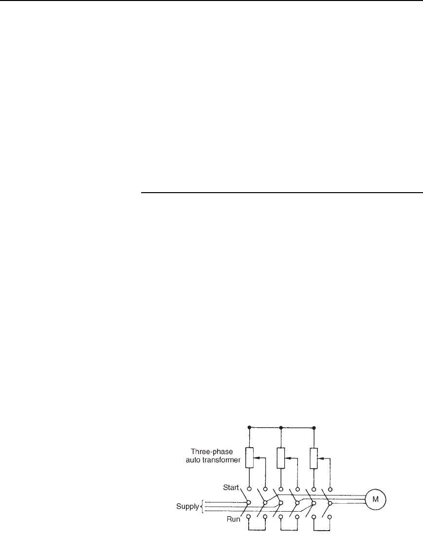
arrangement is shown in Figure 22.11. A double-throw switch
connects the auto transformer in circuit for starting, and when the
motor is up to speed the switch is moved to the run position which
connects the supply directly to the motor.
(iii) Star-delta starting
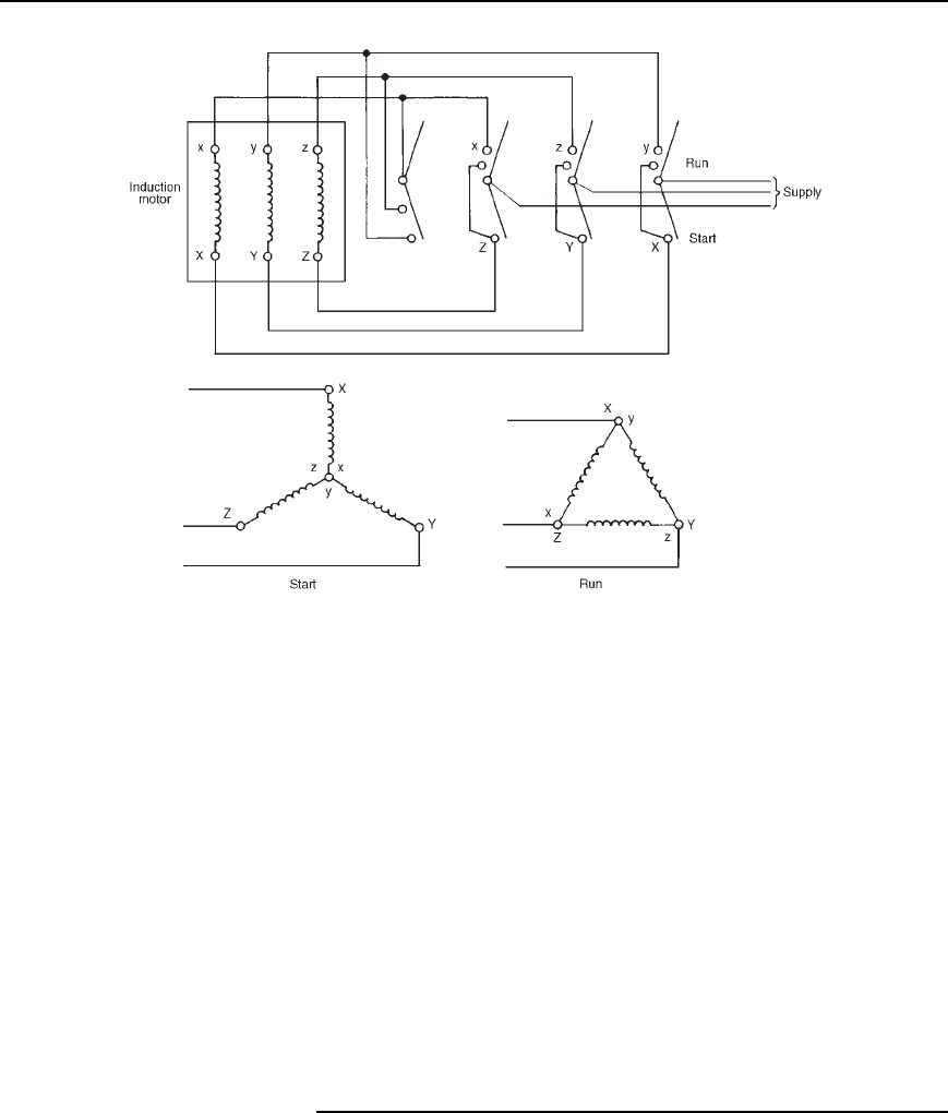
With this method, for starting, the connections to the stator phase
winding are star-connected, so that the voltage across each phase
Figure 22.11
404 Electrical Circuit Theory and Technology
Figure 22.12
winding is 1/
p
3 (i.e. 0.577) of the line voltage. For running, the
windings are switched to delta-connection. A typical arrangement
is shown in Figure 22.12. This method of starting is less expensive
than by auto transformer.
Wound rotor
When starting on load is necessary, a wound rotor induction motor must
be used. This is because maximum torque at starting can be obtained
by adding external resistance to the rotor circuit via slip rings, (see
problem 13). A face-plate type starter is used, and as the resistance is
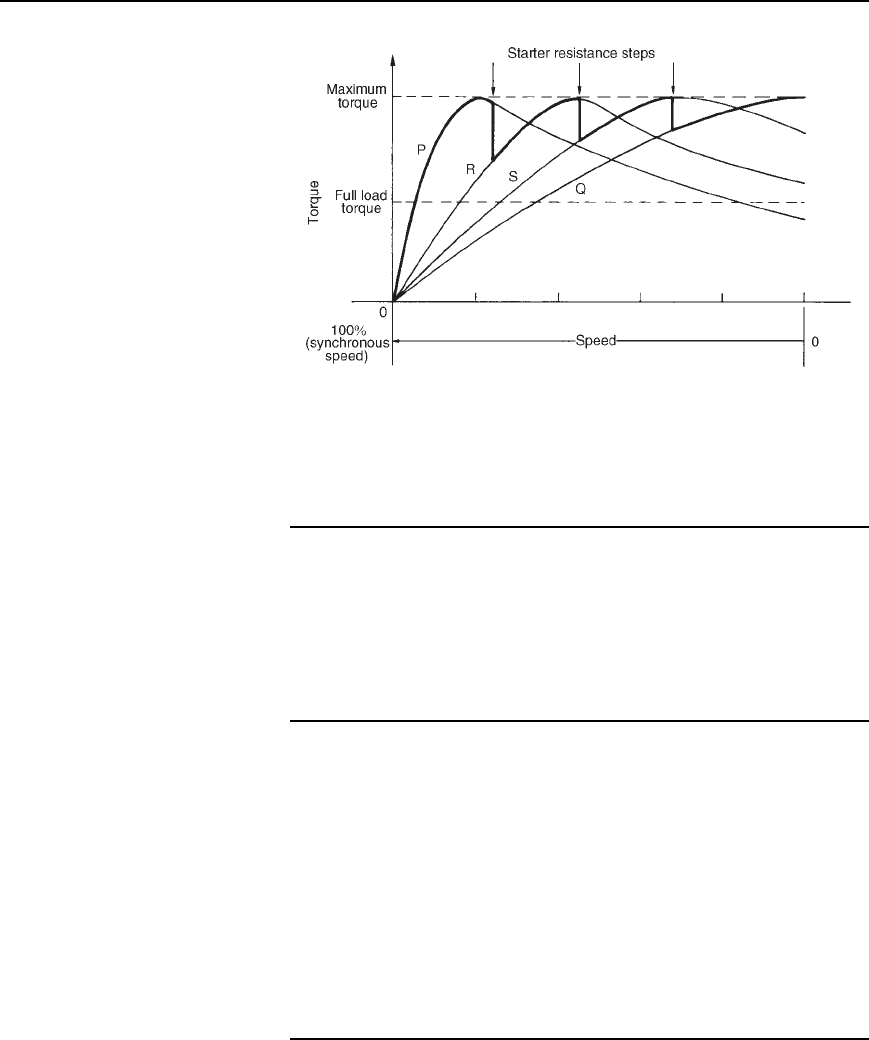
gradually reduced, the machine characteristics at each stage will be similar
to Q, S, R and P of Figure 22.13. At each resistance step, the motor oper-
ation will transfer from one characteristic to the next so that the overall
starting characteristic will be as shown by the bold line in Figure 22.13.
For very large induction motors, very gradual and smooth starting is
achieved by a liquid type resistance.
22.14 Advantages of
squirrel-cage induction
motors
The advantages of squirrel-cage motors compared with the wound rotor
type are that they:
(i) are cheaper and more robust
Three-phase induction motors 405
Figure 22.13
(ii) have slightly higher efficiency and power factor
(iii) are explosion-proof, since the risk of sparking is eliminated by the
absence of slip rings and brushes.
22.15 Advantages of
wound rotor induction
motor
The advantages of the wound rotor motor compared with the cage type
are that they:
(i) have a much higher starting torque
(ii) have a much lower starting current
(iii) have a means of varying speed by use of external rotor resistance.
22.16 Double cage
induction motor
The advantages of squirrel-cage and wound rotor induction motors are
combined in the double cage induction motor. This type of induction
motor is specially constructed with the rotor having two cages, one inside
the other. The outer cage has high resistance conductors so that maximum
torque is achieved at or near starting. The inner cage has normal low
resistance copper conductors but high reactance since it is embedded deep
in the iron core. The torque-speed characteristic of the inner cage is that
of a normal induction motor, as shown in Figure 22.14. At starting, the
outer cage produces the torque, but when running the inner cage produces
the torque. The combined characteristic of inner and outer cages is shown
in Figure 22.14. The double cage induction motor is highly efficient when
running.
22.17 Uses of three-phase
induction motors
Three-phase induction motors are widely used in industry and constitute
almost all industrial drives where a nearly constant speed is required,
from small workshops to the largest industrial enterprises.
