Bird J. Electrical Circuit Theory and Technology
Подождите немного. Документ загружается.


22 Three-phase induction
motors
At the end of this chapter you should be able to:
ž appreciate the merits of three-phase induction motors
ž understand how a rotating magnetic field is produced
ž state the synchronous speed, n
s
D f/p and use in
calculations
ž describe the principle of operation of a three-phase induction
motor
ž distinguish between squirrel-cage and wound-rotor types of
motor
ž understand how a torque is produced causing rotor movement
ž understand and calculate slip
ž derive expressions for rotor e.m.f., frequency, resistance,
reactance, impedance, current and copper loss, and use them
in calculations
ž state the losses in an induction motor and calculate efficiency
ž derive the torque equation for an induction motor, state the
condition for maximum torque, and use in calculations
ž describe torque-speed and torque-slip characteristics for an
induction motor
ž state and describe methods of starting induction motors
ž state advantages of cage rotor and wound rotor types of
induction motor
ž describe the double cage induction motor
ž state typical applications of three-phase induction motors
22.1 Introduction
In d.c. motors, introduced in Chapter 21, conductors on a rotating armature
pass through a stationary magnetic field. In a three-phase induction
motor, the magnetic field rotates and this has the advantage that no
external electrical connections to the rotor need be made. Its name is
derived from the fact that the current in the rotor is induced by the
magnetic field instead of being supplied through electrical connections to
the supply. The result is a motor which: (i) is cheap and robust, (ii) is
explosion proof, due to the absence of a commutator or slip-rings and
brushes with their associated sparking, (iii) requires little or no skilled
maintenance, and (iv) has self-starting properties when switched to a
Three-phase induction motors 387
supply with no additional expenditure on auxiliary equipment. The prin-
cipal disadvantage of a three-phase induction motor is that its speed cannot
be readily adjusted.
22.2 Production of a
rotating magnetic field
When a three-phase supply is connected to symmetrical three-phase wind-
ings, the currents flowing in the windings produce a magnetic field. This
magnetic field is constant in magnitude and rotates at constant speed as
shown below, and is called the synchronous speed.
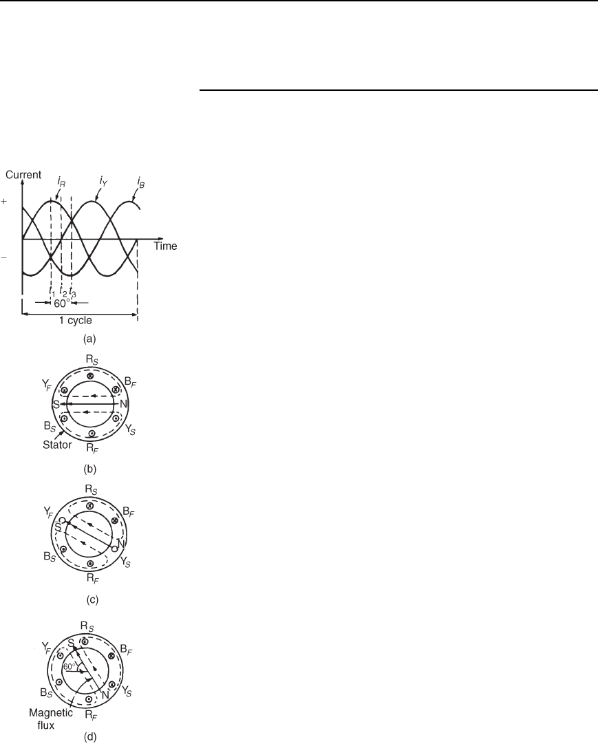
With reference to Figure 22.1, the windings are represented by three
single-loop conductors, one for each phase, marked R
S
R
F
, Y
S
Y
F
and
B
S
B
F
, the S and F signifying start and finish. In practice, each phase
winding comprises many turns and is distributed around the stator; the
single-loop approach is for clarity only.
When the stator windings are connected to a three-phase supply, the
current flowing in each winding varies with time and is as shown in
Figure 22.1(a). If the value of current in a winding is positive, the assump-
tion is made that it flows from start to finish of the winding, i.e., if it is
the red phase, current flows from R
S
to R
F
, i.e. away from the viewer in
R
S
and towards the viewer in R
F
. When the value of current is negative,
the assumption is made that it flows from finish to start, i.e. towards the
viewer in an ‘S’ winding and away from the viewer in an ‘F’ winding.
At time, say t
1
, shown in Figure 22.1(a), the current flowing in the red
phase is a maximum positive value. At the same time, t
1
, the currents
flowing in the yellow and blue phases are both 0.5 times the maximum
value and are negative.
The current distribution in the stator windings is therefore as shown
in Figure 22.1(b), in which current flows away from the viewer, (shown
as )inR
S
since it is positive, but towards the viewer (shown as þ )
in Y
S
and B
S
, since these are negative. The resulting magnetic field is as
shown, due to the ‘solenoid’ action and application of the corkscrew rule.
A short time later at time t
2
, the current flowing in the red phase has
fallen to about 0.87 times its maximum value and is positive, the current
in the yellow phase is zero and the current in the blue phase is about
0.87 times its maximum value and is negative. Hence the currents and
resultant magnetic field are as shown in Figure 22.1(c). At time t
3
, the
currents in the red and yellow phases are 0.5 of their maximum values and
the current in the blue phase is a maximum negative value. The currents
and resultant magnetic field are as shown in Figure 22.1(d).
Similar diagrams to Figure 22.1(b), (c) and (d) can be produced for all
time values and these would show that the magnetic field travels through
one revolution for each cycle of the supply voltage applied to the stator
windings. By considering the flux values rather than the current values,
it is shown below that the rotating magnetic field has a constant value of
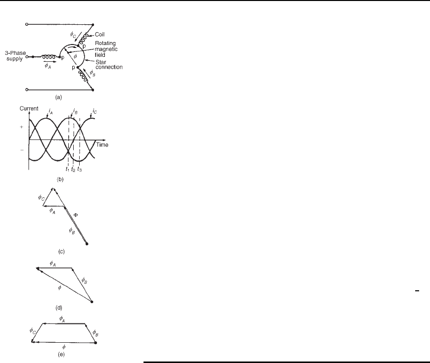
flux. The three coils shown in Figure 22.2(a), are connected in star to a
three-phase supply. Let the positive directions of the fluxes produced by
currents flowing in the coils, be
A
,
B
and
C
respectively. The directions
of
A
,
B
and
C
do not alter, but their magnitudes are proportional to
Figure 22.1
388 Electrical Circuit Theory and Technology
Figure 22.2
the currents flowing in the coils at any particular time. At time t
1
, shown
in Figure 22.2(b), the currents flowing in the coils are:
i
B
, a maximum positive value, i.e., the flux is towards point P;
i
A
and i
C
, half the maximum value and negative, i.e., the flux is away
from point P.
These currents give rise to the magnetic fluxes
A
,
B
and
C
, whose
magnitudes and directions are as shown in Figure 22.2(c). The resultant
flux is the phasor sum of
A
,
B
and
C
, shown as in Figure 22.2(c).
At time t
2
, the currents flowing are:
i
B
,0.866 ðmaximum positive value,i
C
, zero, and
i
A
,0.866 ð maximum negative value.
The magnetic fluxes and the resultant magnetic flux are as shown in
Figure 22.2(d).
At time t
3
,i
B
is 0.5 ð maximum value and is positive
i
A
is a maximum negative value, and
i
C
is 0.5 ð maximum value and is positive.
The magnetic fluxes and the resultant magnetic flux are as shown in
Figure 22.2(e).
Inspection of Figures 22.2(c), (d) and (e) shows that the magnitude
of the resultant magnetic flux, , in each case is constant and is 1
1
2
ð
the maximum value of
A
,
B
or
C
, but that its direction is changing.
The process of determining the resultant flux may be repeated for all
values of time and shows that the magnitude of the resultant flux is
constant for all values of time and also that it rotates at constant speed,
making one revolution for each cycle of the supply voltage.
22.3 Synchronous speed
The rotating magnetic field produced by three phase windings could have
been produced by rotating a permanent magnet’s north and south pole at
synchronous speed, (shown as N and S at the ends of the flux phasors in
Figures 22.1(b), (c) and (d)). For this reason, it is called a 2-pole system
and an induction motor using three phase windings only is called a 2-pole
induction motor.
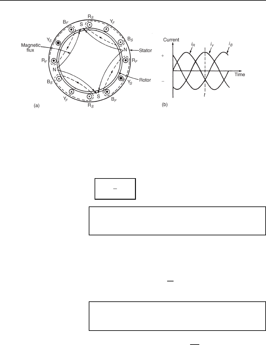
If six windings displaced from one another by 60
°
are used, as shown
in Figure 22.3(a), by drawing the current and resultant magnetic field
diagrams at various time values, it may be shown that one cycle of the
supply current to the stator windings causes the magnetic field to move
through half a revolution. The current distribution in the stator windings
are shown in Figure 22.3(a), for the time t shown in Figure 22.3(b).
It can be seen that for six windings on the stator, the magnetic flux
produced is the same as that produced by rotating two permanent magnet
north poles and two permanent magnet south poles at synchronous speed.
This is called a 4-pole system and an induction motor using six phase
Three-phase induction motors 389
Figure 22.3
windings is called a 4-pole induction motor. By increasing the number of
phase windings the number of poles can be increased to any even number.
In general, if f is the frequency of the currents in the stator windings
and the stator is wound to be equivalent to p pairs of poles, the speed of
revolution of the rotating magnetic field, i.e., the synchronous speed, n
s
is given by:
n
s
=
f
p
rev/s
Problem 1. A three-phase two-pole induction motor is connected
to a 50 Hz supply. Determine the synchronous speed of the motor
in rev/min.
From above, n
s
D f/p rev/s, where n
s
is the synchronous speed, f is
the frequency in hertz of the supply to the stator and p is the number of
pairs of poles. Since the motor is connected to a 50 hertz supply, f D 50.
The motor has a two-pole system, hence p, the number of pairs of poles
is one.
Thus, synchronous speed, n
s
D
50
1
D 50 rev/s D 50 ð 60 rev/min
D 3000 rev=min
Problem 2. A stator winding supplied from a three-phase 60 Hz
system is required to produce a magnetic flux rotating at
900 rev/min. Determine the number of poles.
Synchronous speed, n
s
D 900 rev/min D
900
60
rev/s D 15 rev/s
390 Electrical Circuit Theory and Technology
Since n
s
D
f
p
then p D
f
n
s
D
60
15
D 4
Hence the number of pole pairs is 4 and thus the number of poles is 8.
Problem 3. A three-phase 2-pole motor is to have a synchronous
speed of 6000 rev/min. Calculate the frequency of the supply
voltage.
Since n
s
D
f
p
then frequency, f D n
s
p
D
6000
60
2
2
D 100 Hz
Further problems on synchronous speed may be found in Section 22.18,
problems 1 to 3, page 406.
22.4 Construction of a
three-phase induction
motor
The stator of a three-phase induction motor is the stationary part corre-
sponding to the yoke of a d.c. machine. It is wound to give a 2-pole, 4-
pole, 6-pole, ...... rotating magnetic field, depending on the rotor speed
required. The rotor, corresponding to the armature of a d.c. machine, is
built up of laminated iron, to reduce eddy currents.
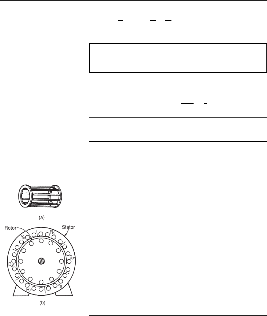
In the type most widely used, known as a squirrel-cage rotor, copper
or aluminium bars are placed in slots cut in the laminated iron, the ends
of the bars being welded or brazed into a heavy conducting ring, (see
Figure 22.4(a)). A cross-sectional view of a three-phase induction motor
is shown in Figure 22.4(b).
The conductors are placed in slots in the laminated iron rotor core. If
the slots are skewed, better starting and quieter running is achieved. This
type of rotor has no external connections which means that slip rings and
brushes are not needed. The squirrel-cage motor is cheap, reliable and
efficient.
Another type of rotor is the wound rotor. With this type there are
phase windings in slots, similar to those in the stator. The windings may
be connected in star or delta and the connections made to three slip rings.
The slip rings are used to add external resistance to the rotor circuit,
particularly for starting (see Section 22.13), but for normal running the
slip rings are short circuited.
The principle of operation is the same for both the squirrel cage and
the wound rotor machines.
Figure 22.4
22.5 Principle of
operation of a three-phase
induction motor
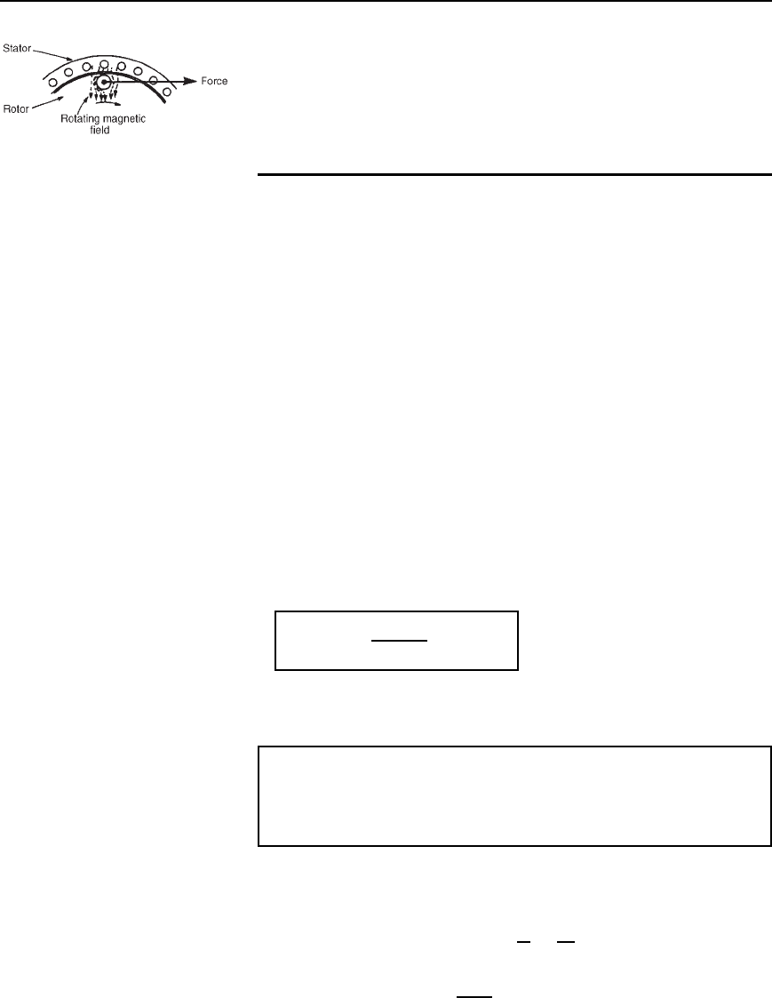
When a three-phase supply is connected to the stator windings, a rotating
magnetic field is produced. As the magnetic flux cuts a bar on the rotor, an
e.m.f. is induced in it and since it is joined, via the end conducting rings, to
Three-phase induction motors 391
Figure 22.5
another bar one pole pitch away, a current flows in the bars. The magnetic
field associated with this current flowing in the bars interacts with the
rotating magnetic field and a force is produced, tending to turn the rotor
in the same direction as the rotating magnetic field, (see Figure 22.5).
Similar forces are applied to all the conductors on the rotor, so that a
torque is produced causing the rotor to rotate.
22.6 Slip
The force exerted by the rotor bars causes the rotor to turn in the direc-
tion of the rotating magnetic field. As the rotor speed increases, the rate
at which the rotating magnetic field cuts the rotor bars is less and the
frequency of the induced e.m.f.’s in the rotor bars is less. If the rotor runs
at the same speed as the rotating magnetic field, no e.m.f.’s are induced
in the rotor, hence there is no force on them and no torque on the rotor.
Thus the rotor slows down. For this reason the rotor can never run at
synchronous speed.
When there is no load on the rotor, the resistive forces due to
windage and bearing friction are small and the rotor runs very nearly
at synchronous speed. As the rotor is loaded, the speed falls and this
causes an increase in the frequency of the induced e.m.f.’s in the rotor
bars and hence the rotor current, force and torque increase. The difference
between the rotor speed, n
r
, and the synchronous speed, n
s
, is called the
slip speed,i.e.
slip speed
= n
s
− n
r
rev=s
The ratio n
s
n
r
/n
s
is called the fractional slip or just the slip,s,and
is usually expressed as a percentage. Thus
slip, s =
n
s
− n
r
n
s
× 100%
Typical values of slip between no load and full load are about 4 to 5%
for small motors and 1.5 to 2% for large motors.
Problem 4. The stator of a 3-phase, 4-pole induction motor is
connected to a 50 Hz supply. The rotor runs at 1455 rev/min at
full load. Determine (a) the synchronous speed and (b) the slip at
full load.
(a) The number of pairs of poles, p D 4/2 D 2
The supply frequency f D 50 Hz
The synchronous speed, n
s
D
f
p
D
50
2
D 25 rev=s
(b) The rotor speed, n
r
D
1455
60
D 24.25 rev/s
392 Electrical Circuit Theory and Technology
The slip, s D
n
s
n
r
n
s
ð 100%
D
25 24.25
25
ð 100% D 3%
Problem 5. A 3-phase, 60 Hz induction motor has 2 poles. If the
slip is 2% at a certain load, determine (a) the synchronous speed,
(b) the speed of the rotor and (c) the frequency of the induced
e.m.f.’s in the rotor.
(a) f D 60 Hz, p D
2
2
D 1
Hence synchronous speed, n
s
D
f
p
D
60
1
D 60 rev=s
or 60 ð 60 D 3600 rev=min
(b) Since slip, s D
n
s
n
r
n
s
ð 100%
2 D
60 n
r
60
ð 100
Hence
2 ð 60
100
D 60 n
r
i.e. n
r
D 60
2 ð 60
100
D 58.8 rev/s
i.e. the rotor runs at 58.8 ð 60 D 3528 rev=min
(c) Since the synchronous speed is 60 rev/s and that of the rotor
is 58.8 rev/s, the rotating magnetic field cuts the rotor bars at
60 58.8, i.e. 1.2 rev/s.
Thus the frequency of the e.m.f.’s induced in the rotor bars is
1.2 Hz
Problem 6. A three-phase induction motor is supplied from a
50 Hz supply and runs at 1200 rev/min when the slip is 4%. Deter-
mine the synchronous speed.
Slip, s D
n
s
n
r
n
s
ð 100%
Rotor speed, n
r
D
1200
60
D 20 rev/s, and s D 4
Hence 4 D
n
s
20
n
s
ð 100%
Three-phase induction motors 393
or 0.04 D
n
s
20
n
s
from which, n
s
0.04 D n
s
20
and 20 D n
s
0.04 n
s
D n
s
1 0.04
Hence synchronous speed, n
s
D
20
1 0.04
D 20.8
P
3 rev/s
D 20.8
P
3 ð 60 rev/min D 1250 rev=min
Further problems on slip may be found in Section 22.18, problems 4 to 7,
page 406.
22.7 Rotor e.m.f. and
frequency
Rotor e.m.f.
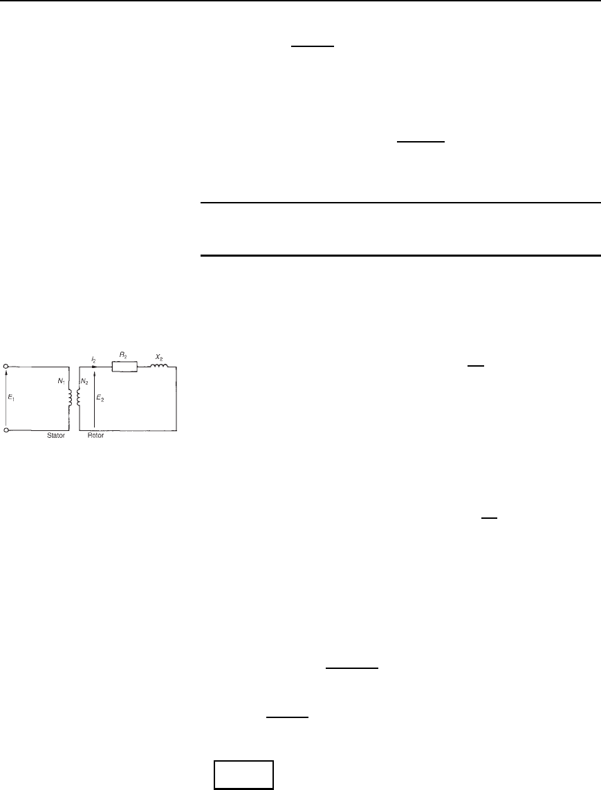
When an induction motor is stationary, the stator and rotor windings form
the equivalent of a transformer as shown in Figure 22.6.
The rotor e.m.f. at standstill is given by E
2
D
N
2
N
1
E
1
22.1
Figure 22.6
where E
1
is the supply voltage per phase to the stator.
When an induction motor is running, the induced e.m.f. in the rotor
is less since the relative movement between conductors and the rotating
field is less. The induced e.m.f. is proportional to this movement, hence
it must be proportional to the slip, s.
Hence when running, rotor e.m.f. per phase D E
r
D sE
2
D s
N
2
N
1
E
1
22.2
Rotor frequency
The rotor e.m.f. is induced by an alternating flux and the rate at which
the flux passes the conductors is the slip speed. Thus the frequency of the
rotor e.m.f. is given by:
f
r
D n
s
n
r
p D
n
s
n
r
n
s
n
s
p
However
n
s
n
r
n
s
is the slip s and n
s
p is the supply frequency f,
hence
f
r
= sf
22.3
394 Electrical Circuit Theory and Technology
Problem 7. The frequency of the supply to the stator of an 8-
pole induction motor is 50 Hz and the rotor frequency is 3 Hz.
Determine (a) the slip, and (b) the rotor speed.
(a) From equation (22.3), f
r
D sf
Hence 3 D s50
from which, slip, s D
3
50
D 0.06 or 6%
(b) Synchronous speed, n
s
D
f
p
D
50
4
D 12.5 rev/s
or 12.5 ð 60 D 750 rev/min
Slip, s D
n
s
n
r
n
s
, hence 0.06 D
12.5 n
r
12.5
0.0612.5 D 12.5 n
r
and rotor speed, n
r
D 12.5 0.0612.5
D 11.75 rev=s or 705 rev=min
Further problems on rotor frequency may be found in Section 22.18, prob-
lems 8 and 9, page 407.
22.8 Rotor impedance
and current
Rotor resistance
The rotor resistance R
2
is unaffected by frequency or slip, and hence
remains constant.
Rotor reactance
Rotor reactance varies with the frequency of the rotor current.
At standstill, reactance per phase, X
2
D 2fL
When running, reactance per phase, X
r
D 2f
r
L
D 2sfL from equation (22.3)
D s2fL
i.e.
X
r
= sX
2
22.4
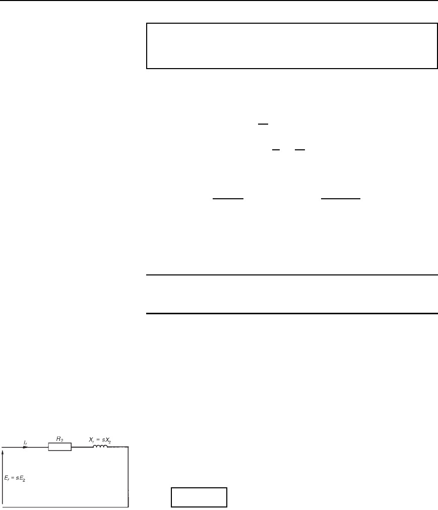
Figure 22.7 represents the rotor circuit when running.
Figure 22.7
Rotor impedance
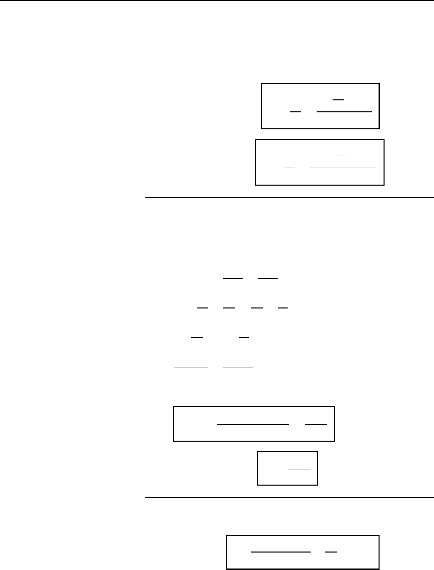
Rotor impedance per phase, Z
r
D
[R
2
2
C sX
2
2
] 22.5
Three-phase induction motors 395
At standstill, slip s D 1, then Z
2
D
R
2
2
C X
2
2
] 22.6
Rotor current
From Figures 22.6 and 22.7,
at standstill, starting current,
I
2
=
E
2
Z
2
=
N
2
N
1
E
1
p
[R
2
2
Y X
2
2
]
22.7
and when running, current,
I
r
=
E
r
Z
r
=
s
N
2
N
1
E
1
p
[R
2
2
Y .sX
2
/
2
]
22.8
22.9 Rotor copper loss
Power P D 2nT, where T is the torque in newton metres, hence torque
T D P/2n
If P
2
is the power input to the rotor from the rotating field, and P
m
is
the mechanical power output (including friction losses)
then T D
P
2
2n
s
D
P
m
2n
r
from which,
P
2
n
s
D
P
m
n
r
or
P
m
P
2
D
n
r
n
s
Hence 1
P
m
P
2
D 1
n
r
n
s
P
2
P
m
P
2
D
n
s
n
r
n
s
D s
P
2
P
m
is the electrical or copper loss in the rotor, i.e. P
2
P
m
D I
r
2
R
2
Hence
slip,s =
rotor copper loss
rotor input
=
I
r
2
R
2
P
2
22.9
or power input to the rotor,
P
2
=
I
r
2
R
2
s
22.10
22.10 Induction motor
losses and efficiency
Figure 22.8 summarizes losses in induction motors.
Motor efficiency,
D
output power
input power
D
P
m
P
1
ð 100%
