Bird J. Electrical Circuit Theory and Technology
Подождите немного. Документ загружается.


356 Electrical Circuit Theory and Technology
Problem 6. A d.c. generator running at 30 rev/s generates an
e.m.f. of 200 V. Determine the percentage increase in the flux per
pole required to generate 250 V at 20 rev/s.
From equation (21.2), generated e.m.f., E / ω and since ω D 2n,
E / n.
Let E
1
D 200 V,n
1
D 30 rev/s and flux per pole at this speed be
1
Let E
2
D 250 V,n
1
D 20 rev/s and flux per pole at this speed be
2
Since E / n then
E
1
E
2
D
1
n
1
2
n
2
Hence
200
250
D
1
30
2
20
from which,
2
D
1
30250
20200
D 1.875
1
Hence the increase in flux per pole needs to be 87.5%
Further problems on generated e.m.f. may be found in Section 21.17, prob-
lems 1 to 5, page 381.
21.6 D.c. generators
D.c. generators are classified according to the method of their field exci-
tation. These groupings are:
(i) Separately-excited generators, where the field winding is
connected to a source of supply other than the armature of its own
machine.
(ii) Self-excited generators, where the field winding receives its supply
from the armature of its own machine, and which are sub-divided
into (a) shunt, (b) series, and (c) compound wound generators.
21.7 Types of d.c.
generator and their
characteristics
(a) Separately-excited generator
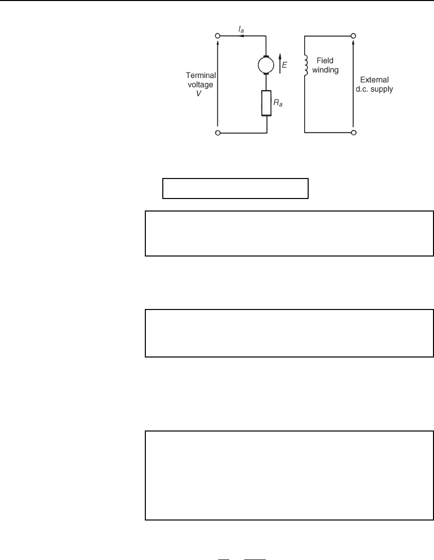
A typical separately-excited generator circuit is shown in Figure 21.5.
When a load is connected across the armature terminals, a load current I
a
will flow. The terminal voltage V will fall from its open-circuit e.m.f. E
due to a volt drop caused by current flowing through the armature resis-
tance, shown as R
a
, i.e.,
terminal voltage, V = E − I
a
R
a
D.c. machines 357
Figure 21.5
or
generated e.m.f., E = V Y I
a
R
a
21.3
Problem 7. Determine the terminal voltage of a generator which
develops an e.m.f. of 200 V and has an armature current of 30 A
on load. Assume the armature resistance is 0.30
With reference to Figure 21.5, terminal voltage,
V D E I
a
R
a
D 200 300.30 D 200 9 D 191 volts
Problem 8. A generator is connected to a 60 load and a current
of 8 A flows. If the armature resistance is 1 determine (a) the
terminal voltage, and (b) the generated e.m.f.
(a) Terminal voltage, V D I
a
R
L
D 860 D 480 volts
(b) Generated e.m.f., E D V C I
a
R
a
from equation (21.3)
D 480 C 81 D 480 C8 D 488 volts
Problem 9. A separately-excited generator develops a no-load
e.m.f. of 150 V at an armature speed of 20 rev/s and a flux per
pole of 0.10 Wb. Determine the generated e.m.f. when (a) the speed
increases to 25 rev/s and the pole flux remains unchanged, (b) the
speed remains at 20 rev/s and the pole flux is decreased to 0.08 Wb,
and (c) the speed increases to 24 rev/s and the pole flux is decreased
to 0.07 Wb.
(a) From Section 21.5, generated e.m.f. E / n
from which,
E
1
E
2
D
1
n
1
2
n
2
358 Electrical Circuit Theory and Technology
Hence
150
E
2
D
0.1020
0.1025
from which, E
2
D
1500.1025
0.1020
D 187.5 volts
(b)
150
E
3
D
0.1020
0.0820
from which, e.m.f., E
3
D
1500.0820
0.1020
D 120 volts
(c)
150
E
4
D
0.1020
0.0724
from which, e.m.f. E
4
D
1500.0724
0.1020
D 126 volts
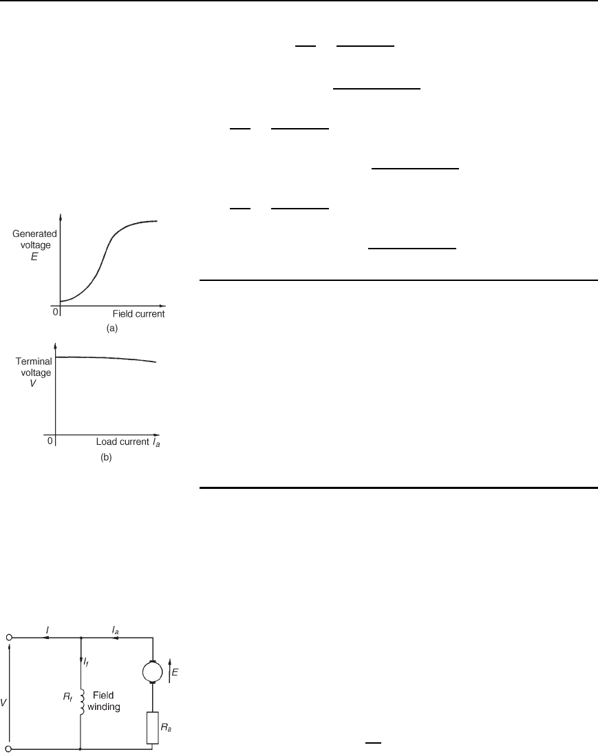
Characteristics
The two principal generator characteristics are the generated voltage/field
current characteristics, called the open-circuit characteristic and
the terminal voltage/load current characteristic, called the load
characteristic. A typical separately-excited generator open-circuit
characteristic is shown in Figure 21.6(a) and a typical load
characteristic is shown in Figure 21.6(b).
A separately-excited generator is used only in special cases, such as
when a wide variation in terminal p.d. is required, or when exact control of
the field current is necessary. Its disadvantage lies in requiring a separate
source of direct current.
Figure 21.6
(b) Shunt-wound generator
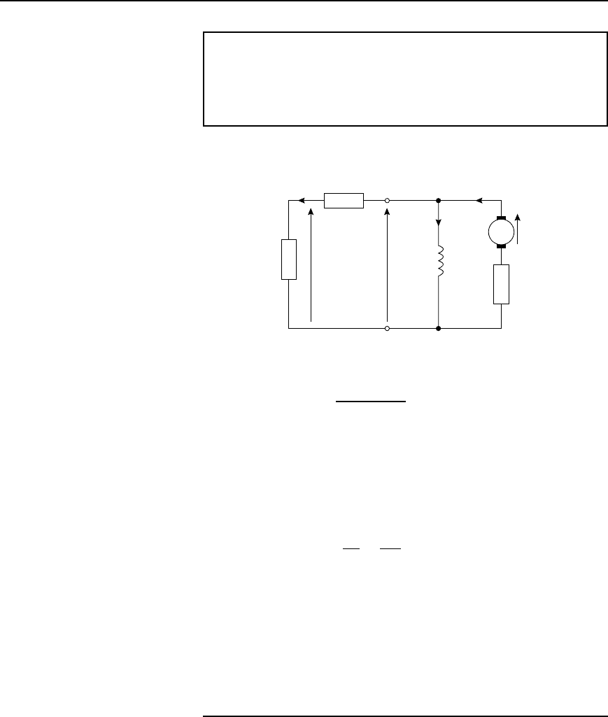
In a shunt wound generator the field winding is connected in parallel with
the armature as shown in Figure 21.7. The field winding has a relatively
high resistance and therefore the current carried is only a fraction of the
armature current.
For the circuit shown in Figure 21.7,
terminal voltage V D E I
a
R
a
or generated e.m.f., E D V C I
a
R
a
I
a
D I
f
C I, from Kirchhoff’s current law,
where I
a
D armature current
I
f
D field current
D
V
R
f
and I D load current
Figure 21.7
D.c. machines 359
Problem 10. A shunt generator supplies a 20 kW load at 200 V
through cables of resistance, R D 100 m. If the field winding
resistance, R
f
D 50 and the armature resistance, R
a
D 40 m,
determine (a) the terminal voltage, and (b) the e.m.f. generated in
the armature.
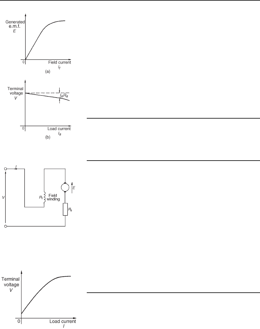
(a) The circuit is as shown in Figure 21.8.
I
R = 100 mΩ
I
a
I
f
E
R
f
= 50 Ω
R
a
= 40 mΩ
V200 V
LOAD
20 kW
Figure 21.8
Load current, I D
20000 watts
200 volts
D 100 A
Volt drop in the cables to the load D IR D 100100 ð 10
3
D 10 V
Hence terminal voltage, V D 200 C 10 D 210 volts
(b) Armature current I
a
D I
f
C I
Field current, I
f
D
V
R
f
D
210
50
D 4.2A
Hence I
a
D I
f
C I D 4.2 C100 D 104.2A
Generated e.m.f. E D V C I
a
R
a
D 210 C 104.240 ð 10
3
D 210 C 4.168
D 214.17 volts
Characteristics
The generated e.m.f., E, is proportional to ω, (see Section 21.5), hence
at constant speed, since ω D 2n, E / . Also the flux is proportional
360 Electrical Circuit Theory and Technology
Figure 21.9
to field current I
f
until magnetic saturation of the iron circuit of the
generator occurs. Hence the open circuit characteristic is as shown in
Figure 21.9(a).
As the load current on a generator having constant field current
and running at constant speed increases, the value of armature current
increases, hence the armature volt drop, I
a
R
a
increases. The generated
voltage E is larger than the terminal voltage V and the voltage equation
for the armature circuit is V D E I
a
R
a
. Since E is constant, V decreases
with increasing load. The load characteristic is as shown in Figure 21.9(b).
In practice, the fall in voltage is about 10% between no-load and full-load
for many d.c. shunt-wound generators.
The shunt-wound generator is the type most used in practice, but the
load current must be limited to a value that is well below the maximum
value. This then avoids excessive variation of the terminal voltage. Typical
applications are with battery charging and motor car generators.
(c) Series-wound generator
In the series-wound generator the field winding is connected in series
with the armature as shown in Figure 21.10.
Figure 21.10
Characteristic
The load characteristic is the terminal voltage/current characteristic. The
generated e.m.f. E, is proportional to ω and at constant speed ω (D
2n) is a constant. Thus E is proportional to . For values of current
below magnetic saturation of the yoke, poles, air gaps and armature core,
the flux is proportional to the current, hence E / I. For values of
current above those required for magnetic saturation, the generated e.m.f.
is approximately constant. The values of field resistance and armature
resistance in a series wound machine are small, hence the terminal voltage
V is very nearly equal to E. A typical load characteristic for a series
generator is shown in Figure 21.11.
In a series-wound generator, the field winding is in series with the
armature and it is not possible to have a value of field current when the
terminals are open circuited, thus it is not possible to obtain an open-
circuit characteristic.
Series-wound generators are rarely used in practise, but can be used as
a ‘booster’ on d.c. transmission lines.
(d) Compound-wound generator
In the compound-wound generator two methods of connection are used,
both having a mixture of shunt and series windings, designed to combine
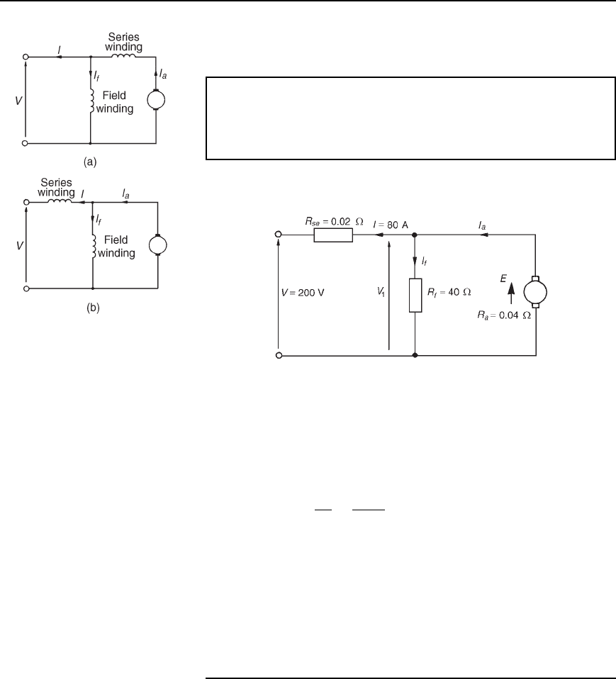
the advantages of each. Figure 21.12(a) shows what is termed a long-
shunt compound generator, and Figure 21.12(b) shows a short-shunt
Figure 21.11
D.c. machines 361
Figure 21.12
compound generator. The latter is the most generally used form of d.c.
generator.
Problem 11. A short-shunt compound generator supplies 80 A at
200 V. If the field resistance, R
f
D 40 , the series resistance,
R
Se
D 0.02 and the armature resistance, R
a
D 0.04 , determine
the e.m.f. generated.
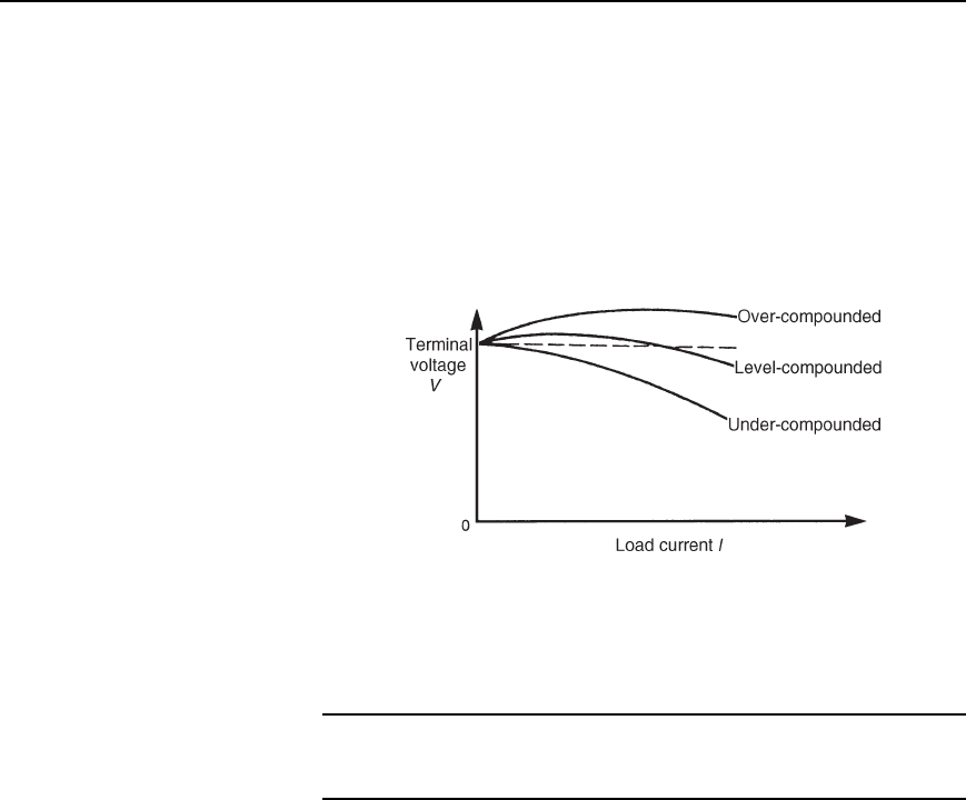
The circuit is shown in Figure 21.13.
Figure 21.13
Volt drop in series winding D IR
Se
D 800.02 D 1.6V
P.d. across the field winding D p.d. across armature
D V
1
D 200 C 1.6 D 201.6V
Field current I
f
D
V
1
R
f
D
201.6
40
D 5.04 A
Armature current, I
a
D I C I
f
D 80 C 5.04 D 85.04 A
Generated e.m.f., E D V
1
C I
a
R
a
D 201.6 C 85.040.04
D 201.6 C 3.4016
D 205 volts
Characteristics
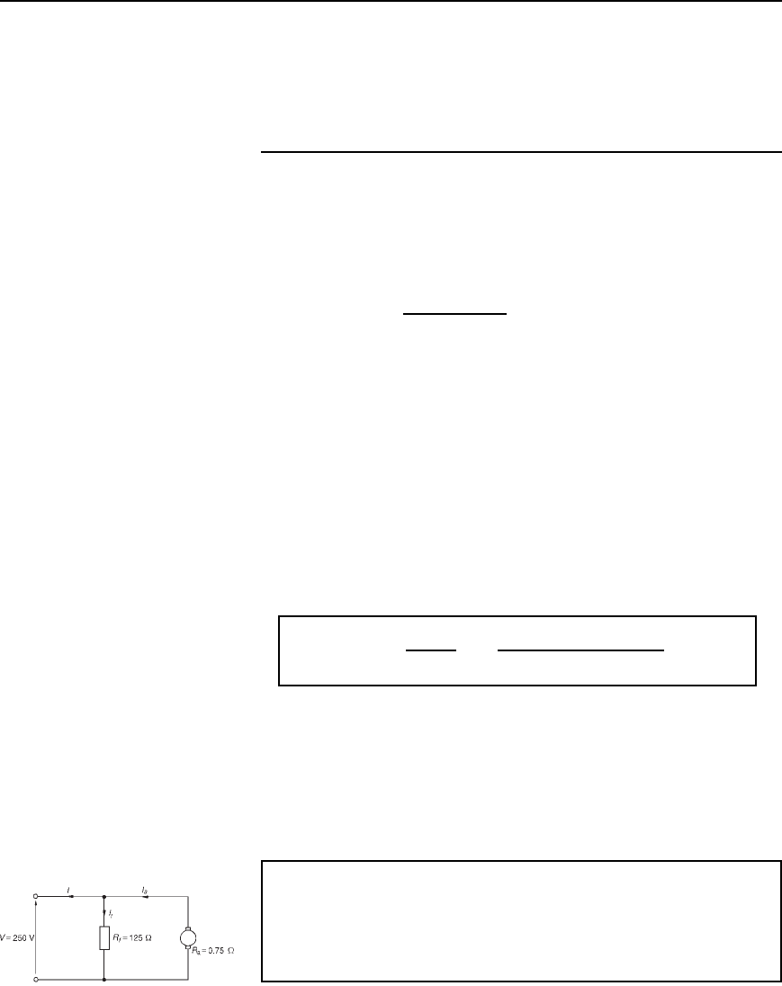
In cumulative-compound machines the magnetic flux produced by
the series and shunt fields are additive. Included in this group
are over-compounded, level-compounded and under-compounded
machines—the degree of compounding obtained depending on the
number of turns of wire on the series winding.
362 Electrical Circuit Theory and Technology
A large number of series winding turns results in an over-compounded
characteristic, as shown in Figure 21.14, in which the full-load terminal
voltage exceeds the no-load voltage. A level-compound machine gives a
full-load terminal voltage which is equal to the no-load voltage, as shown
in Figure 21.14.
An under-compounded machine gives a full-load terminal voltage
which is less than the no-load voltage, as shown in Figure 21.14. However
even this latter characteristic is a little better than that for a shunt
generator alone.
Figure 21.14
Compound-wound generators are used in electric arc welding, with
lighting sets and with marine equipment.
Further problems on the d.c. generator may be found in Section 21.17,
problems 6 to 11, page 382.
21.8 D.c. machine losses
As stated in Section 21.1, a generator is a machine for converting mechan-
ical energy into electrical energy and a motor is a machine for converting
electrical energy into mechanical energy. When such conversions take
place, certain losses occur which are dissipated in the form of heat.
The principal losses of machines are:
(i) Copper loss, due to I
2
R heat losses in the armature and field
windings.
(ii) Iron (or core) loss, due to hysteresis and eddy-current losses in the
armature. This loss can be reduced by constructing the armature of
silicon steel laminations having a high resistivity and low hysteresis
loss. At constant speed, the iron loss is assumed constant.
(iii) Friction and windage losses, due to bearing and brush contact
friction and losses due to air resistance against moving parts
(called windage). At constant speed, these losses are assumed to
be constant.
D.c. machines 363
(iv) Brush contact loss between the brushes and commutator. This loss
is approximately proportional to the load current.
The total losses of a machine can be quite significant and operating effi-
ciencies of between 80% and 90% are common.
21.9 Efficiency of a d.c.
generator
The efficiency of an electrical machine is the ratio of the output power to
the input power and is usually expressed as a percentage. The Greek letter,
‘’ (eta) is used to signify efficiency and since the units are power/power,
then efficiency has no units. Thus
efficiency,h
=
output power
input power
× 100%
If the total resistance of the armature circuit (including brush contact
resistance) is R
a
, then the total loss in the armature circuit is I
2
a
R
a
If the terminal voltage is V and the current in the shunt circuit is I
f
,
then the loss in the shunt circuit is I
f
V
If the sum of the iron, friction and windage losses is C then the total
losses is given by:
I
2
a
R
a
Y I
f
V Y C (I
2
a
R
a
C I
f
V is, in fact, the ‘copper loss’)
If the output current is I, then the output power is VI
Total input power D VI C I
2
a
R
a
C I
f
V C C. Hence
efficiency, h =
output
input
=
VI
VI Y I
2
a
R
a
Y I
f
V Y C
× 100%
(21.4)
The efficiency of a generator is a maximum when the load is such that:
I
2
a
R
a
= VI
f
Y C
i.e., when the variable loss D the constant loss
Problem 12. A 10 kW shunt generator having an armature circuit
resistance of 0.75 and a field resistance of 125 , generates a
terminal voltage of 250 V at full load. Determine the efficiency of
the generator at full load, assuming the iron, friction and windage
losses amount to 600 W.
The circuit is shown in Figure 21.15.
Figure 21.15

364 Electrical Circuit Theory and Technology
Output power D 10000 W D VI
from which, load current I D
10000
V
D
10000
250
D 40 A
Field current, I
f
D
V
R
f
D
250
125
D 2A
Armature current, I
a
D I
f
C I D 2 C40 D 42 A
Efficiency, D
VI
VI C I
2
a
R
a
C I
f
V C C
ð 100%
D
10000
10000 C 42
2
0.75 C 2250 C 600
ð 100%
D
10000
12423
ð 100% D 80.50%
A further problem on the efficiency of a d.c. generator may be found in
Section 21.17, problem 12, page 382.
21.10 D.c. motors
The construction of a d.c. motor is the same as a d.c. generator. The only
difference is that in a generator the generated e.m.f. is greater than the
terminal voltage, whereas in a motor the generated e.m.f. is less than the
terminal voltage.
D.c. motors are often used in power stations to drive emergency stand-
by pump systems which come into operation to protect essential equipment
and plant should the normal a.c. supplies or pumps fail.
Back e.m.f.
When a d.c. motor rotates, an e.m.f. is induced in the armature conductors.
By Lenz’s law this induced e.m.f. E opposes the supply voltage V and is
called a back e.m.f., and the supply voltage, V is given by:
V = E Y I
a
R
a
or E = V − I
a
R
a
21.5
Problem 13. A d.c. motor operates from a 240 V supply. The
armature resistance is 0.2 . Determine the back e.m.f. when the
armature current is 50 A.
For a motor, V D E C I
a
R
a
hence back e.m.f., E D V I
a
R
a
D 240 500.2 D 240 10 D 230 volts

D.c. machines 365
Problem 14. The armature of a d.c. machine has a resistance of
0.25 and is connected to a 300 V supply. Calculate the e.m.f.
generated when it is running: (a) as a generator giving 100 A, and
(b) as a motor taking 80 A.
(a) As a generator, generated e.m.f.,
E D V C I
a
R
a
, from equation (21.3),
D 300 C 1000.25
D 300 C 25 D 325 volts
(b) As a motor, generated e.m.f. (or back e.m.f.),
E D V I
a
R
a
, from equation (21.5),
D 300 800.25 D 280 volts
Further problems on back e.m.f. may be found in Section 21.17, prob-
lems 13 to 15, page 383.
21.11 Torque of a d.c.
machine
From equation (21.5), for a d.c. motor, the supply voltage V is given by
V D E C I
a
R
a
Multiplying each term by current I
a
gives:
VI
a
D EI
a
C I
2
a
R
a
The term VI
a
is the total electrical power supplied to the armature,
the term I
2
a
R
a
is the loss due to armature resistance,
and the term EI
a
is the mechanical power developed by the armature
If T is the torque, in newton metres, then the mechanical power devel-
oped is given by Tω watts (see ‘Science for Engineering’).
Hence Tω D 2nT D EI
a
from which,
torque T =
EI
a
2pn
newton metres
21.6
From Section 21.5, equation (21.1), the e.m.f. E generated is given by
E D
2pnZ
c
Hence 2nT D EI
a
D
2pnZ
c
I
a
