Bird J. Electrical Circuit Theory and Technology
Подождите немного. Документ загружается.

326 Electrical Circuit Theory and Technology
(iv) Radio frequency (r.f.) transformers, operating in the MHz
frequency region have either an air core, a ferrite core or a dust
core. Ferrite is a ceramic material having magnetic properties
similar to silicon steel, but having a high resistivity. Dust cores
consist of fine particles of carbonyl iron or permalloy (i.e. nickel
and iron), each particle of which is insulated from its neighbour.
Applications of r.f. transformers are found in radio and television
receivers.
(v) Transformer windings are usually of enamel-insulated copper or
aluminium.
(vi) Cooling is achieved by air in small transformers and oil in large
transformers.
20.7 Equivalent circuit
of a transformer
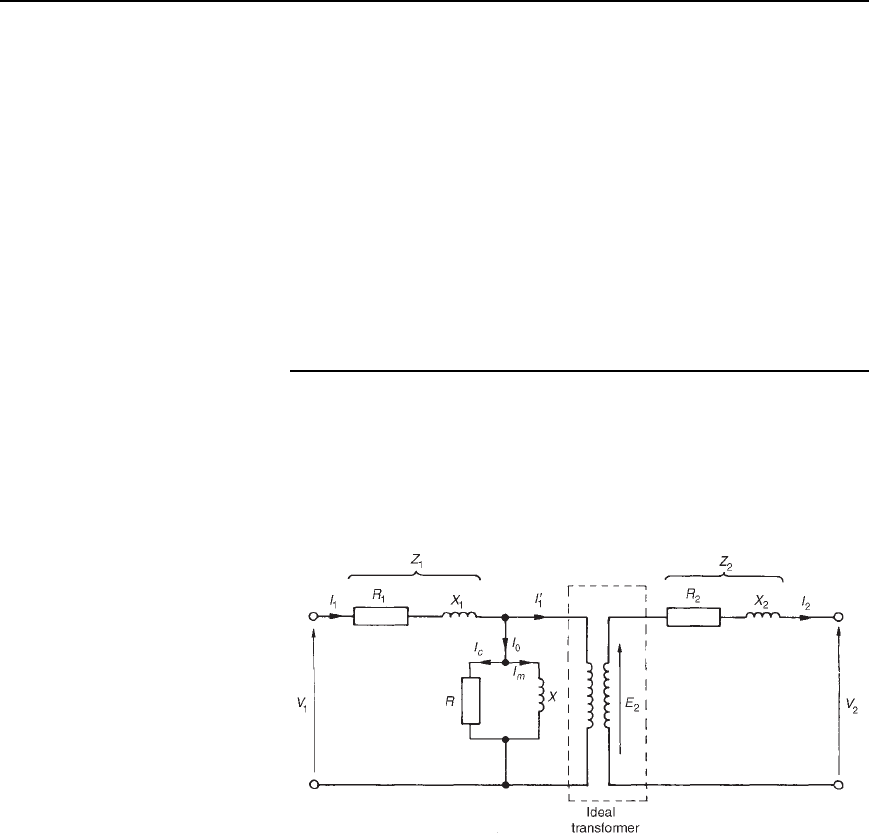
Figure 20.7 shows an equivalent circuit of a transformer. R
1
and R
2
repre-
sent the resistances of the primary and secondary windings and X
1
and
X
2
represent the reactances of the primary and secondary windings, due
to leakage flux.
Figure 20.7
The core losses due to hysteresis and eddy currents are allowed for by
resistance R which takes a current I
c
, the core loss component of the
primary current. Reactance X takes the magnetizing component I
M
.
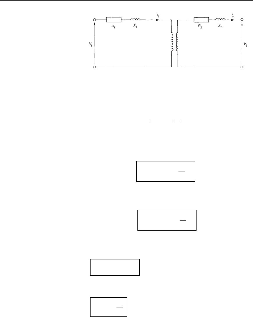
In a simplified equivalent circuit shown in Figure 20.8, R and X are
omitted since the no-load current I
0
is normally only about 3–5% of the
full load primary current.
It is often convenient to assume that all of the resistance and reactance
as being on one side of the transformer.
Resistance R
2
in Figure 20.8 can be replaced by inserting an addi-
tional resistance R
0
2
in the primary circuit such that the power absorbed
Transformers 327
Figure 20.8
in R
0
2
when carrying the primary current is equal to that in R
2
due to the
secondary current, i.e., I
2
1
R
0
2
D I
2
2
R
2
from which, R
0
2
D R
2
I
2
I
1
2
D R
2
V
1
V
2
2
Then the total equivalent resistance in the primary circuit R
e
is equal
to the primary and secondary resistances of the actual transformer.
Hence
R
e
D R
1
C R
0
2
, i.e.,
R
e
= R
1
Y R
2
V
1
V
2
2
20.6
By similar reasoning, the equivalent reactance in the primary circuit is
given by
X
e
D X
1
C X
0
2
, i.e.,
X
e
= X
1
Y X
2
V
1
V
2
2
20.7
The equivalent impedance Z
e
of the primary and secondary windings
referred to the primary is given by
Z
e
=
.R
2
e
Y X
2
e
/
20.8
If
e
is the phase angle between I
1
and the volt drop I
1
Z
e
then
cosf
e
=
R
e
Z
e
20.9
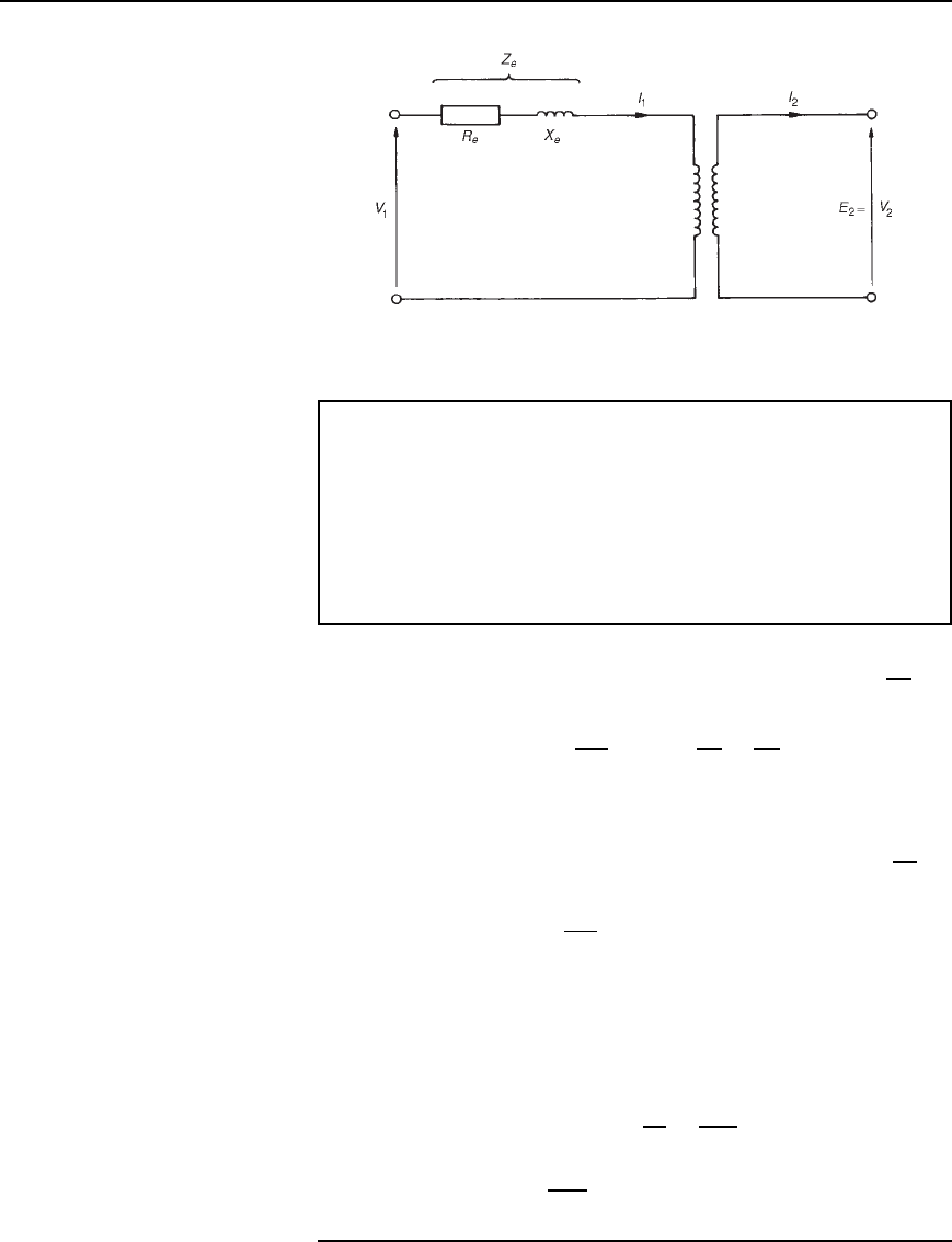
The simplified equivalent circuit of a transformer is shown in Figure 20.9.
328 Electrical Circuit Theory and Technology
Figure 20.9
Problem 13. A transformer has 600 primary turns and 150
secondary turns. The primary and secondary resistances are 0.25
and 0.01 respectively and the corresponding leakage reactances
are 1.0 and 0.04 respectively. Determine (a) the equivalent
resistance referred to the primary winding, (b) the equivalent
reactance referred to the primary winding, (c) the equivalent
impedance referred to the primary winding, and (d) the phase angle
of the impedance.
(a) From equation (20.6), equivalent resistance R
e
D R
1
C R
2
V
1
V
2
2
i.e., R
e
D 0.25 C 0.01
600
150
2
since
V
1
V
2
D
N
1
N
2
D 0.41 Z
(b) From equation (20.7), equivalent reactance, X
e
D X
1
C X
2
V
1
V
2
2
i.e., X
e
D 1.0 C 0.04
600
150
2
D 1.64 Z
(c) From equation (20.8), equivalent impedance, Z
e
D
R
2
e
C X
2
e
D
0.41
2
C 1.64
2
D 1.69 Z
(d) From equation (20.9), cos
e
D
R
e
Z
e
D
0.41
1.69
Hence
e
D arccos
0.41
1.69
D 75.96
°
Transformers 329
A further problem on the equivalent circuit of a transformer may be found
in Section 20.16, problem 18, page 346.
20.8 Regulation of a
transformer
When the secondary of a transformer is loaded, the secondary terminal
voltage, V
2
, falls. As the power factor decreases, this voltage drop
increases. This is called the regulation of the transformer anditis
usually expressed as a percentage of the secondary no-load voltage, E
2
.
For full-load conditions:
Regulation =
E
2
− V
2
E
2
× 100% 20.10
The fall in voltage, E
2
V
2
, is caused by the resistance and reactance
of the windings.
Typical values of voltage regulation are about 3% in small transformers
and about 1% in large transformers.
Problem 14. A 5 kVA, 200 V/400 V, single-phase transformer
has a secondary terminal voltage of 387.6 volts when loaded.
Determine the regulation of the transformer.
From equation (20.10):
regulation D
(No-load secondary voltage
terminal voltage on load)
no-load secondary voltage
ð 100%
D
400 387.6
400
ð 100%
D
12.4
400
ð 100% D 3.1%
Problem 15. The open circuit voltage of a transformer is 240 V.
A tap changing device is set to operate when the percentage regu-
lation drops below 2.5%. Determine the load voltage at which the
mechanism operates.
Regulation D
(no load voltage terminal load voltage)
no load voltage
ð 100%
Hence 2.5 D
240 V
2
240
100%

330 Electrical Circuit Theory and Technology
Therefore
2.5240
100
D 240 V
2
i.e, 6 D 240 V
2
from which, load voltage, V
2
D 240 6 D 234 volts
Further problems on regulation may be found in Section 20.16, prob-
lems 19 and 20, page 346.
20.9 Transformer losses
and efficiency
There are broadly two sources of losses in transformers on load, these
being copper losses and iron losses.
(a) Copper losses are variable and result in a heating of the conductors,
due to the fact that they possess resistance. If R
1
and R
2
are the
primary and secondary winding resistances then the total copper
loss is I
2
1
R
1
C I
2
2
R
2
(b) Iron losses are constant for a given value of frequency and flux
density and are of two types — hysteresis loss and eddy current loss.
(i) Hysteresis loss is the heating of the core as a result of
the internal molecular structure reversals which occur as the
magnetic flux alternates. The loss is proportional to the area of
the hysteresis loop and thus low loss nickel iron alloys are used
for the core since their hysteresis loops have small areas.(See
Chapters 7 and 38)
(ii) Eddy current loss is the heating of the core due to e.m.f.’s
being induced not only in the transformer windings but also
in the core. These induced e.m.f.’s set up circulating currents,
called eddy currents. Owing to the low resistance of the core,
eddy currents can be quite considerable and can cause a large
power loss and excessive heating of the core. Eddy current
losses can be reduced by increasing the resistivity of the core
material or, more usually, by laminating the core (i.e., splitting
it into layers or leaves) when very thin layers of insulating
material can be inserted between each pair of laminations. This
increases the resistance of the eddy current path, and reduces
the value of the eddy current.
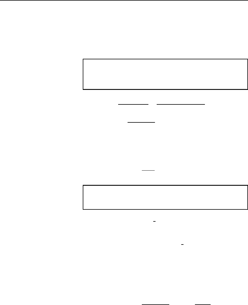
Transformer efficiency, D
output power
input power
D
input power—losses
input power
h = 1 −
losses
input power
20.11
Transformers 331
and is usually expressed as a percentage. It is not uncommon for power
transformers to have efficiencies of between 95% and 98%.
Output power D V
2
I
2
cos
2
,
total losses D copper loss Ciron losses,
and input power D output power C losses
Problem 16. A 200 kVA rated transformer has a full-load copper
loss of 1.5 kW and an iron loss of 1 kW. Determine the transformer
efficiency at full load and 0.85 power factor.
Efficiency D
output power
input power
D
input power —losses
input power
D 1
losses
input power
Full-load output power D VI cos D 2000.85 D 170 kW
Total losses D 1.5 C 1.0 D 2.5kW
Input power D output power C losses D 170 C2.5 D 172.5kW
Hence efficiency D
1
2.5
172.5
D 1 0.01449 D 0.9855 or 98.55%
Problem 17. Determine the efficiency of the transformer in
Problem 16 at half full-load and 0.85 power factor.
Half full-load power output D
1
2
2000.85 D 85 kW
Copper loss (or I
2
R loss) is proportional to current squared.
Hence the copper loss at half full-load is
1
2
2
1500 D 375 W
Iron loss D 1000 W (constant)
Total losses D 375 C 1000 D 1375 W or 1.375 kW
Input power at half full-load D output power at half full-load C losses
D 85 C 1.375 D 86.375 kW
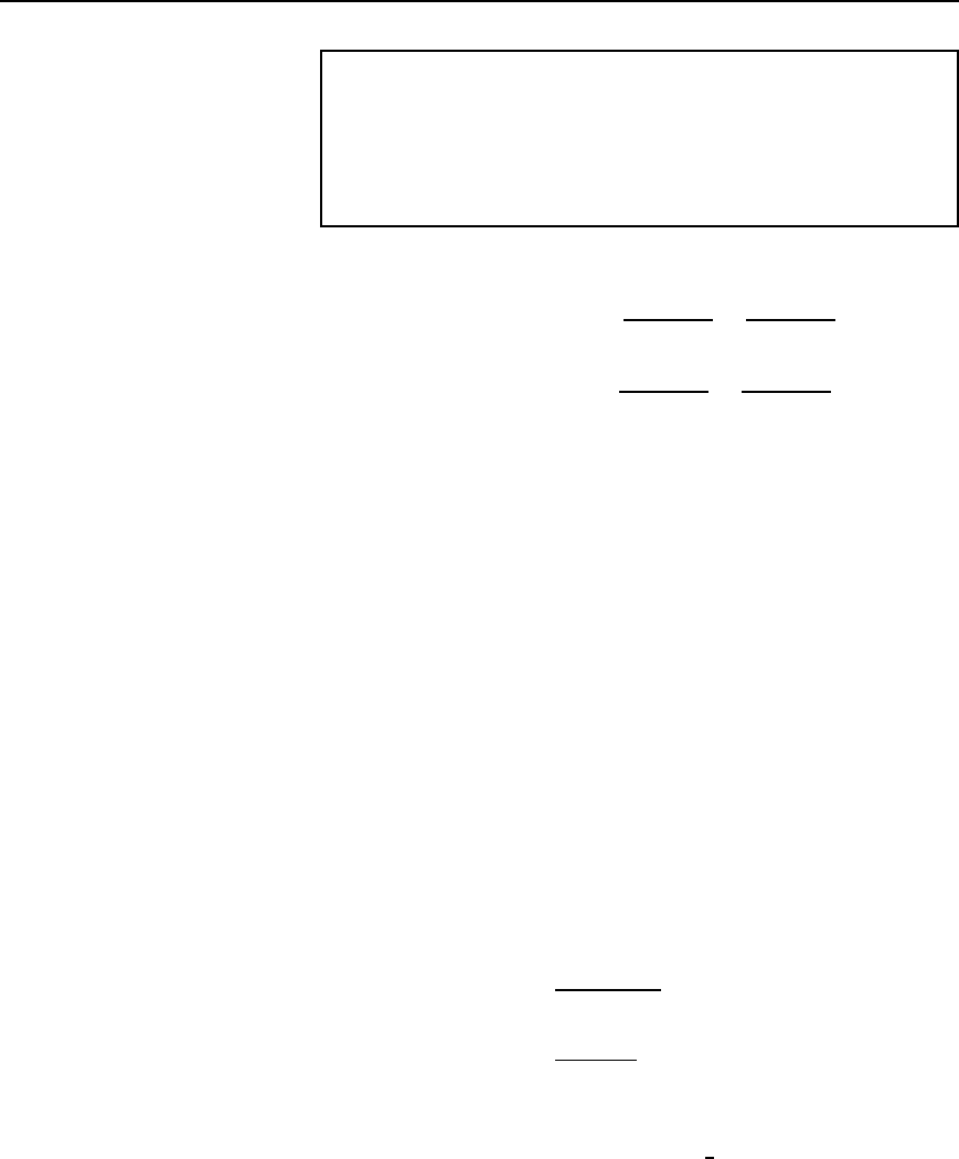
Hence efficiency D
1
losses
input power
D
1
1.375
86.375
D 1 0.01592 D 0.9841 or 98.41%
332 Electrical Circuit Theory and Technology
Problem 18. A 400 kVA transformer has a primary winding resis-
tance of 0.5 and a secondary winding resistance of 0.001 . The
iron loss is 2.5 kW and the primary and secondary voltages are
5 kV and 320 V respectively. If the power factor of the load is
0.85, determine the efficiency of the transformer (a) on full load,
and (b) on half load.
(a) Rating D 400 kVA D V
1
I
1
D V
2
I
2
Hence primary current, I
1
D
400 ð 10
3
V
1
D
400 ð 10
3
5000
D 80 A
and secondary current, I
2
D
400 ð 10
3
V
2
D
400 ð 10
3
320
D 1250 A
Total copper loss D I
2
1
R
1
C I
2
2
R
2
,
where R
1
D 0.5 and R
2
D 0.001
D 80
2
0.5 C 1250
2
0.001
D 3200 C 1562.5 D 4762.5 watts
On full load, total loss D copper loss C iron loss
D 4762.5 C 2500
D 7262.5WD 7.2625 kW
Total output power on full load D V
2
I
2
cos
2
D 400 ð 10
3
0.85
D 340 kW
Input power D output power C losses D 340 kW C 7.2625 kW
D 347.2625 kW
Efficiency, D
1
losses
input power
ð 100%
D
1
7.2625
347.2625
ð 100% D 97.91%
(b) Since the copper loss varies as the square of the current, then total
copper loss on half load D 4762.5 ð
1
2
2
D 1190.625 W
Hence total loss on half load D 1190.625 C 2500
D 3690.625 W or 3.691 kW
Transformers 333
Output power on half full load D
1
2
340 D 170 kW
Input power on half full load D output power C losses
D 170 kW C 3.691 kW
D 173.691 kW
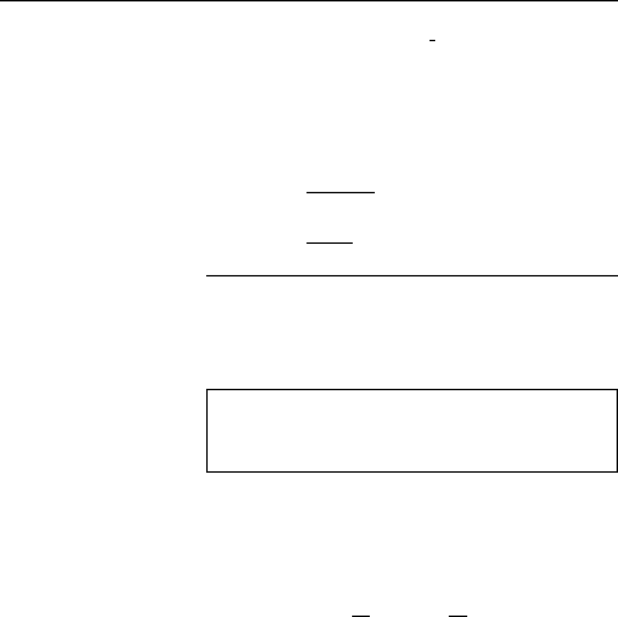
Hence efficiency at half full load,
D
1
losses
input power
ð 100%
D
1
3.691
173.691
ð 100% D 97.87%
Maximum efficiency
It may be shown that the efficiency of a transformer is a maximum when
the variable copper loss (i.e., I
2
1
R
1
C I
2
2
R
2
) is equal to the constant iron
losses.
Problem 19. A 500 kVA transformer has a full load copper loss of
4 kW and an iron loss of 2.5 kW. Determine (a) the output kVA at
which the efficiency of the transformer is a maximum, and (b) the
maximum efficiency, assuming the power factor of the load is 0.75.
(a) Let x be the fraction of full load kVA at which the efficiency is a
maximum.
The corresponding total copper loss D 4kWx
2
At maximum efficiency, copper loss D iron loss Hence
4x
2
D 2.5
from which x
2
D
2.5
4
and x D
2.5
4
D 0.791
Hence the output kVA at maximum efficiency D 0.791 ð 500
D 395.5kVA
(b) Total loss at maximum efficiency D 2 ð 2.5 D 5kW
Output power D 395.5kVAð p.f. D 395.5 ð 0.75 D 296.625 kW
Input power D output power C losses
D 296.625 C 5 D 301.625 kW
334 Electrical Circuit Theory and Technology
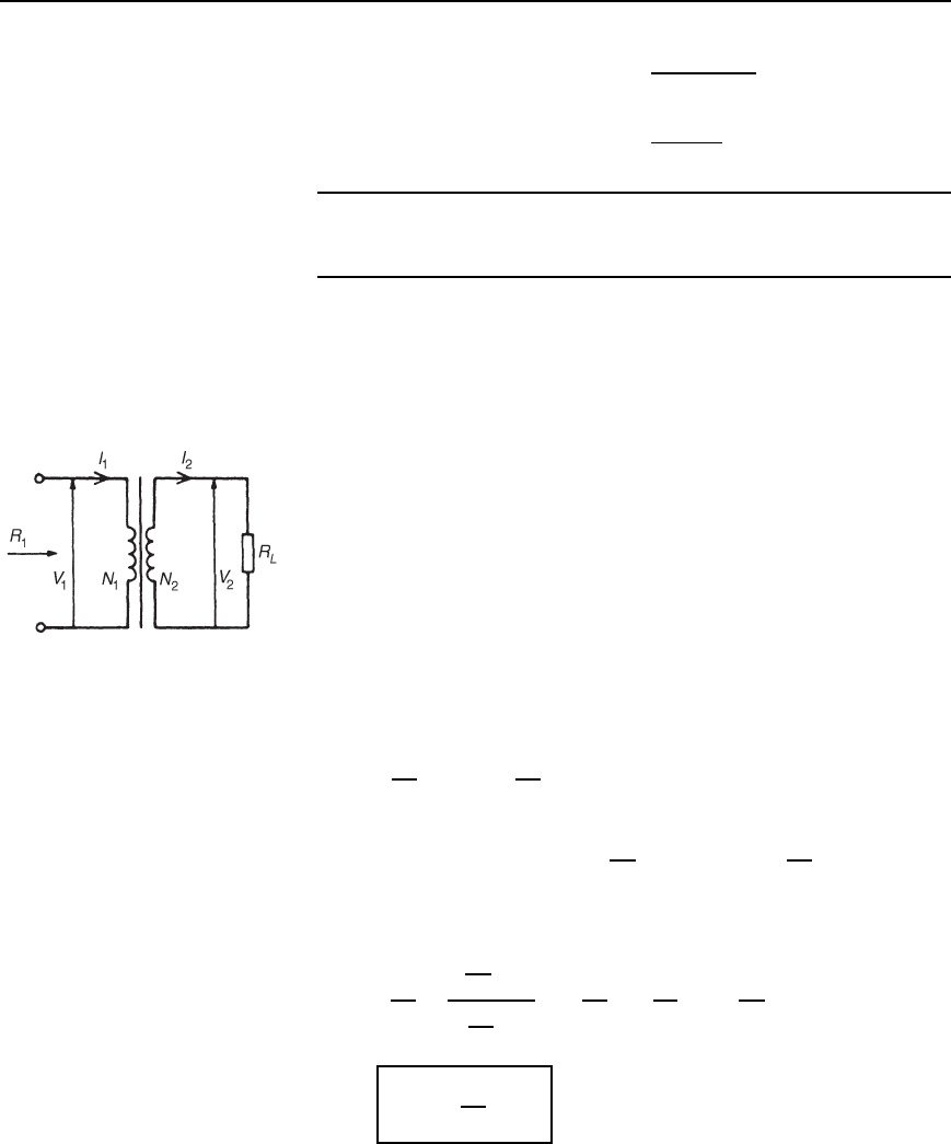
Maximum efficiency, D
1
losses
input power
ð 100%
D
1
5
301.625
ð 100% D 98.34%
Further problems on losses and efficiency may be found in Section 20.16,
problems 21 to 26, page 346.
20.10 Resistance
matching
Varying a load resistance to be equal, or almost equal, to the source
internal resistance is called matching. Examples where resistance match-
ing is important include coupling an aerial to a transmitter or receiver, or
in coupling a loudspeaker to an amplifier, where coupling transformers
may be used to give maximum power transfer.
With d.c. generators or secondary cells, the internal resistance is usually
very small. In such cases, if an attempt is made to make the load resis-
tance as small as the source internal resistance, overloading of the source
results.
A method of achieving maximum power transfer between a source and
a load (see Section 13.9, page 187), is to adjust the value of the load
resistance to ‘match’ the source internal resistance. A transformer may be
used as a resistance matching device by connecting it between the load
and the source.
Figure 20.10
The reason why a transformer can be used for this is shown below.
With reference to Figure 20.10:
R
L
D
V
2
I
2
and R
1
D
V
1
I
1
For an ideal transformer, V
1
D
N
1
N
2
V
2
and I
1
D
N
2
N
1
I
2
Thus the equivalent input resistance R
1
of the transformer is given by:
R
1
D
V
1
I
1
D
N
1
N
2
V
2
N
2
N
1
I
2
D
N
1
N
2
2
V
2
I
2
D
N
1
N
2
2
R
L
i.e.,
R
1
=
N
1
N
2
2
R
L
Hence by varying the value of the turns ratio, the equivalent input resis-
tance of a transformer can be ‘matched’ to the internal resistance of a
load to achieve maximum power transfer.
Transformers 335
Problem 20. A transformer having a turns ratio of 4:1 supplies a
load of resistance 100 . Determine the equivalent input resistance
of the transformer.
From above, the equivalent input resistance,
R
1
D
N
1
N
2
2
R
L
D
4
1
2
100 D 1600 Z
Problem 21. The output stage of an amplifier has an output resis-
tance of 112 . Calculate the optimum turns ratio of a transformer
which would match a load resistance of 7 to the output resistance
of the amplifier.
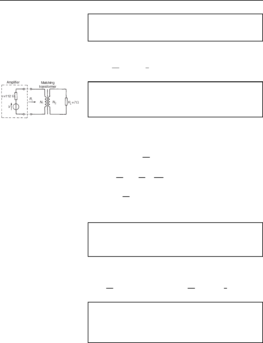
The circuit is shown in Figure 20.11.
Figure 20.11
The equivalent input resistance, R
1
of the transformer needs to be 112
for maximum power transfer.
R
1
D
N
1
N
2
2
R
L
Hence
N
1
N
2
2
D
R
1
R
L
D
112
7
D 16
i.e.,
N
1
N
2
D
p
16 D 4
Hence the optimum turns ratio is 4:1
Problem 22. Determine the optimum value of load resistance for
maximum power transfer if the load is connected to an amplifier
of output resistance 150 through a transformer with a turns ratio
of 5:1.
The equivalent input resistance R
1
of the transformer needs to be 150
for maximum power transfer.
R
1
D
N
1
N
2
2
R
L
, from which, R
L
D R
1
N
2
N
1
2
D 150
1
5
2
D 6 Z
Problem 23. A single-phase, 220 V/1760 V ideal transformer is
supplied from a 220 V source through a cable of resistance 2 .If
the load across the secondary winding is 1.28 k determine (a) the
primary current flowing and (b) the power dissipated in the load
resistor.
