Bird J. Electrical Circuit Theory and Technology
Подождите немного. Документ загружается.

316 Electrical Circuit Theory and Technology
Transformers range in size from the miniature units used in electronic
applications to the large power transformers used in power stations. The
principle of operation is the same for each.
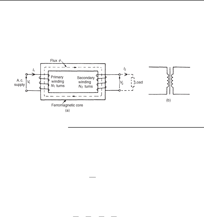
A transformer is represented in Figure 20.1(a) as consisting of two elec-
trical circuits linked by a common ferromagnetic core. One coil is termed
the primary winding which is connected to the supply of electricity, and
the other the secondary winding, which may be connected to a load. A
circuit diagram symbol for a transformer is shown in Figure 20.1(b).
Figure 20.1
20.2 Transformer
principle of operation
When the secondary is an open-circuit and an alternating voltage V
1
is applied to the primary winding, a small current—called the no-load
current I
0
—flows, which sets up a magnetic flux in the core. This alter-
nating flux links with both primary and secondary coils and induces in
them e.m.f.’s of E
1
and E
2
respectively by mutual induction.
The induced e.m.f. E in a coil of N turns is given by
E DN
d
dt
volts,
where d/dt is the rate of change of flux. In an ideal transformer, the
rate of change of flux is the same for both primary and secondary and
thus E
1
/N
1
D E
2
/N
2
,i.e.the induced e.m.f. per turn is constant.
Assuming no losses, E
1
D V
1
and E
2
D V
2
Hence
V
1
N
1
D
V
2
N
2
or
V
1
V
2
D
N
1
N
2
20.1
V
1
/V
2
is called the voltage ratio and N
1
/N
2
the turns ratio, or the ‘trans-
formation ratio’ of the transformer. If N
2
is less than N
1
then V
2
is less
than V
1
and the device is termed a step-down transformer.IfN
2
is
greater then N
1
then V
2
is greater than V
1
and the device is termed a
step-up transformer.
When a load is connected across the secondary winding, a current I
2
flows. In an ideal transformer losses are neglected and a transformer is
considered to be 100% efficient.

Transformers 317
Hence input power D output power, or V
1
I
1
D V
2
I
2
, i.e., in an ideal
transformer, the primary and secondary volt-amperes are equal.
Thus
V
1
V
2
D
I
2
I
1
20.2
Combining equations (20.1) and (20.2) gives:
V
1
V
2
=
N
1
N
2
=
I
2
I
1
20.3
The rating of a transformer is stated in terms of the volt-amperes that
it can transform without overheating. With reference to Figure 20.1(a),
the transformer rating is either V
1
I
1
or V
2
I
2
, where I
2
is the full-load
secondary current.
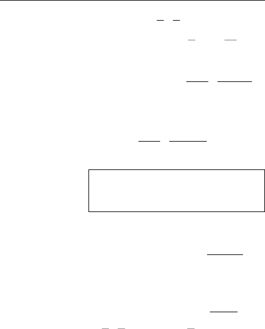
Problem 1. A transformer has 500 primary turns and 3000
secondary turns. If the primary voltage is 240 V, determine the
secondary voltage, assuming an ideal transformer.
For an ideal transformer, voltage ratio D turns ratio i.e.,
V
1
V
2
D
N
1
N
2
, hence
240
V
2
D
500
3000
Thus secondary voltage V
2
D
3000240
500
D 1440 V or 1.44 kV
Problem 2. An ideal transformer with a turns ratio of 2:7 is fed
from a 240 V supply. Determine its output voltage.
A turns ratio of 2:7 means that the transformer has 2 turns on the primary
for every 7 turns on the secondary (i.e. a step-up transformer). Thus,
N
1
N
2
D
2
7
For an ideal transformer,
N
1
N
2
D
V
1
V
2
; hence
2
7
D
240
V
2
Thus the secondary voltage V
2
D
2407
2
D 840 V
Problem 3. An ideal transformer has a turns ratio of 8:1 and the
primary current i
s 3 A when it is supplied at 240 V. Calculate the
secondary voltage and current.
318 Electrical Circuit Theory and Technology
A turns ratio of 8:1 means
N
1
N
2
D
8
1
, i.e. a step-down transformer.
N
1
N
2
D
V
1
V
2
, or secondary voltage V
2
D V
1
N
2
N
1
D 240
1
8
D 30 volts
Also,
N
1
N
2
D
I
2
I
1
I hence secondary current I
2
D I
1
N
1
N
2
D 3
8
1
D 24 A
Problem 4. An ideal transformer, connected to a 240 V mains,
supplies a 12 V, 150 W lamp. Calculate the transformer turns ratio
and the current taken from the supply.
V
1
D 240 V, V
2
D 12 V, I
2
D
P
V
2
D
150
12
D 12.5A
Turns ratio D
N
1
N
2
D
V
1
V
2
D
240
12
D 20
V
1
V
2
D
I
2
I
1
, from which, I
1
D I
2
V
2
V
1
D 12.5
12
240
Hence current taken from the supply, I
1
D
12.5
20
D 0.625 A
Problem 5. A 5 kVA single-phase transformer has a turns ratio of
10:1 and is fed from a 2.5 kV supply. Neglecting losses, determine
(a) the full-load secondary current, (b) the minimum load resistance
which can be connected across the secondary winding to give full
load kVA, (c) the primary current at full load kVA.
(a)
N
1
N
2
D
10
1
and V
1
D 2.5kVD 2500 V
Since
N
1
N
2
D
V
1
V
2
, secondary voltage V
2
D V
1
N
2
N
1
D 2500
1
10
D 250 V
The transformer rating in volt-amperes D V
2
I
2
(at full load),
i.e., 5000 D 250I
2
Transformers 319
Hence full load secondary current I
2
D
5000
250
D 20 A
(b) Minimum value of load resistance, R
L
D
V
2
I
2
D
250
20
D 12.5 Z
(c)
N
1
N
2
D
I
2
I
1
, from which primary current I
1
D I
2
N
2
N
1
D 20
1
10
D 2A
Further problems on the transformer principle of operation may be found
in Section 20.16, problems 1 to 9, page 344.
20.3 Transformer
no-load phasor diagram
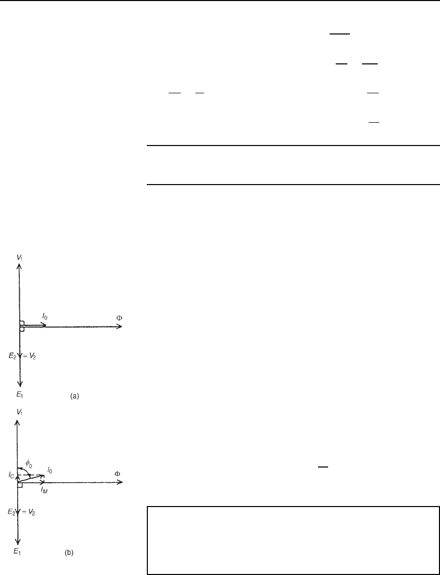
(i) The core flux is common to both primary and secondary windings in
a transformer and is thus taken as the reference phasor in a phasor
diagram. On no-load the primary winding takes a small no-load
current I
0
and since, with losses neglected, the primary winding is
a pure inductor, this current lags the applied voltage V
1
by 90
°
.In
the phasor diagram assuming no losses, shown in Figure 20.2(a),
current I
0
produces the flux and is drawn in phase with the flux.
The primary induced e.m.f. E
1
is in phase opposition to V
1
(by
Lenz’s law) and is shown 180
°
out of phase with V
1
and equal in
magnitude. The secondary induced e.m.f. is shown for a 2:1 turns
ratio transformer.
(ii) A no-load phasor diagram for a practical transformer is shown in
Figure 20.2(b). If current flows then losses will occur. When losses
are considered then the no-load current I
0
is the phasor sum of
two components—(i) I
M
, the magnetizing component, in phase
with the flux, and (ii) I
C
, the core loss component (supplying the
hysteresis and eddy current losses). From Figure 20.2(b):
No-load current, I
0
=
.I
2
M
Y I
2
C
/, where I
M
= I
0
sinf
0
and
I
C
= I
0
cosf
0
Power factor on no-load D cos
0
D
I
C
I
0
The total core losses (i.e. iron losses) D V
1
I
0
cos
0
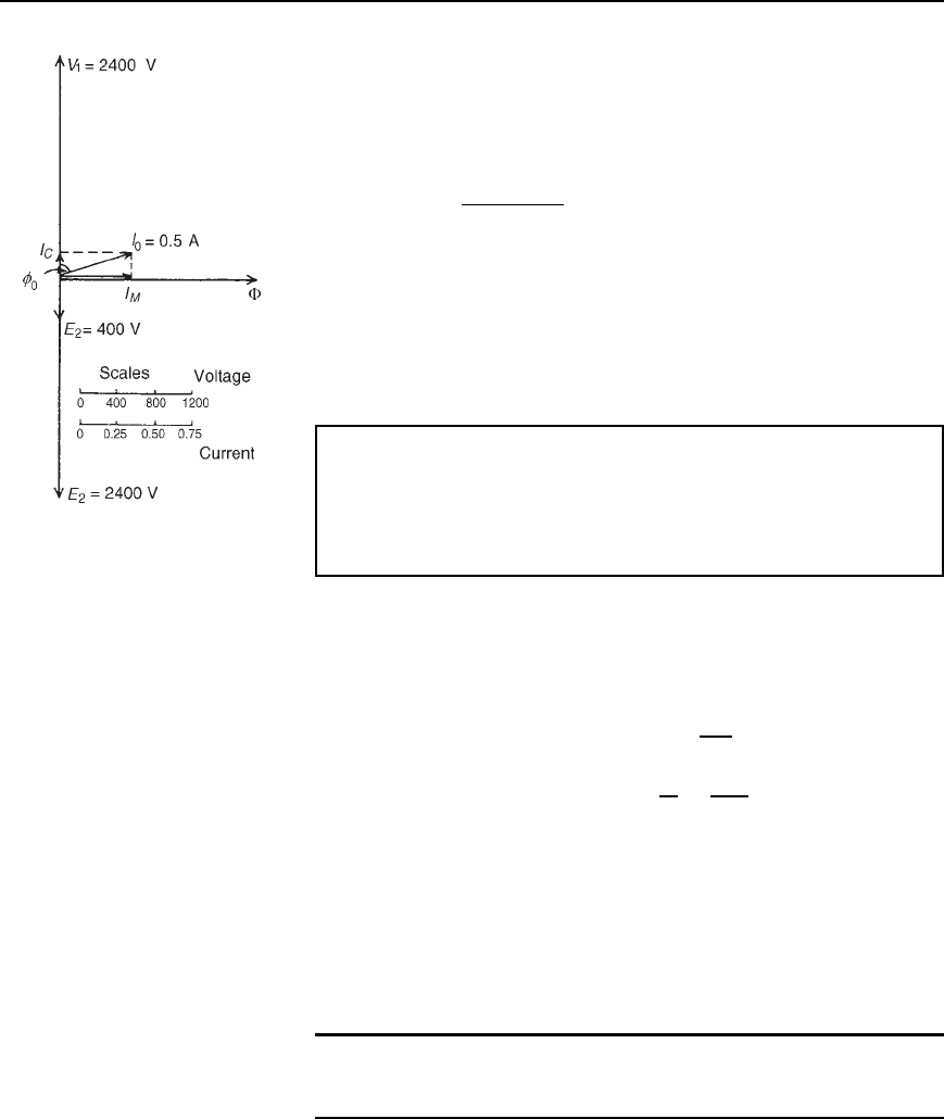
Problem 6. A 2400 V/400 V single-phase transformer takes a no-
load current of 0.5 A and the core loss is 400 W. Determine the
values of the magnetizing and core loss components of the no-
load current. Draw to scale the no-load phasor diagram for the
transformer.
Figure 20.2
320 Electrical Circuit Theory and Technology
Figure 20.3
V
1
D 2400 V, V
2
D 400 V, I
0
D 0.5A
Core loss (i.e. iron loss) D 400 D V
1
I
0
cos
0
i.e. 400 D 24000.5 cos
0
Hence cos
0
D
400
24000.5
D 0.3333
0
D arccos0.3333 D 70.53
°
The no-load phasor diagram is shown in Figure 20.3.
Magnetizing component, I
M
D I
0
sin
0
D 0.5sin70.53
°
D 0.471 A
Core loss component, I
C
D I
0
cos
0
D 0.5cos70.53
°
D 0.167 A
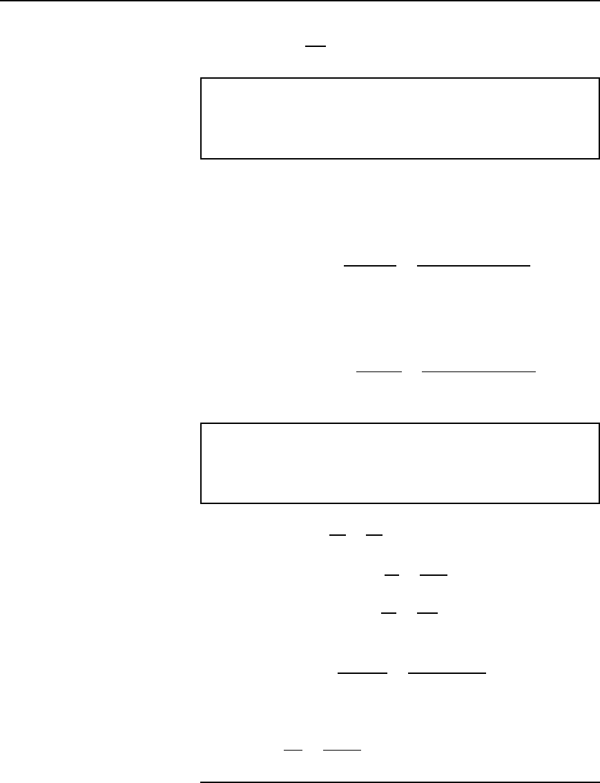
Problem 7. A transformer takes a current of 0.8 A when its
primary is connected to a 240 volt, 50 Hz supply, the secondary
being on open circuit. If the power absorbed is 72 watts, determine
(a) the iron loss current, (b) the power factor on no-load, and (c) the
magnetizing current.
I
0
D 0.8A,V D 240 V
(a) Power absorbed D total core loss D 72 D V
1
I
0
cos
0
Hence 72 D 240 I
0
cos
0
and iron loss current, I
c
D I
0
cos
0
D
72
240
D 0.30 A
(b) Power factor at no load, cos
0
D
I
c
I
0
D
0.30
0.80
D 0.375
(c) From the right-angled triangle in Figure 20.2(b) and using
Pythagoras’ theorem, I
2
0
D I
2
c
C I
2
M
from which, magnetizing current, I
M
D
I
2
0
I
2
c
D
0.80
2
0.30
2
D 0.74 A
Further problems on the no-load phasor diagram may be found in
Section 20.16, problems 10 to 12, page 344.
20.4 E.m.f. equation of a
transformer
The magnetic flux set up in the core of a transformer when an alter-
nating voltage is applied to its primary winding is also alternating and is
sinusoidal.

Transformers 321
Let
m
be the maximum value of the flux and f be the frequency of
the supply. The time for 1 cycle of the alternating flux is the periodic
time T, where T D 1/f seconds
The flux rises sinusoidally from zero to its maximum value in
1
4
cycle,
and the time for
1
4
cycle is 1/4f seconds.
Hence the average rate of change of flux D
m
1/4f
D 4f
m
Wb/s,
and since 1 Wb/s D 1 volt, the average e.m.f. induced in each turn
D 4f
m
volts.
As the flux varies sinusoidally, then a sinusoidal e.m.f. will be
induced in each turn of both primary and secondary windings.
For a sine wave, form factor D
rms value
average value
D 1.11 (see Chapter 14)
Hence rms value D form factor ð average value
D 1.11 ð average value
Thus rms e.m.f. induced in each turn D 1.11 ð4f
m
volts
D 4.44f
m
volts
Therefore, rms value of e.m.f. induced in primary,
E
1
= 4.44f 8
m
N
1
volts 20.4
and rms value of e.m.f. induced in secondary,
E
2
= 4.44f 8
m
N
2
volts 20.5
Dividing equation (20.4) by equation (20.5) gives:
E
1
E
2
D
N
1
N
2
, as previously obtained in Section 20.2.
Problem 8. A 100 kVA, 4000 V/200 V, 50 Hz single-phase trans-
former has 100 secondary turns. Determine (a) the primary and
secondary current, (b) the number of primary turns, and (c) the
maximum value of the flux.
V
1
D 4000 V, V
2
D 200 V, f D 50 Hz, N
2
D 100 turns
(a) Transformer rating D V
1
I
1
D V
2
I
2
D 100000 VA
Hence primary current, I
1
D
100000
V
1
D
100000
4000
D 25 A
and secondary current, I
2
D
100000
V
2
D
100000
200
D 500 A
322 Electrical Circuit Theory and Technology
(b) From equation (20.3),
V
1
V
2
D
N
1
N
2
from which, primary turns, N
1
D
V
1
V
2
N
2
D
4000
200
100
i.e., N
1
= 2000 turns
(c) From equation (20.5), E
2
D 4.44f
m
N
2
from which, maximum flux
m
D
E
2
4.44fN
2
D
200
4.4450100
(assuming E
2
D V
2
)
D 9.01
× 10
−3
Wb or 9.01 mWb
[Alternatively, equation (20.4) could have been used,
where E
1
D 4.44f
m
N
1
from which,
m
D
E
1
4.44fN
1
D
4000
4.44502000
(assuming E
1
D V
1
D 9.01 mWb, as above]
Problem 9. A single-phase, 50 Hz transformer has 25 primary
turns and 300 secondary turns. The cross-sectional area of the core
is 300 cm
2
. When the primary winding is connected to a 250 V
supply, determine (a) the maximum value of the flux density in the
core, and (b) the voltage induced in the secondary winding.
(a) From equation (20.4), e.m.f. E
1
D 4.44f
m
N
1
volts i.e.,
250 D 4.4450
m
25
from which, maximum flux density,
m
D
250
4.445025
Wb
D 0.04505 Wb
However,
m
D B
m
ð A, where B
m
D maximum flux density in the
core and A D cross-sectional area of the core (see Chapter 7)
Hence B
m
ð 300 ð10
4
D 0.04505
from which, maximum flux density, B
m
D
0.04505
300 ð 10
4
D 1.50 T
(b)
V
1
V
2
D
N
1
N
2
, from which, V
2
D V
1
N
2
N
1
i.e., voltage induced in the secondary winding,
Transformers 323
V
2
D 250
300
25
D 3000 V or 3 kV
Problem 10. A single-phase 500 V/100 V, 50 Hz transformer has
a maximum core flux density of 1.5 T and an effective core cross-
sectional area of 50 cm
2
. Determine the number of primary and
secondary turns.
The e.m.f. equation for a transformer is E D 4.44f
m
N
and maximum flux,
m
D B ð A D 1.550 ð 10
4
D 75 ð 10
4
Wb
Since E
1
D 4.44f
m
N
1
then primary turns, N
1
D
E
1
4.44f
m
D
500
4.445075 ð 10
4
D 300 turns
Since E
2
D 4.4f
m
N
2
then secondary turns, N
2
D
E
2
4.4f
m
D
100
4.445075 ð 10
4
D 60 turns
Problem 11. A 4500 V/225 V, 50 Hz single-phase transformer is
to have an approximate e.m.f. per turn of 15 V and operate with a
maximum flux of 1.4 T. Calculate (a) the number of primary and
secondary turns and (b) the cross-sectional area of the core.
(a) E.m.f. per turn D
E
1
N
1
D
E
2
N
2
D 15
Hence primary turns, N
1
D
E
1
15
D
4500
15
D 300
and secondary turns, N
2
D
E
2
15
D
225
15
D 15
(b) E.m.f. E
1
D 4.44f
m
N
1
from which,
m
D
E
1
4.44fN
1
D
4500
4.4450300
D 0.0676 Wb
Now flux
m
D B
m
ð A, where A is the cross-sectional area of the
core, hence
area A D
m
B
m
D
0.0676
1.4
D 0.0483 m
2
or 483 cm
2
324 Electrical Circuit Theory and Technology
Further problems on the e.m.f. equation may be found in Section 20.16,
problems 13 to 16, page 345.
20.5 Transformer
on-load phasor diagram
If the voltage drop in the windings of a transformer are assumed negli-
gible, then the terminal voltage V
2
is the same as the induced e.m.f. E
2
in
the secondary. Similarly, V
1
D E
1
. Assuming an equal number of turns
on primary and secondary windings, then E
1
D E
2
, and let the load have
a lagging phase angle
2
.
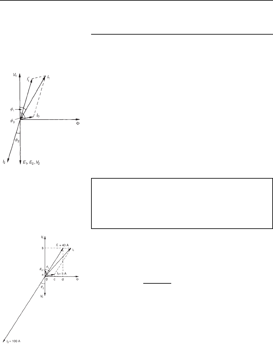
In the phasor diagram of Figure 20.4, current I
2
lags V
2
by angle
2
.
When a load is connected across the secondary winding a current I
2
flows
in the secondary winding. The resulting secondary e.m.f. acts so as to tend
to reduce the core flux. However this does not happen since reduction of
the core flux reduces E
1
, hence a reflected increase in primary current I
0
1
occurs which provides a restoring mmf. Hence at all loads, primary and
secondary mmf’s are equal, but in opposition, and the core flux remains
constant. I
0
1
is sometimes called the ‘balancing’ current and is equal, but
in the opposite direction, to current I
2
as shown in Figure 20.4. I
0
, shown
at a phase angle
0
to V
1
, is the no-load current of the transformer (see
Section 20.3).
The phasor sum of I
0
1
and I
0
gives the supply current I
1
and the phase
angle between V
1
and I
1
is shown as
1
.
Figure 20.4
Problem 12. A single-phase transformer has 2000 turns on the
primary and 800 turns on the secondary. Its no-load current is 5 A
at a power factor of 0.20 lagging. Assuming the volt drop in the
windings is negligible, determine the primary current and power
factor when the secondary current is 100 A at a power factor of
0.85 lagging.
Let I
0
1
be the component of the primary current which provides the
restoring mmf. Then
I
0
1
N
1
D I
2
N
2
i.e., I
0
1
2000 D 100800
from which, I
0
1
D
100800
2000
D 40 A
If the power factor of the secondary is 0.85
then cos
2
D 0.85, from which,
2
D arccos0.85 D 31.8
°
If the power factor on no-load is 0.20,
then cos
0
D 0.2and
0
D arccos0.2 D 78.5
°
In the phasor diagram shown in Figure 20.5, I
2
D 100 A is shown at an
angle of
2
D 31.8
°
to V
2
and I
0
1
D 40 A is shown in anti-phase to I
2
.
Figure 20.5
Transformers 325
The no-load current I
0
D 5 A is shown at an angle of
0
D 78.5
°
to V
1
.
Current I
1
is the phasor sum of I
0
1
and I
0
and by drawing to scale,
I
1
D 44 A and angle
1
D 37
°
By calculation, I
1
cos
1
D oa C ob
D I
0
cos
0
C I
0
1
cos
2
D 50.2 C 400.85
D 35.0A
and I
1
sin
1
D oc C od
D I
0
sin
0
C I
0
1
sin
2
D 5 sin 78.5
°
C 40 sin31.8
°
D 25.98 A
Hence the magnitude of I
1
D
p
35.0
2
C 25.98
2
D 43.59 A
and tan
1
D
25.98
35.0
, from which,
1
D arctan
25.98
35.0
D 36.59
°
Hence the power factor of the primary D cos
1
D cos36.59
°
D 0.80
A further problem on the transformer on-load may be found in
Section 20.16, problem 17, page 345.
20.6 Transformer
construction
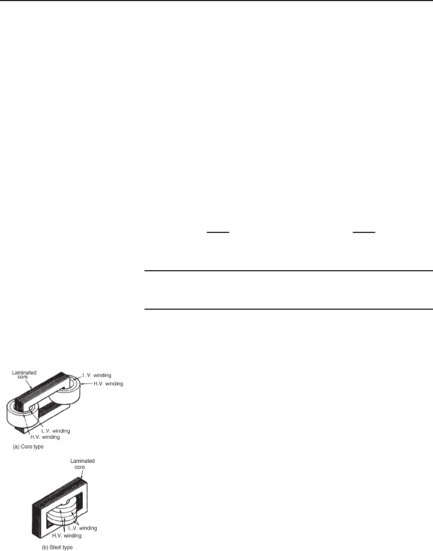
(i) There are broadly two types of single-phase double-wound trans-
former constructions— the core type and the shell type, as shown
in Figure 20.6. The low and high voltage windings are wound as
shown to reduce leakage flux.
(ii) For power transformers, rated possibly at several MVA and
operating at a frequency of 50 Hz in Great Britain, the core material
used is usually laminated silicon steel or stalloy, the laminations
reducing eddy currents and the silicon steel keeping hysteresis loss
to a minimum.
Large power transformers are used in the main distribution
system and in industrial supply circuits. Small power transformers
have many applications, examples including welding and rectifier
supplies, domestic bell circuits, imported washing machines, and
so on.
(iii) For audio frequency (a.f.) transformers, rated from a few mVA
to no more than 20 VA, and operating at frequencies up to about
15 kHz, the small core is also made of laminated silicon steel.
A typical application of a.f. transformers is in an audio amplifier
system.
Figure 20.6
