Bird J. Electrical Circuit Theory and Technology
Подождите немного. Документ загружается.


286 Electrical Circuit Theory and Technology
Problem 7. For the op amp shown in Figure 18.8, R
1
D 4.7k
and R
2
D 10 k. If the input voltage is 0.4 V, determine (a) the
voltage gain (b) the output voltage
Input voltage
R
1
Output
voltage
0V
R
2
−
+
Figure 18.8
The op amp shown in Figure 18.8 is a non-inverting amplifier, similar to
Figure 18.7.
(a) From equation (7), voltage gain,
A D 1 C
R
f
R
i
D 1 C
R
2
R
1
D 1 C
10 ð 10
3
4.7 ð 10
3
D 1 C2.13 D 3.13
(b) Also from equation (7), output voltage,
V
o
D
1 C
R
R
1
V
i
D 3.130.4 D −1.25 V
18.5 Op amp
voltage-follower
The voltage-follower is a special case of the non-inverting amplifier
in which 100% negative feedback is obtained by connecting the output
directly to the inverting () terminal, as shown in Figure 18.9. Thus R
f
in Figure 18.7 is zero and R
i
is infinite.
−
+
V
o
V
i
0V
Figure 18.9
From equation (6), A D 1/ˇ (when A
o
is very large). Since all of the
output is fed back, ˇ D 1andA ³ 1. Thus the voltage gain is nearly 1
and V
o
D V
i
to within a few millivolts.
The circuit of Figure 18.9 is called a voltage-follower since, as with its
transistor emitter-follower equivalent, V
o
follows V
i
. It has an extremely
high input impedance and a low output impedance. Its main use is as a
buffer amplifier, giving current amplification, to match a high impedance
source to a low impedance load. For example, it is used as the input stage
of an analogue voltmeter where the highest possible input impedance is
required so as not to disturb the circuit under test; the output voltage is
measured by a relatively low impedance moving-coil meter.
18.6 Op amp summing
amplifier
Because of the existence of the virtual earth point, an op amp can be used
to add a number of voltages (d.c. or a.c.) when connected as a multi-input
inverting amplifier. This, in turn, is a consequence of the high value of
the open-loop voltage gain A
o
. Such circuits may be used as ‘mixers’ in
audio systems to combine the outputs of microphones, electric guitars,
pick-ups, etc. They are also used to perform the mathematical process of
addition in analogue computing.
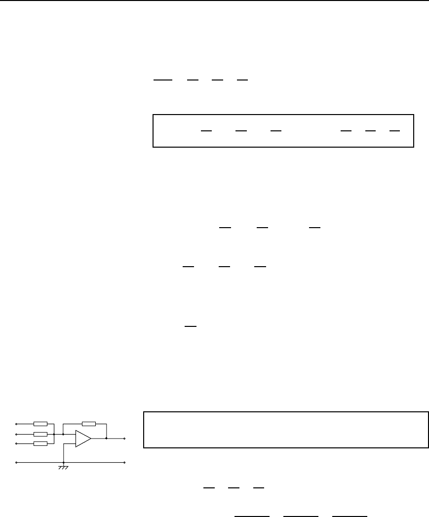
The circuit of an op amp summing amplifier having three input voltages
V
1
, V
2
and V
3
applied via input resistors R
1
, R
2
and R
3
is shown in
Figure 18.10. If it is assumed that the inverting () terminal of the op
R
1
R
2
R
3
I
1
I
2
I
3
V
1
V
2
V
3
I
R
f
V
o
0V
−
+
X
Figure 18.10
Operational amplifiers 287
amp draws no input current, all of it passing through R
f
, then:
I D I
1
C I
2
C I
3
Since X is a virtual earth (i.e. at 0 V), it follows that:
V
o
R
f
D
V
1
R
1
C
V
2
R
2
C
V
3
R
3
Hence
V
o
= −
R
f
R
1
V
1
Y
R
f
R
2
V
2
Y
R
f
R
3
V
3
= −R
f
V
1
R
1
Y
V
2
R
2
Y
V
3
R
3
8
The three input voltages are thus added and amplified if R
f
is greater
than each of the input resistors; ‘weighted’ summation is said to have
occurred.
Alternatively, the input voltages are added and attenuated if R
f
is less
than each input resistor.
For example, if
R
f
R
1
D 4,
R
f
R
2
D 3and
R
f
R
3
D 1andV
1
D V
2
D V
3
D
C1V, then
V
o
R
f
R
1
V
1
C
R
f
R
2
V
2
C
R
f
R
3
V
3
D4 C 3 C 1 D −8V
If R
1
D R
2
D R
3
D R
i
, the input voltages are amplified or attenuated
equally, and
V
o
D
R
f
R
i
V
1
C V
2
C V
3
If, also, R
i
D R
f
then V
o
DV
1
C V
2
C V
3
The virtual earth is also called the summing point of the amplifier. It
isolates the inputs from one another so that each behaves as if none of
the others existed and none feeds any of the other inputs even though all
the resistors are connected at the inverting () input.
0.5 V
0.8 V
1.2 V
10 kΩ
50 kΩ
20 kΩ
30 kΩ
V
o
−
+
Figure 18.11
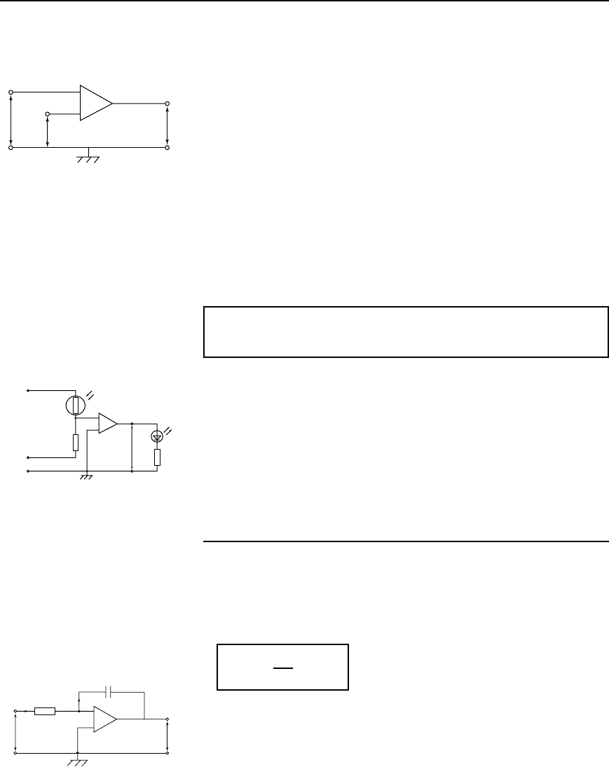
Problem 8. For the summing op amp shown in Figure 18.11, de-
termine the output voltage, V
o
From equation (8),
V
o
DR
f
V
1
R
1
C
V
2
R
2
C
V
3
R
3
D50 ð 10
3
0.5
10 ð 10
3
C
0.8
20 ð 10
3
C
1.2
30 ð 10
3
D50 ð 10
3
5 ð 10
5
C 4 ð 10
5
C 4 ð 10
5
D50 ð 10
3
13 ð 10
5
=−6.5V
288 Electrical Circuit Theory and Technology
18.7 Op amp voltage
comparator
If both inputs of the op amp shown in Figure 18.12 are used simultane-
ously, then from equation (1), page 279, the output voltage is given by:
V
o
D A
o
V
2
V
1
V
1
v
2
V
o
−
+
0V
Figure 18.12
When V
2
>V
1
then V
o
is positive, its maximum value being the positive
supply voltage C V
s
, which it has when V
2
V
1
½ V
s
/A
o
. The op amp
is then saturated. For example, if V
s
DC9VandA
o
D 10
5
, then saturation
occurs when V
2
V
1
½ 9/10
5
i.e. when V
2
exceeds V
1
by 90µVand
V
o
³ 9V.
When V
1
>V
2
, then V
o
is negative and saturation occurs if V
1
exceeds
V
2
by V
s
/A
o
i.e. around 90µV in the above example; in this case, V
o
³
V
s
D9V.
A small change in (V
2
V
1
) therefore causes V
o
to switch between
near CV
s
and near to V
s
and enables the op amp to indicate when V
2
is
greater or less than V
1
, i.e. to act as a differential amplifier and compare
two voltages. It does this in an electronic digital voltmeter.
Problem 9. Devise a light-operated alarm circuit using an op amp,
a LDR, a LED and a š15V supply
A typical light-operated alarm circuit is shown in Figure 18.13.
+15 V
−15 V
0V
LDR
R
V
1
V
2
+
−
V
o
LED
Figure 18.13
Resistor R and the light dependent resistor (LDR) form a voltage divider
across the C15/0/15V supply. The op amp compares the voltage V
1
at the voltage divider junction, i.e. at the inverting () input, with that
at the non-inverting (C) input, i.e. with V
2
, which is 0 V. In the dark
the resistance of the LDR is much greater than that of R, so more of the
30V across the voltage divider is dropped across the LDR, causing V
1
to fall below 0 V. Now V
2
>V
1
and the output voltage V
o
switches
from near 15V to near C15V and the light emitting diode (LED)
lights.
18.8 Op amp integrator
The circuit for the op amp integrator shown in Figure 18.14 is the same
as for the op amp inverting amplifier shown in Figure 18.5, but feedback
occurs via a capacitor C, rather than via a resistor.
The output voltage is given by:
V
o
= −
1
CR
V
i
dt
9
Since the inverting () input is used in Figure 18.15, V
o
is negative if
V
i
is positive, and vice versa, hence the negative sign in equation (9).
Since X is a virtual earth in Figure 18.14, i.e. at 0V, the voltage across
R is V
i
and that across C is V
o
. Assuming again that none of the input
current I enters the op amp inverting () input, then all of current I flows
through C and charges it up. If V
i
is constant, I will be a constant value
V
o
+
−
C
I
I
R
V
i
X
Figure 18.14
Operational amplifiers 289
Saturation
(Just <+9V)
Ramp voltage (+2 V/s)
Time t(s)
012345
2
4
6
8
9
V
o
Figure 18.15
given by I D V
i
/R. Capacitor C therefore charges at a constant rate and
the potential of the output side of C (D V
o
, since its input side is zero)
charges so that the feedback path absorbs I. If Q is the charge on C at
time t and the p.d. across it (i.e. the output voltage) changes from 0 to
V
o
in that time then:
Q DV
o
C D It
(from Chapter 6)
i.e. V
o
C D
V
i
R
t
i.e. V
o
D
1
CR
V
i
t
This result is the same as would be obtained from V
o
D
1
CR
V
i
dt if
V
i
is a constant value.
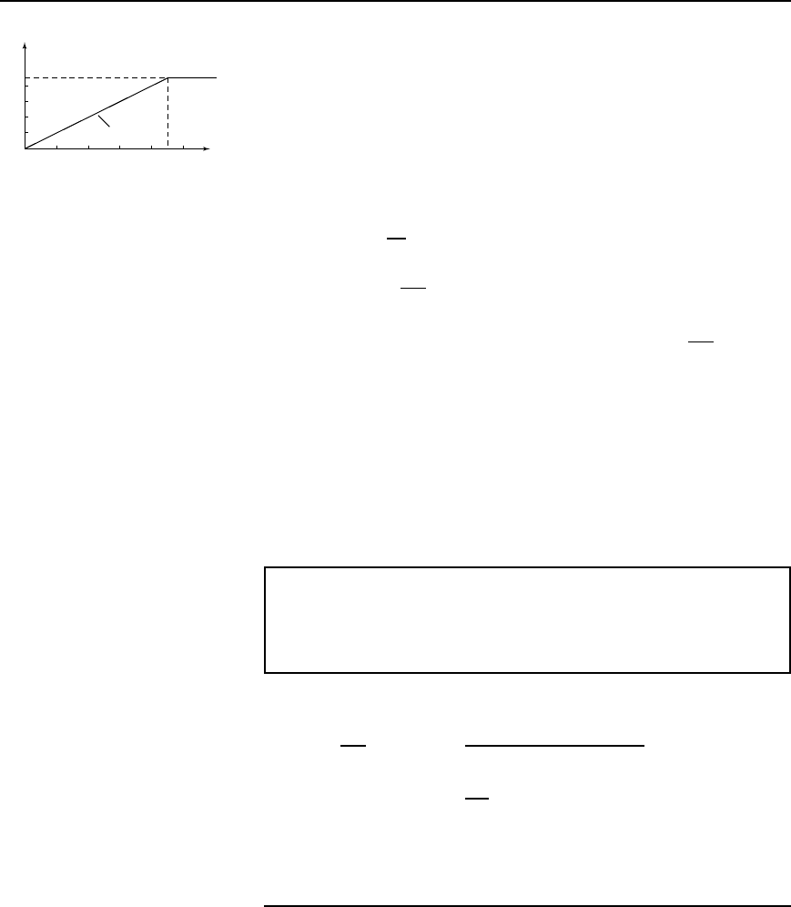
For example, if the input voltage V
i
D2V and, say, CR D 1s, then
V
o
D2t D 2t
A graph of V
o
/t will be a ramp function as shown in Figure 18.15
(V
o
D 2t is of the straight line form y D mx Cc; in this case y D V
o
and
x D t, gradient, m D 2 and vertical axis intercept c D 0). V
o
rises steadily
by C2 V/s in Figure 18.15, and if the power supply is, say, š9 V, then
V
o
reaches C9 V after 4.5 s when the op amp saturates.
Problem 10. A steady voltage of 0.75V is applied to an op amp
integrator having component values of R D 200k and C D 2.5
µF.
Assuming that the initial capacitor charge is zero, determine the
value of the output voltage 100ms after application of the input.
From equation (9), output voltage,
V
o
D
1
CR
V
i
dt D
1
2.5 ð 10
6
200 ð 10
3
0.75 dt
D
1
0.5
0.75 dt D2[0.75t] DC1.5t
When time t D 100 ms, output voltage,
V
o
D 1.5100 ð 10
3
D 0.15V
18.9 Op amp differential
amplifier
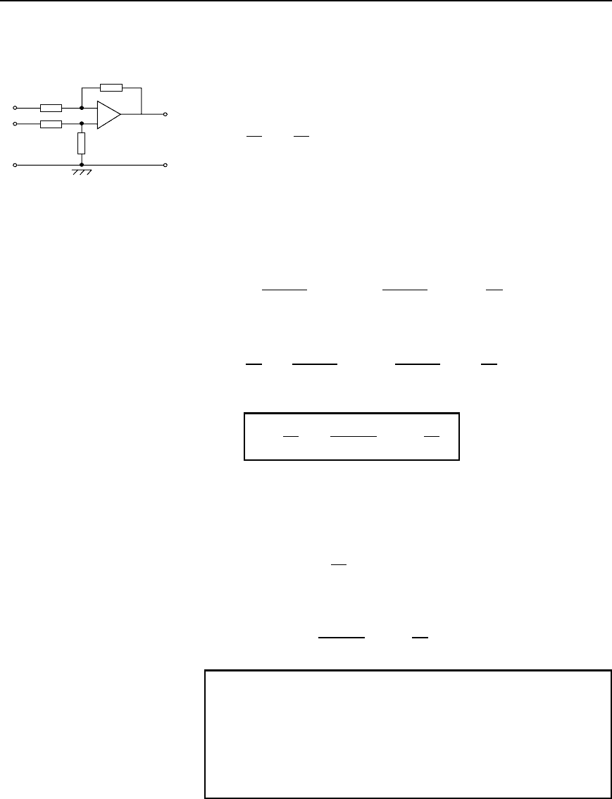
The circuit for an op amp differential amplifier is shown in Figure 18.16
where voltages V
1
and V
2
are applied to its two input terminals and the
difference between these voltages is amplified.
(i) Let V
1
volts be applied to terminal 1 and 0 V be applied to terminal
2. The difference in the potentials at the inverting () and non-inverting
290 Electrical Circuit Theory and Technology
(C) op amp inputs is practically zero and hence the inverting terminal
must be at zero potential. Then I
1
D V
1
/R
1
. Since the op amp input
resistance is high, this current flows through the feedback resistor R
f
.
The volt drop across R
f
, which is the output voltage V
o
D V
1
/R
1
R
f
;
hence, the closed loop voltage gain A is given by:
A D
V
o
V
1
D
R
f
R
1
10
−
+
R
1
R
2
R
3
R
f
V
o
V
1
V
2
1
2
0V
Figure 18.16
(ii) By similar reasoning, if V
2
is applied to terminal 2 and 0V to
terminal 1, then the voltage appearing at the non-inverting terminal will
be R
3
/R
2
C R
3
V
2
volts. This voltage will also appear at the inverting
() terminal and thus the voltage across R
1
is equal to R
3
/R
2
C R
3
V
2
volts.
Now the output voltage,
V
o
D
R
3
R
2
C R
3
V
2
C
R
3
R
2
C R
3
V
2
R
f
R
1
and the voltage gain,
A D
V
o
V
2
D
R
3
R
2
C R
3
C
R
3
R
2
C R
3
R
f
R
1
i.e.
A =
V
o
V
2
=
R
3
R
2
Y R
3
1 Y
R
f
R
1
11
(iii) Finally, if the voltages applied to terminals 1 and 2 are V
1
and
V
2
respectively, then the difference between the two voltages will be
amplified.
If V
1
> V
2
, then:
V
o
= .V
1
− V
2
/
−
R
f
R
1
12
If V
2
> V
1
, then:
V
o
= .V
2
− V
1
/
R
3
R
2
Y R
3
1 Y
R
f
R
1
13
Problem 11. In the differential amplifier shown in Figure 18.16,
R
1
D 10k, R
2
D 10k, R
3
D 100k and R
f
D 100k. Deter-
mine the output voltage V
o
if:
(a) V
1
D 5mVandV
2
D 0
(b) V
1
D 0andV
2
D 5mV
(c) V
1
D 50 mV and V
2
D 25mV
(d) V
1
D 25 mV and V
2
D 50mV

Operational amplifiers 291
(a) From equation (10),
V
o
D
R
f
R
1
V
1
D
100 ð 10
3
10 ð 10
3
5 mV D −50mV
(b) From equation (11),
V
o
D
R
3
R
2
C R
3
1 C
R
f
R
1
V
2
D
100
110
1 C
100
10
5 mV D Y50mV
(c) V
1
>V
2
hence from equation (12),
V
o
D V
1
V
2
R
f
R
1
D 50 25
100
10
mV D −250mV
(d) V
2
>V
1
hence from equation (13),
V
o
D V
2
V
1
R
3
R
2
C R
3
1 C
R
f
R
1
D 50 25 mV
100
100 C 10
1 C
100
10
mV
D 25
100
110
11 D Y250 mV
Further problems on operational amplifier calculations may be found in
Section 18.12, problems 7 to 11, page 295.
18.10 Digital to analogue
(D/A) conversion
There are a number of situations when digital signals have to be converted
to analogue ones. For example, a digital computer often needs to produce
a graphical display on the screen; this involves using a D/A converter
to change the two-level digital output voltage from the computer, into a
continuously varying analogue voltage for the input to the cathode ray
tube, so that it can deflect the electron beam to produce screen graphics.
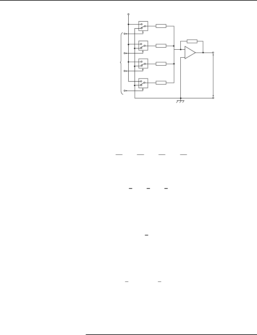
A binary weighted resistor D/A converter is shown in Figure 18.17
for a four-bit input. The values of the resistors, R,2R,4R,8R increase
according to the binary scale—hence the name of the converter. The
circuit uses an op amp as a summing amplifier (see section 18.6) with a
feedback resistor R
f
. Digitally controlled electronic switches are shown
as S
1
to S
4
. Each switch connects the resistor in series with it to a fixed
reference voltage V
ref
when the input bit controlling it is a 1 and to ground
(0V) when it is a 0. The input voltages V
1
to V
4
applied to the op amp
by the four-bit input via the resistors therefore have one of two values,
i.e. either V
ref
or 0 V.
292 Electrical Circuit Theory and Technology
1
0
1
0
1
0
1
0
S
1
S
2
S
3
S
4
V
1
V
2
V
3
V
4
R
2
R
R
f
Analogue
voltage
output
V
o
4-bit
digital
input
V
ref
m.s.b.
i.s.b.
4
R
8
R
0V
−
+
Figure 18.17
From equation (8), page 287, the analogue output voltage V
o
is
given by:
V
o
D
R
f
R
V
1
C
R
f
2R
V
2
C
R
f
4R
V
3
C
R
f
8R
V
4
Let R
f
D R D 1k, then:
V
o
D
V
1
C
1
2
V
2
C
1
4
V
3
C
1
8
V
4
With a four-bit input of 0001 (i.e. decimal 1), S
4
connects 8R to V
ref
,
i.e. V
4
D V
ref
,andS
1
, S
2
and S
3
connect R,2R and 4R to 0V, making
V
1
D V
2
D V
3
D 0. Let V
ref
D8V, then output voltage,
V
o
D
0 C 0 C 0 C
1
8
8
D Y1V
With a four-bit input of 0101 (i.e. decimal 5), S
2
and S
4
connects 2R
and 4R to V
ref
,i.e.V
2
D V
4
D V
ref
,andS
1
and S
3
connect R and 4R to
0V, making V
1
D V
3
D 0. Again, if V
ref
D8V, then output voltage,
V
o
D
0 C
1
2
8 C 0 C
1
8
8
D Y5V
If the input is 0111 (i.e. decimal 7), the output voltage will be 7V, and
so on. From these examples, it is seen that the analogue output voltage,
V
o
, is directly proportional to the digital input.
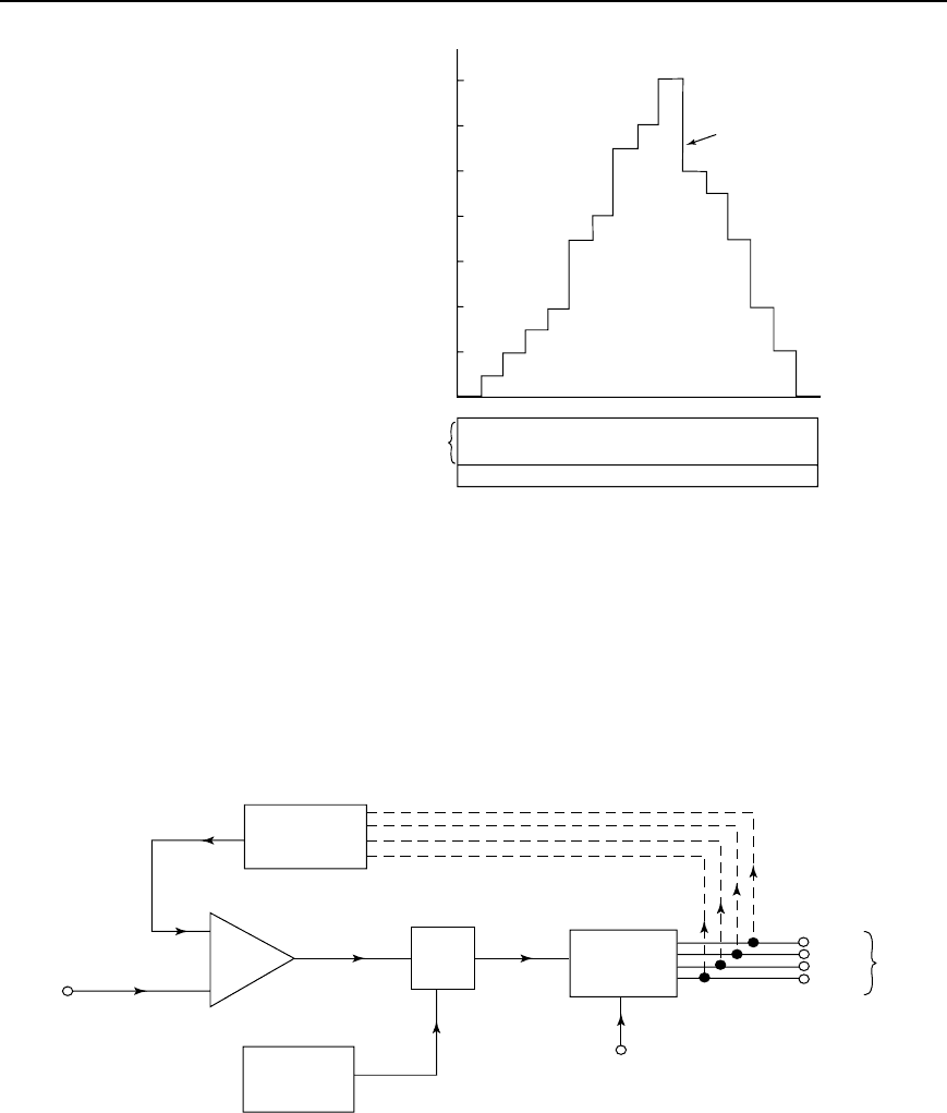
V
o
has a ‘stepped’ waveform, the waveform shape depending on the
binary input. A typical waveform is shown in Figure 18.18.
Operational amplifiers 293
0 0000
1 0001
2 0010
3 0011
4 0100
7 0111
8 1000
11 1011
12 1100
14 1110
10 1010
9 1001
7 0111
4 0100
2 0010
0 0000
Binary
input
Decimal
l.s.b.
m.s.b.
0
2
4
6
8
10
12
14
V
o
Analogue
output
voltage
Figure 18.18
18.11 Analogue to digital
(A/D) conversion
In a digital voltmeter, its input is in analogue form and the reading is
displayed digitally. This is an example where an analogue to digital
converter is needed.
A block diagram for a four-bit counter type A/D conversion circuit is
shown in Figure 18.19. An op amp is again used, in this case as a voltage
comparator (see Section 18.7). The analogue input voltage V
2
, shown
in Figure 18.20(a) as a steady d.c. voltage, is applied to the non-inverting
(C) input, whilst a sawtooth voltage V
1
supplies the inverting () input.
V
1
V
2
−
+
Binary
counter
Analogue input
voltage
AND
gate
Ramp
generator
(D/A convertor)
Pulse
generator
(clock)
Voltage
comparator
Reset
m.s.b
l.s.b
4-bit
digital
output
Figure 18.19
The output from the comparator is applied to one input of an AND
gate and is a 1 (i.e. ‘high’) until V
1
equals or exceeds V
2
, when it then
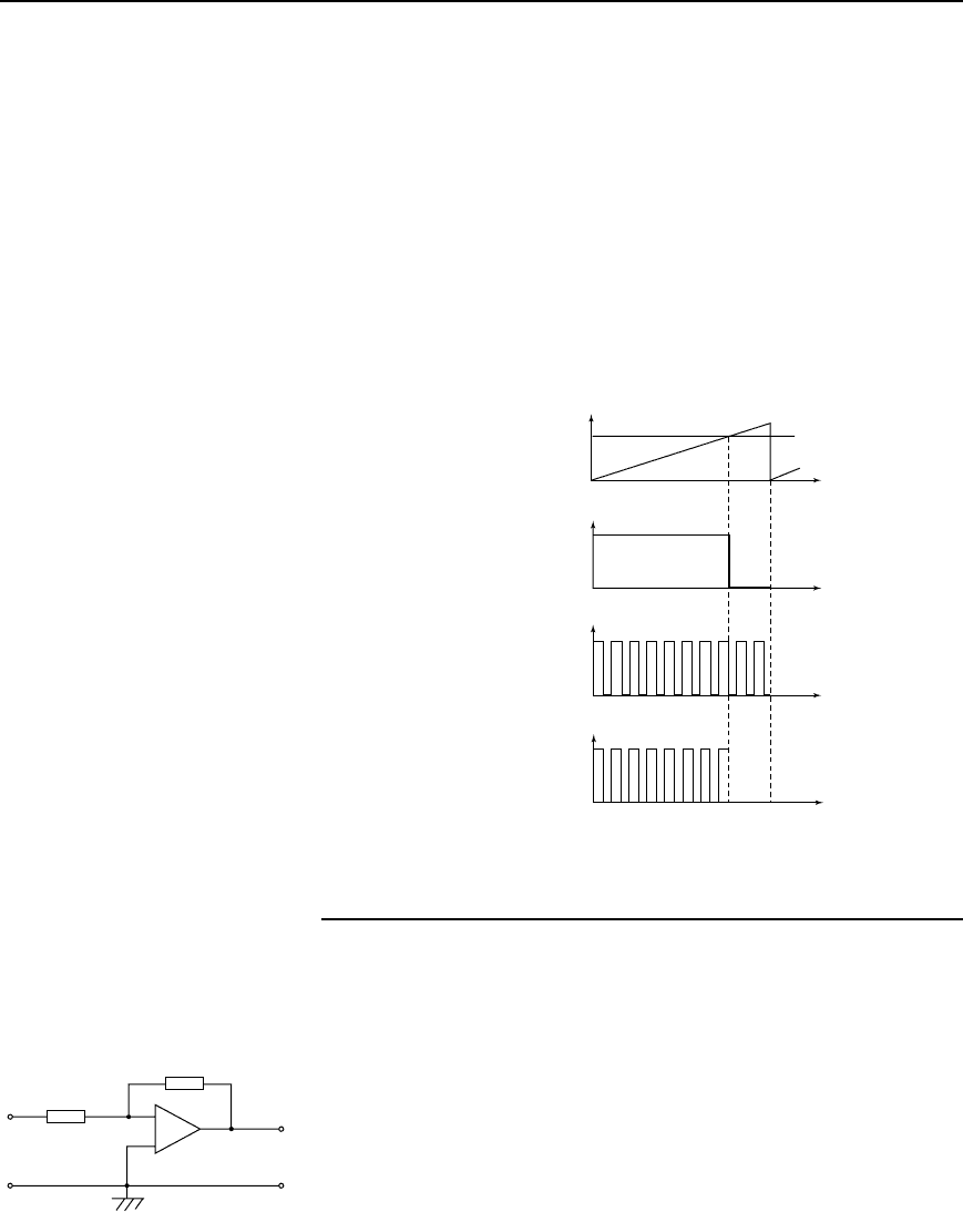
294 Electrical Circuit Theory and Technology
goes to 0 (i.e. ‘low’) as shown in Figure 18.20(b). The other input of the
AND gate is fed by a steady train of pulses from a pulse generator, as
shown in Figure 18.20(c). When both inputs to the AND gate are ‘high’,
the gate ‘opens’ and gives a ‘high’ output, i.e. a pulse, as shown in
Figure 18.20(d). The time taken by V
1
to reach V
2
is proportional to the
analogue voltage if the ramp is linear. The output pulses from the AND
gate are recorded by a binary counter and, as shown in Figure 18.20(e),
are the digital equivalent of the analogue input voltage V
2
. In practise, the
ramp generator is a D/A converter which takes its digital input from the
binary counter, shown by the broken lines in Figure 18.19. As the counter
advances through its normal binary sequence, a staircase waveform with
equal steps (i.e. a ramp) is built up at the output of the D/A converter (as
shown by the first few steps in Figure 18.18.
(a)
(b) Comparator
output
(c) Pulse
generator
(d) AND
gate
output
(e) Binary
output
0001
0010
0011
0100
0101
0110
0111
1000
t
t
t
t
1
0
V
2
V
1
Figure 18.20
18.12 Further problems
on operational amplifiers
Introduction to operational amplifiers
1. A differential amplifier has an open-loop voltage gain of 150 when
the input signals are 3.55V and 3.40V. Determine the output voltage
of the amplifier. [ 22.5 V ]
2. Calculate the differential voltage gain of an op amp that has a com-
mon-mode gain of 6.0 and a CMRR of 80 dB. [6 ð 10
4
]
R
1
= 15 kΩ
R
2
= 1.2 MΩ
V
i
V
o
+
−
Figure 18.21
3. A differential amplifier has an open-loop voltage gain of 150 and a
common input signal of 4.0 V to both terminals. An output signal of
15mV results. Determine the common-mode gain and the CMRR.
[3.75 ð 10
3
, 92.04 dB]
Operational amplifiers 295
4. In the inverting amplifier of Figure 18.5 (on page 282), R
i
D 1.5k
and R
f
D 2.5k. Determine the output voltage when the input voltage
is: (a) C0.6V(b) 0.9 V [(a) 1.0V (b)C1.5V]
5. The op amp shown in Figure 18.21 has an input bias current of
90nA at 20
°
C. Calculate (a) the voltage gain, and (b) the output offset
voltage due to the input bias current. [ (a) 80 (b) 1.33 mV ]
Input voltage
Output
voltage
0V
15 kΩ
6.8 kΩ
−
+
Figure 18.22
6. Determine (a) the value of the feedback resistor, and (b) the freque-
ncy for an inverting amplifier to have a voltage gain of 45dB, a
closed-loop bandwidth of 10kHz and an input resistance of 20k.
[(a) 3.56M (b) 1.78MHz]
Further operational amplifier calculations
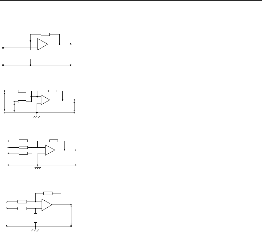
7. If the input voltage for the op amp shown in Figure 18.22, is 0.5V,
determine (a) the voltage gain (b) the output voltage
[(a) 3.21 (b) 1.60V ]
V
1
V
2
V
o
−
+
10 kΩ
10 kΩ
25 kΩ
Figure 18.23
8. In the circuit of Figure 18.23, determine the value of the output
voltage, V
o
,when(a)V
1
DC1VandV
2
DC3V(b)V
1
DC1Vand
V
2
D3V [(a) 10V (b) C5V]
0.3V
0.5V
0.8V
15 kΩ 60 kΩ
25 kΩ
32 kΩ
V
o
−
+
Figure 18.24
9. For the summing op amp shown in Figure 18.24, determine the output
voltage, V
o
.[3.9V]
10. A steady voltage of 1.25V is applied to an op amp integrator having
component values of R D 125k and C D 4.0
µF. Calculate the value
of the output voltage 120ms after applying the input, assuming that
the initial capacitor charge is zero. [ 0.3 V ]
11. In the differential amplifier shown in Figure 18.25, determine the
output voltage, V
o
, if: (a) V
1
D 4mV and V
2
D 0(b)V
1
D 0and
V
2
D 6mV (c) V
1
D 40mV and V
2
D 30mV (d) V
1
D 25mV and
V
2
D 40mV
[(a) 60mV (b) C90mV (c) 150mV (d) C225 mV]
120 kΩ
120 kΩ
8 kΩ
8 kΩ
V
1
V
o
V
2
1
2
0V
−
+
Figure 18.25
