Bird J. Electrical Circuit Theory and Technology
Подождите немного. Документ загружается.

Assignment 5
This assignment covers the material contained in chapters 15
to 18.
The marks for each question are shown in brackets at the end of
each question.
1 The power taken by a series inductive circuit when connected to a
100V, 100Hz supply is 250W and the current is 5A. Calculate (a) the
resistance, (b) the impedance, (c) the reactance, (d) the power factor,
and (e) the phase angle between voltage and current. (9)
2 A coil of resistance 20 and inductance 200mH is connected in
parallel with a 4
µF capacitor across a 50V, variable frequency supply.
Calculate (a) the resonant frequency, (b) the dynamic resistance,
(c) the current at resonance, and (d) the Q-factor at resonance. (10)
3 A series circuit comprises a coil of resistance 30 and inductance
50mH, and a 2500 pF capacitor. Determine the Q-factor of the circuit
at resonance. (4)
4 The winding of an electromagnet has an inductance of 110mH and
a resistance of 5.5 . When it is connected to a 110V, d.c. supply,
calculate (a) the steady state value of current flowing in the winding,
(b) the time constant of the circuit, (c) the value of the induced e.m.f.
after 0.1s, (d) the time for the current to rise to 75% of it’s final value,
and (e) the value of the current after 0.02s. (11)
1.5 V
1.0 V
15 kΩ
10 kΩ
30 kΩ
V
o
−
+
Figure A5.1
5 A single-phase motor takes 30A at a power factor of 0.65 lagging
from a 300V, 50Hz supply. Calculate (a) the current taken by a capac-
itor connected in parallel with the motor to correct the power factor
to unity, and (b) the value of the supply current after power factor
correction. (7)
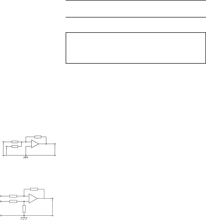
6 For the summing operational amplifier shown in Figure A5.1, deter-
mine the value of the output voltage, V
o
.(3)
7 In the differential amplifier shown in Figure A5.2, determine the
output voltage, V
o
when: (a) V
1
D 4mVandV
2
D 0(b)V
1
D 0and
V
2
D 5mV (c) V
1
D 20mV and V
2
D 10mV. (6)
V
1
V
2
V
o
120 kΩ
20 kΩ
120 kΩ
20 kΩ
OV
−
+
1
2
Figure A5.2
19 Three phase systems
At the end of this chapter you should be able to:
ž describe a single-phase supply
ž describe a three-phase supply
ž understand a star connection, and recognize that I
L
D I
p
and
V
L
D
p
3V
p
ž draw a complete phasor diagram for a balanced, star
connected load
ž understand a delta connection, and recognize that V
L
D V
p
and I
L
D
p
3I
p
ž draw a phasor diagram for a balanced, delta connected load
ž calculate power in three-phase systems using
P D
p
3V
L
I
L
cos
ž appreciate how power is measured in a three-phase system, by
the one, two and three-wattmeter methods
ž compare star and delta connections
ž appreciate the advantages of three-phase systems
19.1 Introduction
Generation, transmission and distribution of electricity via the National
Grid system is accomplished by three-phase alternating currents.
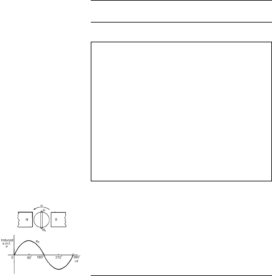
The voltage induced by a single coil when rotated in a uniform magnetic
field is shown in Figure 19.1 and is known as a single-phase voltage.
Most consumers are fed by means of a single-phase a.c. supply. Two
wires are used, one called the live conductor (usually coloured red) and
the other is called the neutral conductor (usually coloured black). The
neutral is usually connected via protective gear to earth, the earth wire
being coloured green. The standard voltage for a single-phase a.c. supply
is 240 V. The majority of single-phase supplies are obtained by connec-
tion to a three-phase supply (see Figure 19.5, page 299).
Figure 19.1
19.2 Three-phase supply
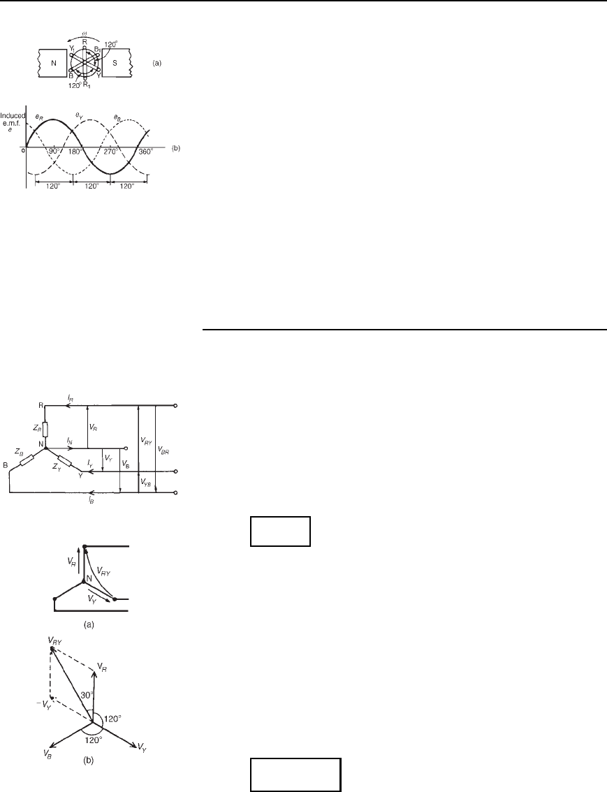
A three-phase supply is generated when three coils are placed 120
°
apart and the whole rotated in a uniform magnetic field as shown in
Figure 19.2(a). The result is three independent supplies of equal volt-
ages which are each displaced by 120
°
from each other as shown in
Figure 19.2(b).
(i) The convention adopted to identify each of the phase voltages is:
R-red, Y-yellow, and B-blue, as shown in Figure 19.2.
298 Electrical Circuit Theory and Technology
Figure 19.2
(ii) The phase-sequence is given by the sequence in which the conduc-
tors pass the point initially taken by the red conductor. The national
standard phase sequence is R, Y, B.
A three-phase a.c. supply is carried by three conductors, called ‘lines’
which are coloured red, yellow and blue. The currents in these conductors
are known as line currents (I
L
) and the p.d.’s between them are known
as line voltages (V
L
). A fourth conductor, called the neutral (coloured
black, and connected through protective devices to earth) is often used
with a three-phase supply.
If the three-phase windings shown in Figure 19.2 are kept independent
then six wires are needed to connect a supply source (such as a generator)
to a load (such as motor). To reduce the number of wires it is usual to
interconnect the three phases. There are two ways in which this can be
done, these being:
(a) a star connection,and(b)adelta,ormesh, connection. Sources
of three-phase supplies, i.e. alternators, are usually connected in star,
whereas three-phase transformer windings, motors and other loads may
be connected either in star or delta.
19.3 Star connection
(i) A star-connected load is shown in Figure 19.3 where the three line
conductors are each connected to a load and the outlets from the
loads are joined together at N to form what is termed the neutral
point or the star point.
(ii) The voltages, V
R
, V
Y
and V
B
are called phase voltages or line to
neutral voltages. Phase voltages are generally denoted by V
p
(iii) The voltages, V
RY
, V
YB
and V
BR
are called line voltages
Figure 19.3
(iv) From Figure 19.3 it can be seen that the phase currents (generally
denoted by I
p
) are equal to their respective line currents I
R
, I
Y
and
I
B
, i.e. for a star connection:
I
L
= I
p
(v) For a balanced system: I
R
D I
Y
D I
B
,V
R
D V
Y
D V
B
V
RY
D V
YB
D V
BR
,Z
R
D Z
Y
D Z
B
and the current in the neutral conductor, I
N
D 0
When a star connected system is balanced, then the neutral
conductor is unnecessary and is often omitted.
(vi) The line voltage, V
RY
, shown in Figure 19.4(a) is given by
V
RY
= V
R
− V
Y
(V
Y
is negative since it is in the opposite
direction to V
RY
). In the phasor diagram of Figure 19.4(b), phasor
V
Y
is reversed (shown by the broken line) and then added
phasorially to V
R
(i.e. V
RY
= V
R
Y .−V
Y
/). By trigonometry, or
by measurement, V
RY
D
p
3V
R
, i.e. for a balanced star connection:
V
L
=
p
3 V
p
Figure 19.4
Three phase systems 299
(See problem 3 following for a complete phasor diagram of a star-
connected system.)
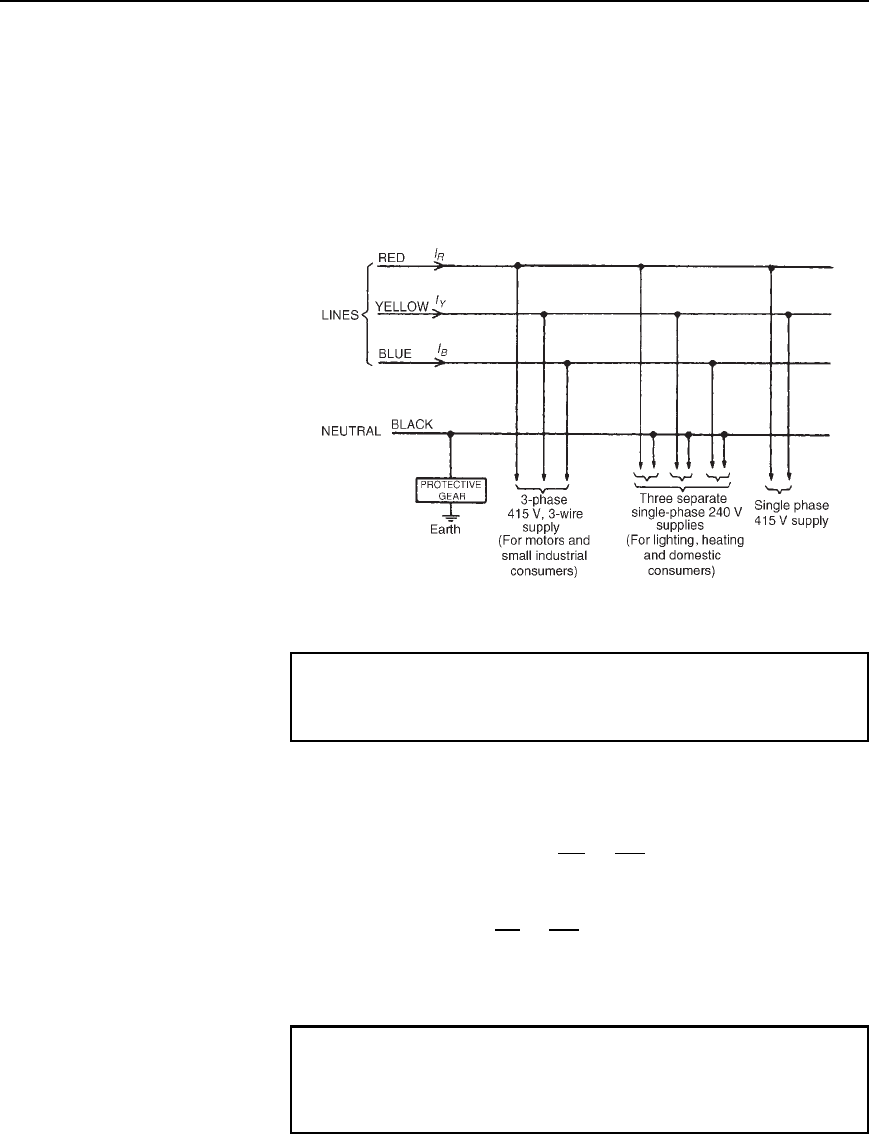
(vii) The star connection of the three phases of a supply, together with
a neutral conductor, allows the use of two voltages— the phase
voltage and the line voltage. A 4-wire system is also used when the
load is not balanced. The standard electricity supply to consumers
in Great Britain is 415/240 V, 50 Hz, 3-phase, 4-wire alternating
current, and a diagram of connections is shown in Figure 19.5.
Figure 19.5
Problem 1. Three loads, each of resistance 30 , are connected
in star to a 415 V, 3-phase supply. Determine (a) the system phase
voltage, (b) the phase current and (c) the line current.
A ‘415 V, 3-phase supply’ means that 415 V is the line voltage, V
L
(a) For a star connection, V
L
D
p
3V
p
Hence phase voltage, V
p
D
V
L
p
3
D
415
p
3
D 239.6 V or 240 V
correct to 3 significant figures
(b) Phase current, I
p
D
V
p
R
p
D
240
30
D 8A
(c) For a star connection, I
p
D I
L
Hence the line current, I
L
D 8A
Problem 2. A star-connected load consists of three identical coils
each of resistance 30 and inductance 127.3 mH. If the line
current is 5.08 A, calculate the line voltage if the supply frequency
is 50 Hz
300 Electrical Circuit Theory and Technology
Inductive reactance X
L
D 2fL D 250127.3 ð10
3
D 40
Impedance of each phase Z
p
D
R
2
C X
L
2
D
30
2
C 40
2
D 50
For a star connection I
L
D I
p
D
V
p
Z
p
Hence phase voltage V
p
D I
p
Z
p
D 5.0850 D 254 V
Line voltage V
L
D
p
3V
p
D
p
3254 D 440 V
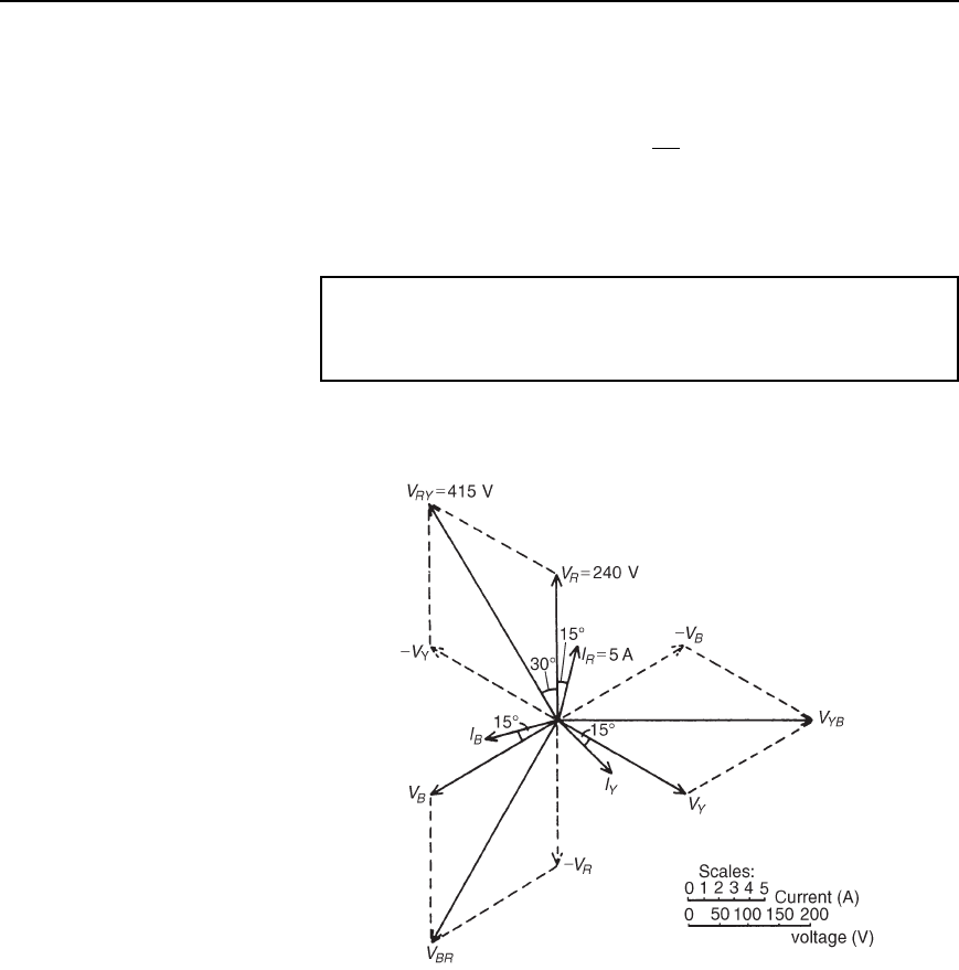
Problem 3. A balanced, three-wire, star-connected, 3-phase load
has a phase voltage of 240 V, a line current of 5 A and a lagging
power factor of 0.966. Draw the complete phasor diagram.
The phasor diagram is shown in Figure 19.6.
Figure 19.6
Procedure to construct the phasor diagram:
(i) Draw V
R
D V
Y
D V
B
D 240 V and spaced 120
°
apart. (Note that
V
R
is shown vertically upwards—this however is immaterial for it
may be drawn in any direction.)
(ii) Power factor D cos D 0.966 lagging. Hence the load phase angle
is given by arccos 0.966, i.e. 15
°
lagging. Hence I
R
D I
Y
D I
B
D
5 A, lagging V
R
, V
Y
and V
B
respectively by 15
°
Three phase systems 301
Figure 19.7
(iii) V
RY
D V
R
V
Y
(phasorially). Hence V
Y
is reversed and added
phasorially to V
R
. By measurement, V
RY
D 415 V (i.e.
p
3240)
and leads V
R
by 30
°
. Similarly, V
YB
D V
Y
V
B
and
V
BR
D V
B
V
R
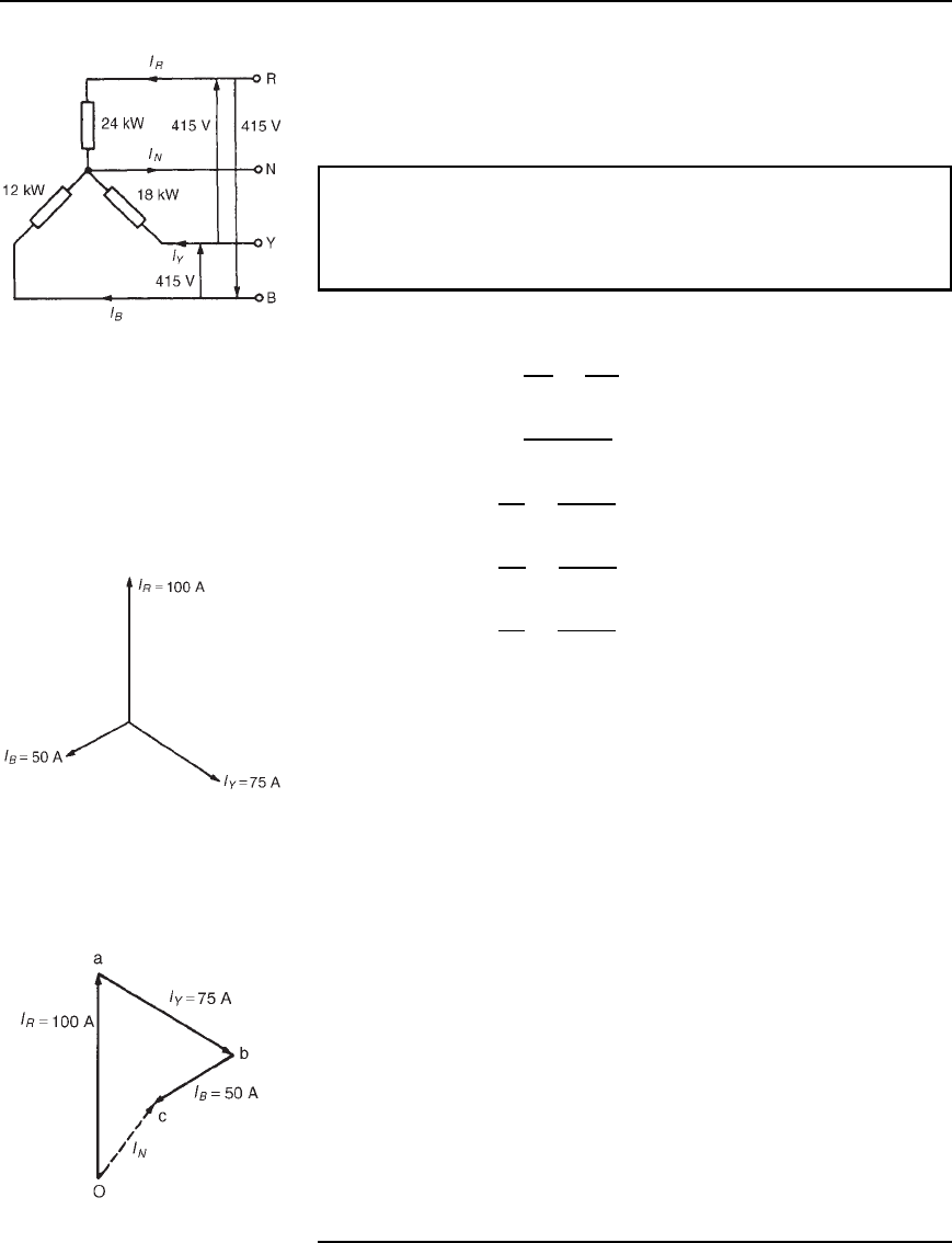
Problem 4. A 415 V, 3-phase, 4 wire, star-connected system
supplies three resistive loads as shown in Figure 19.7. Determine
(a) the current in each line and (b) the current in the neutral
conductor.
(a) For a star-connected system V
L
D
p
3V
p
Hence V
p
D
V
L
p
3
D
415
p
3
D 240 V
Since current I D
Power P
Voltage V
for a resistive load
then I
R
D
P
R
V
R
D
24000
240
D 100 A
I
Y
D
P
Y
V
Y
D
18000
240
D 75 A
and I
B
D
P
B
V
B
D
12000
240
D 50 A
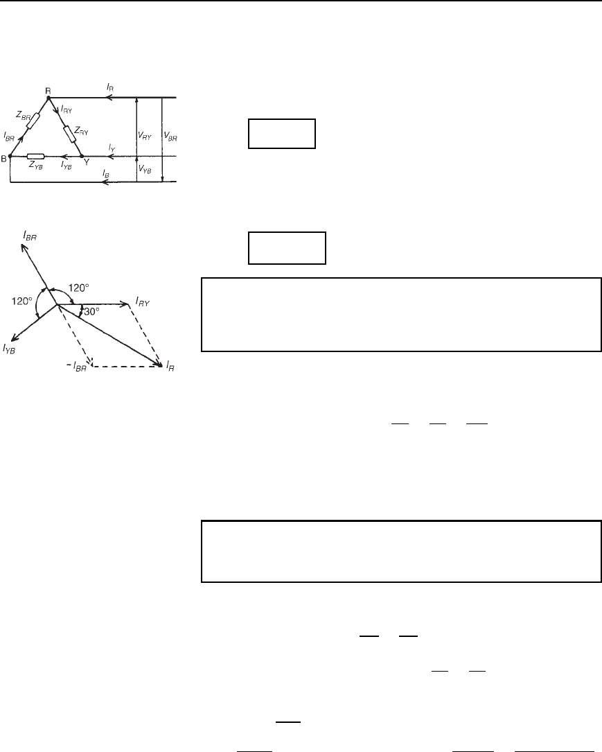
(b) The three line currents are shown in the phasor diagram of
Figure 19.8. Since each load is resistive the currents are in phase
with the phase voltages and are hence mutually displaced by 120
°
.
The current in the neutral conductor is given by:
I
N
D I
R
C I
Y
C I
B
phasorially.
Figure 19.8
Figure 19.9 shows the three line currents added phasorially. oa represents
I
R
in magnitude and direction. From the nose of oa, ab is drawn
representing I
Y
in magnitude and direction. From the nose of ab, bc
is drawn representing I
B
in magnitude and direction. oc represents the
resultant, I
N
.
By measurement, I
N
= 43 A
Alternatively, by calculation, considering I
R
at 90
°
,I
B
at 210
°
and I
Y
at
330
°
:
Total horizontal component D 100cos90
°
C 75cos330
°
C 50cos210
°
D 21.65
Total vertical component D 100 sin 90
°
C 75sin330
°
C 50sin210
°
D 37.50
Hence magnitude of I
N
D
21.65
2
C 37.50
2
D 43.3A
Figure 19.9
302 Electrical Circuit Theory and Technology
19.4 Delta connection
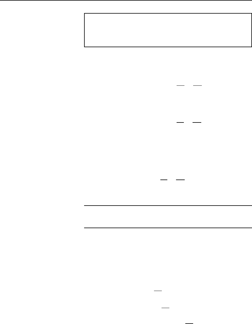
(i) A delta (or mesh) connected load is shown in Figure 19.10 where
the end of one load is connected to the start of the next load.
(ii) From Figure 19.10, it can be seen that the line voltages V
RY
,V
YB
and V
BR
are the respective phase voltages, i.e. for a delta
connection:
V
L
= V
p
Figure 19.10
(iii) Using Kirchhoff’s current law in Figure 19.10, I
R
D I
RY
I
BR
D
I
RY
C I
BR
. From the phasor diagram shown in Figure 19.11,
by trigonometry or by measurement, I
R
D
p
3I
RY
, i.e. for a delta
connection:
I
L
=
p
3I
p
Problem 5. Three identical coils each of resistance 30 and
inductance 127.3 mH are connected in delta to a 440 V, 50 Hz,
3-phase supply. Determine (a) the phase current, and (b) the line
current.
Figure 19.11
Phase impedance, Z
p
D 50 (from problem 2) and for a delta
connection, V
p
D V
L
(a) Phase current, I
p
D
V
p
Z
p
D
V
L
Z
p
D
440
50
D 8.8A
(b) For a delta connection, I
L
D
p
3I
p
D
p
38.8 D 15.24 A
Thus when the load is connected in delta, three times the line current is
taken from the supply than is taken if connected in star.
Problem 6. Three identical capacitors are connected in delta to a
415 V, 50 Hz, 3-phase supply. If the line current is 15 A, determine
the capacitance of each of the capacitors.
For a delta connection I
L
D
p
3I
p
Hence phase current I
p
D
I
L
p
3
D
15
p
3
D 8.66 A
Capacitive reactance per phase, X
C
D
V
p
I
p
D
V
L
I
p
(since for a delta
connection V
L
D V
p
)
Hence X
C
D
415
8.66
D 47.92
X
C
D
1
2fC
, from which capacitance, C D
1
2fX
C
D
1
25047.92
F
D 66.43 mF
Three phase systems 303
Problem 7. Three coils each having resistance 3 and inductive
reactance 4 are connected (i) in star and (ii) in delta to a 415 V,
3-phase supply. Calculate for each connection (a) the line and phase
voltages and (b) the phase and line currents.
(i) For a star connection: I
L
D I
p
and V
L
D
p
3V
p
(a) A 415 V, 3-phase supply means that the
line voltage, V
L
D 415 V
Phase voltage, V
p
D
V
L
p
3
D
415
p
3
D 240 V
(b) Impedance per phase, Z
p
D
R
2
C X
L
2
D
3
2
C 4
2
D 5
Phase current, I
p
D
V
p
Z
p
D
240
5
D 48 A
Line current, I
L
D I
p
D 48 A
(ii) For a delta connection: V
L
D V
p
and I
L
D
p
3I
p
(a) Line voltage, V
L
D 415 V
Phase voltage, V
p
D V
L
D 415 V
(b) Phase current, I
p
D
V
p
Z
p
D
415
5
D 83 A
Line current, I
L
D
p
3I
p
D
p
383 D 144 A
Further problems on star and delta connections may be found in
Section 19.9, problems 1 to 7, page 312.
19.5 Power in
three-phase systems
The power dissipated in a three-phase load is given by the sum of the
power dissipated in each phase. If a load is balanced then the total power
P is given by: P D 3 ðpower consumed by one phase.
The power consumed in one phase D I
p
2
R
p
or V
p
I
p
cos (where is
the phase angle between V
p
and I
p
)
For a star connection, V
p
D
V
L
p
3
and I
p
D I
L
hence
P D 3
V
L
p
3
I
L
cos D
p
3V
L
I
L
cos
For a delta connection, V
p
D V
L
and I
p
D
I
L
p
3
hence
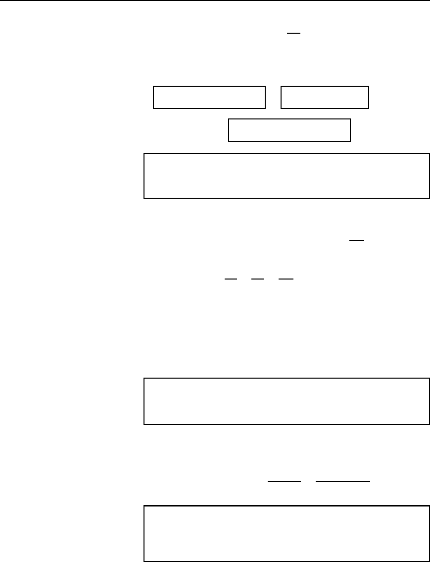
304 Electrical Circuit Theory and Technology
P D 3V
L
I
L
p
3
cos D
p
3V
L
I
L
cos
Hence for either a star or a delta balanced connection the total power P
is given by:
P =
p
3V
L
I
L
cosf watts
or
P = 3I
p
2
R
p
watts.
Total volt-amperes,
S =
p
3V
L
I
L
volt-amperes
Problem 8. Three 12 resistors are connected in star to a
415 V, 3-phase supply. Determine the total power dissipated by
the resistors.
Power dissipated, P D
p
3V
L
I
L
cos or P D 3I
p
2
R
p
Line voltage, V
L
D 415 V and phase voltage V
p
D
415
p
3
D 240 V
(since the resistors are star-connected)
Phase current, I
p
D
V
p
Z
p
D
V
p
R
p
D
240
12
D 20 A
For a star connection I
L
D I
p
D 20 A
For a purely resistive load, the power factor D cos D 1
Hence power P D
p
3V
L
I
L
cos D
p
3415201 D 14.4kW
or power P D 3I
p
2
R
p
D 320
2
12 D 14.4kW
Problem 9. The input power to a 3-phase a.c. motor is measured
as 5 kW. If the voltage and current to the motor are 400 V and
8.6 A respectively, determine the power factor of the system.
Power, P D 5000 W; Line voltage V
L
D 400 V; Line current, I
L
D 8.6A
Power, P D
p
3V
L
I
L
cos
Hence power factor D cos D
P
p
3V
L
I
L
D
5000
p
34008.6
D 0.839
Problem 10. Three identical coils, each of resistance 10 and
inductance 42 mH are connected (a) in star and (b) in delta to a
415 V, 50 Hz, 3-phase supply. Determine the total power dissipated
in each case.
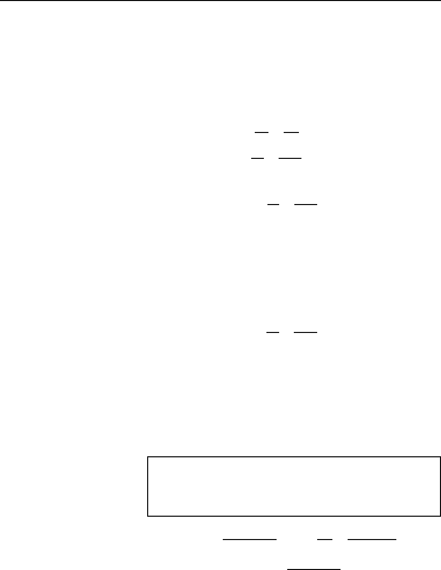
Three phase systems 305
(a) Star connection
Inductive reactance X
L
D 2fL D 25042 ð 10
3
D 13.19
Phase impedance Z
p
D
R
2
C X
2
L
D
10
2
C 13.19
2
D 16.55
Line voltage V
L
D 415 V and
phase voltage, V
p
D
V
L
p
3
D
415
p
3
D 240 V
Phase current, I
p
D
V
p
Z
p
D
240
16.55
D 14.50 A
Line current, I
L
D I
p
D 14.50 A
Power factor D cos D
R
p
Z
p
D
10
16.55
D 0.6042 lagging
Power dissipated, P D
p
3V
L
I
L
cos D
p
341514.500.6042
D 6.3kW
(Alternatively, P D 3I
p
2
R
p
D 314.50
2
10 D 6.3kW
(b) Delta connection
V
L
D V
p
D 415 V,Z
p
D 16.55 ,
cos D 0.6042 lagging (from above).
Phase current, I
p
D
V
p
Z
p
D
415
16.55
D 25.08 A
Line current, I
L
D
p
3I
p
D
p
325.08 D 43.44 A
Power dissipated, P D
p
3V
L
I
L
cos D
p
341543.440.6042
D 18.87 kW
(Alternatively, P D 3I
p
2
R
p
D 325.08
2
10 D 18.87 kW
Hence loads connected in delta dissipate three times the power than when
connected in star, and also take a line current three times greater.
Problem 11. A 415 V, 3-phase a.c. motor has a power output of
12.75 kW and operates at a power factor of 0.77 lagging and with
an efficiency of 85%. If the motor is delta-connected, determine
(a) the power input, (b) the line current and (c) the phase current.
(a) Efficiency D
power output
power input
, hence
85
100
D
12750
power input
from which, power input D
12750 ð 100
85
D 15000Wor15kW
