Bird J. Electrical Circuit Theory and Technology
Подождите немного. Документ загружается.


346 Electrical Circuit Theory and Technology
Equivalent circuit of a transformer
18 A transformer has 1200 primary turns and 200 secondary turns. The
primary and secondary resistances are 0.2 and 0.02 respectively
and the corresponding leakage reactances are 1.2 and 0.05
respectively. Calculate (a) the equivalent resistance, reactance and
impedance referred to the primary winding, and (b) the phase angle
of the impedance. [(a) 0.92 ,3.0,3.14 (b) 72.95
°
]
Regulation
19 A 6 kVA, 100 V/500 V, single-phase transformer has a secondary
terminal voltage of 487.5 volts when loaded. Determine the regula-
tion of the transformer. [2.5%]
20 A transformer has an open circuit voltage of 110 volts. A tap-
changing device operates when the regulation falls below 3%.
Calculate the load voltage at which the tap-changer operates.
[106.7 volts]
Losses and efficiency
21 A single-phase transformer has a voltage ratio of 6:1 and the h.v.
winding is supplied at 540 V. The secondary winding provides a full
load current of 30 A at a power factor of 0.8 lagging. Neglecting
losses, find (a) the rating of the transformer, (b) the power supplied
to the load, (c) the primary current.
[(a) 2.7 kVA, (b) 2.16 kW, (c) 5 A]
22 A single-phase transformer is rated at 40 kVA. The transformer has
full-load copper losses of 800 W and iron losses of 500 W. Deter-
mine the transformer efficiency at full load and 0.8 power factor.
[96.10%]
23 Determine the efficiency of the transformer in problem 22 at half
full-load and 0.8 power factor. [95.81%]
24 A 100 kVA, 2000 V/400 V, 50 Hz, single-phase transformer has an
iron loss of 600 W and a full-load copper loss of 1600 W. Calculate
its efficiency for a load of 60 kW at 0.8 power factor. [97.56%]
25 (a) What are eddy currents? State how their effect is reduced in
transformers.
(b) Determine the efficiency of a 15 kVA transformer for the
following conditions:
(i) full-load, unity power factor
(ii) 0.8 full-load, unity power factor
(iii) half full-load, 0.8 power factor.

Transformers 347
Assume that iron losses are 200 W and the full-load copper loss is
300 W. [(a) 96.77% (ii) 96.84% (iii) 95.62%]
26 A 250 kVA transformer has a full load copper loss of 3 kW and
an iron loss of 2 kW. Calculate (a) the output kVA at which the
efficiency of the transformer is a maximum, and (b) the maximum
efficiency, assuming the power factor of the load is 0.80.
[(a) 204.1 kVA (b) 97.61%]
Resistance matching
27 A transformer having a turns ratio of 8:1 supplies a load of resistance
50 . Determine the equivalent input resistance of the transformer.
[3.2 k]
28 What ratio of transformer is required to make a load of resistance
30 appear to have a resistance of 270 ? [3:1]
29 A single-phase, 240 V/2880 V ideal transformer is supplied from a
240 V source through a cable of resistance 3 . If the load across
the secondary winding is 720 determine (a) the primary current
flowing and (b) the power dissipated in the load resistance.
[(a) 30 A (b) 4.5 kW]
30 A load of resistance 768 is to be matched to an amplifier which
has an effective output resistance of 12 . Determine the turns ratio
of the coupling transformer. [1:8]
31 An a.c. source of 20 V and internal resistance 20 k is matched to
a load by a 16:1 single-phase transformer. Determine (a) the value
of the load resistance and (b) the power dissipated in the load.
[(a) 78.13 (b) 5 mW]
Auto-transformer
32 A single-phase auto transformer has a voltage ratio of 480 V:300 V
and supplies a load of 30 kVA at 300 V. Assuming an ideal trans-
former, calculate the current in each section of the winding.
[I
1
D 62.5 A, I
2
D 100 A, I
2
I
1
D 37.5 A]
33 Calculate the saving in the volume of copper used in an auto
transformer compared with a double-wound transformer for (a) a
300 V:240 V transformer, and (b) a 400 V:100 V transformer.
[(a) 80% (b) 25%]
Three-phase transformer
34 A three-phase transformer has 600 primary turns and 150 secondary
turns. If the supply voltage is 1.5 kV determine the secondary line
voltage on no-load when the windings are connected (a) delta-star,
(b) star-delta. [(a) 649.5 V (b) 216.5 V]

348 Electrical Circuit Theory and Technology
Current transformer
35 A current transformer has two turns on the primary winding and a
secondary winding of 260 turns. The secondary winding is connected
to an ammeter with a resistance of 0.2 . The resistance of the
secondary winding is 0.3 . If the current in the primary winding is
650 A, determine (a) the reading on the ammeter, (b) the potential
difference across the ammeter, and (c) the total load in VA on the
secondary. [(a
)5A(b)1V(c)7.5VA]
Assignment 6
This assignment covers the material contained in chapters 19
and 20.
The marks for each question are shown in brackets at the end of
each question.
1 Three identical coils each of resistance 40 and inductive reactance
30 are connected (i) in star, and (ii) in delta to a 400 V, three-phase
supply. Calculate for each connection (a) the line and phase voltages,
(b) the phase and line currents, and (c) the total power dissipated.
(12)
2 Two wattmeters are connected to measure the input power to a
balanced three-phase load by the two-wattmeter method. If the
instrument readings are 10 kW and 6 kW, determine (a) the total
power input, and (b) the load power factor. (5)
3 An ideal transformer connected to a 250 V mains, supplies a 25 V,
200 W lamp. Calculate the transformer turns ratio and the current
taken from the supply. (5)
4 A 200 kVA, 8000 V/320 V, 50 Hz single phase transformer has 120
secondary turns. Determine (a) the primary and secondary currents,
(b) the number of primary turns, and (c) the maximum value of flux.
(9)
5 Determine the percentage regulation of an 8 kVA, 100 V/200 V,
single phase transformer when it’s secondary terminal voltage is
194 V when loaded. (3)
6 A 500 kVA rated transformer has a full-load copper loss of 4 kW and
an iron loss of 3 kW. Determine the transformer efficiency (a) at full
load and 0.80 power factor, and (b) at half full load and 0.80 power
factor. (10)
7 Determine the optimum value of load resistance for maximum power
transfer if the load is connected to an amplifier of output resistance
288 through a transformer with a turns ratio 6:1. (3)
8 A single-phase auto transformer has a voltage ratio of 250 V:200 V
and supplies a load of 15 kVA at 200 V. Assuming an ideal trans-
former, determine the current in each section of the winding. (3)
21 D.c. machines
At the end of this chapter you should be able to:
ž distinguish between the function of a motor and a generator
ž describe the action of a commutator
ž describe the construction of a d.c. machine
ž distinguish between wave and lap windings
ž understand shunt, series and compound windings of d.c.
machines
ž understand armature reaction
ž calculate generated e.m.f. in an armature winding using
E D
2pnZ
c
ž describe types of d.c. generator and their characteristics
ž calculate generated e.m.f. for a generator using E D V C I
a
R
a
ž state typical applications of d.c. generators
ž list d.c. machine losses and calculate efficiency
ž calculate back e.m.f. for a d.c. motor using E D V I
a
R
a
ž calculate the torque of a d.c. motor using T D
EI
a
2n
and
T D
pZI
a
c
ž describe types of d.c. motor and their characteristics
ž state typical applications of d.c. motors
ž describe a d.c. motor starter
ž describe methods of speed control of d.c. motors
ž list types of enclosure for d.c. motors
21.1 Introduction
When the input to an electrical machine is electrical energy, (seen as
applying a voltage to the electrical terminals of the machine), and the
output is mechanical energy, (seen as a rotating shaft), the machine is
called an electric motor. Thus an electric motor converts electrical energy
into mechanical energy.
The principle of operation of a motor is explained in Section 8.4,
page 96.
When the input to an electrical machine is mechanical energy, (seen as,
say, a diesel motor, coupled to the machine by a shaft), and the output is
D.c. machines 351
electrical energy, (seen as a voltage appearing at the electrical terminals
of the machine), the machine is called a generator. Thus, a generator
converts mechanical energy to electrical energy.
The principle of operation of a generator is explained in
Section 9.2, page 101.
21.2 The action of a
commutator
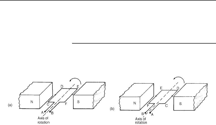
In an electric motor, conductors rotate in a uniform magnetic field. A
single-loop conductor mounted between permanent magnets is shown in
Figure 21.1. A voltage is applied at points A and B in Figure 21.1(a).
Figure 21.1
A force, F, acts on the loop due to the interaction of the magnetic
field of the permanent magnets and the magnetic field created by the
current flowing in the loop. This force is proportional to the flux density,
B, the current flowing, I, and the effective length of the conductor, l,
i.e. F D BIl. The force is made up of two parts, one acting vertically
downwards due to the current flowing from C to D and the other acting
vertically upwards due to the current flowing from E to F (from Fleming’s
left hand rule). If the loop is free to rotate, then when it has rotated
through 180
°
, the conductors are as shown in Figure 21.1(b). For rotation
to continue in the same direction, it is necessary for the current flow
to be as shown in Figure 21.1(b), i.e. from D to C and from F to E.
This apparent reversal in the direction of current flow is achieved by a
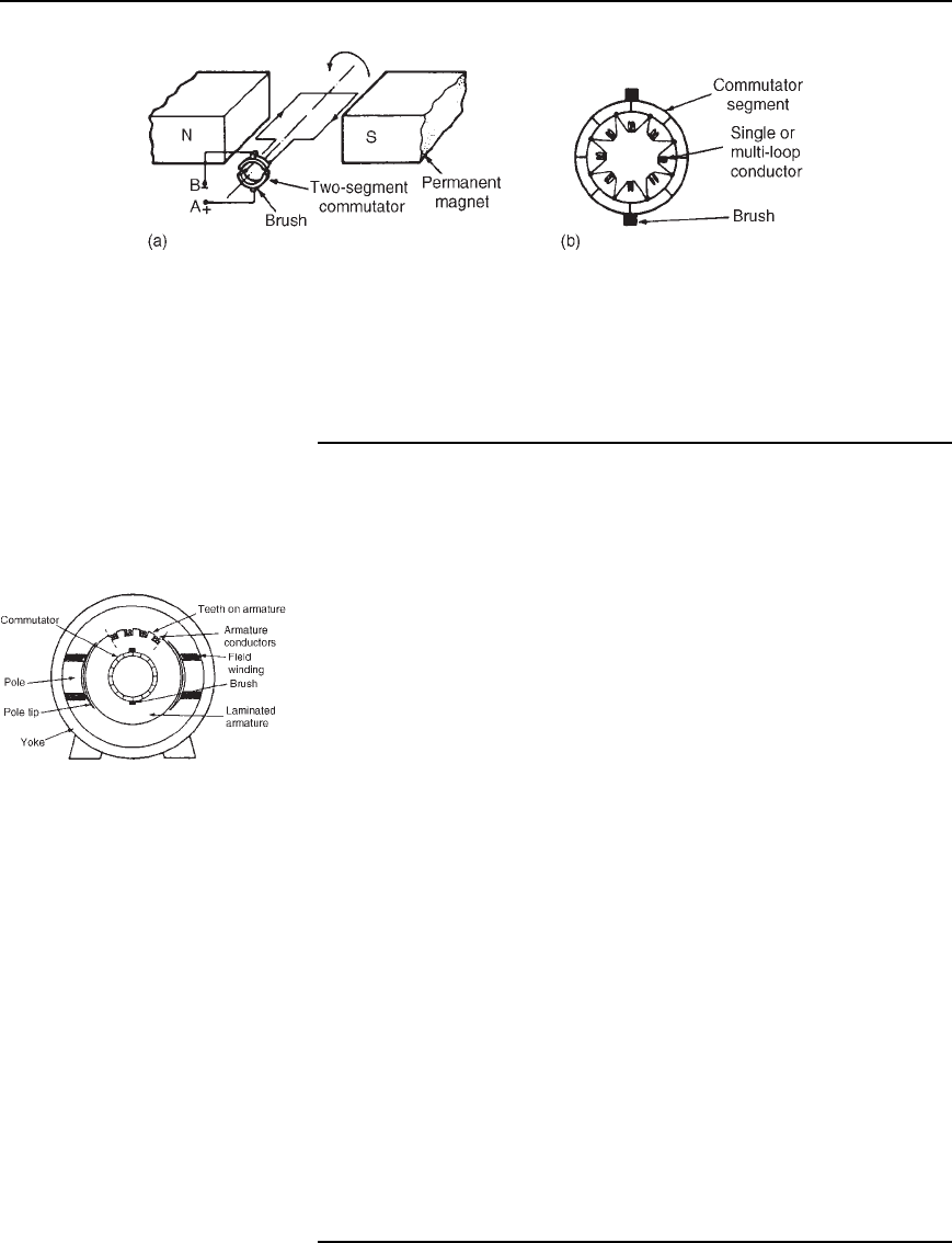
process called commutation. With reference to Figure 21.2(a), when a
direct voltage is applied at A and B, then as the single-loop conductor
rotates, current flow will always be away from the commutator for the
part of the conductor adjacent to the N-pole and towards the commutator
for the part of the conductor adjacent to the S-pole. Thus the forces act to
give continuous rotation in an anti-clockwise direction. The arrangement
shown in Figure 21.2(a) is called a ‘two-segment’ commutator and the
voltage is applied to the rotating segments by stationary brushes, (usually
carbon blocks), which slide on the commutator material, (usually copper),
when rotation takes place.
In practice, there are many conductors on the rotating part of a
d.c. machine and these are attached to many commutator segments.
A schematic diagram of a multi-segment commutator is shown in
Figure 21.2(b).
352 Electrical Circuit Theory and Technology
Figure 21.2
Poor commutation results in sparking at the trailing edge of the brushes.
This can be improved by using interpoles (situated between each pair of
main poles), high resistance brushes, or using brushes spanning several
commutator segments.
21.3 D.c. machine
construction
The basic parts of any d.c. machine are shown in Figure 21.3, and
comprise:
(a) a stationary part called the stator having,
(i) a steel ring called the yoke, to which are attached
(ii) the magnetic poles, around which are the
(iii) field windings, i.e. many turns of a conductor wound round
the pole core; current passing through this conductor creates
an electromagnet, (rather than the permanent magnets shown
in Figures 21.1 and 21.2),
(b) a rotating part called the armature mounted in bearings housed in
the stator and having,
Figure 21.3
(iv) a laminated cylinder of iron or steel called the core,onwhich
teeth are cut to house the
(v) armature winding, i.e. a single or multi-loop conductor
system and
(vi) the commutator, (see Section 21.2).
Armature windings can be divided into two groups, depending on how
the wires are joined to the commutator. These are called wave windings
and lap windings.
(a) In wave windings there are two paths in parallel irrespective of the
number of poles, each path supplying half the total current output.
Wave wound generators produce high voltage, low current outputs.
(b) In lap windings there are as many paths in parallel as the machine
has poles. The total current output divides equally between them.
Lap wound generators produce high current, low voltage output.
D.c. machines 353
21.4 Shunt, series and
compound windings
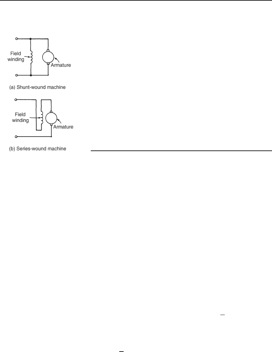
When the field winding of a d.c. machine is connected in parallel with
the armature, as shown in Figure 21.4(a), the machine is said to be shunt
wound. If the field winding is connected in series with the armature, as
shown in Figure 21.4(b), then the machine is said to be series wound.
A compound wound machine has a combination of series and shunt
windings.
Depending on whether the electrical machine is series wound, shunt
wound or compound wound, it behaves differently when a load is applied.
The behaviour of a d.c. machine under various conditions is shown by
means of graphs, called characteristic curves or just characteristics. The
characteristics shown in the following sections are theoretical, since they
neglect the effects of armature reaction.
Armature reaction is the effect that the magnetic field produced by the
armature current has on the magnetic field produced by the field system.
In a generator, armature reaction results in a reduced output voltage, and
in a motor, armature reaction results in increased speed.
A way of overcoming the effect of armature reaction is to fit compen-
sating windings, located in slots in the pole face.
Figure 21.4
21.5 E.m.f. generated in
an armature winding
Let Z D number of armature conductors,
D useful flux per pole, in webers
p D number of pairs of poles
and n D armature speed in rev/s
The e.m.f. generated by the armature is equal to the e.m.f. generated by
one of the parallel paths. Each conductor passes 2p poles per revolution
and thus cuts 2p webers of magnetic flux per revolution. Hence flux cut
by one conductor per second D 2pn Wb and so the average e.m.f. E
generated per conductor is given by:
E D 2pn volts since 1 volt D 1 Weber per second
Let c D number of parallel paths through the winding between positive
and negative brushes
c
= 2 for a wave winding
c
= 2p for a lap winding
The number of conductors in series in each path D
Z
c
The total e.m.f. between brushes
D (average e.m.f./conductor)(number of conductors in series per path)
D 2pn
Z
c
354 Electrical Circuit Theory and Technology
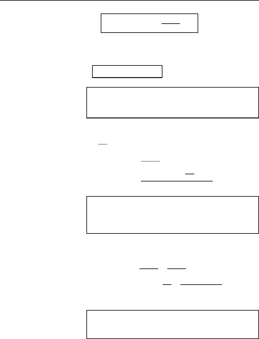
i.e.,
generated e.m.f., E =
2p8nZ
c
volts
21.1
Since Z, p and c are constant for a given machine, then E / n.
However 2n is the angular velocity ω in radians per second, hence the
generated e.m.f. is proportional to and ω, i.e.,
generated e.m.f., E ∝ 8!
21.2
Problem 1. An 8-pole, wave-connected armature has 600 conduc-
tors and is driven at 625 rev/min. If the flux per pole is 20 mWb,
determine the generated e.m.f.
Z D 600, c D 2 (for a wave winding), p D 4 pairs
n D
625
60
rev/s, D 20 ð 10
3
Wb
Generated e.m.f., E D
2pnZ
c
D
2420 ð 10
3
625
60
600
2
D 500 volts
Problem 2. A 4-pole generator has a lap-wound armature with
50 slots with 16 conductors per slot. The useful flux per pole is
30 mWb. Determine the speed at which the machine must be driven
to generate an e.m.f. of 240 V.
E D 240 V, c D 2p (for a lap winding), Z D 50 ð 16 D 800,
D 30 ð 10
3
Wb.
Generated e.m.f. E D
2pnZ
c
D
2pnZ
2p
D nZ
Rearranging gives, speed, n D
E
Z
D
240
30 ð 10
3
800
D 10 rev=s or 600 rev=min
Problem 3. An 8-pole, lap-wound armature has 1200 conductors
and a flux per pole of 0.03 Wb. Determine the e.m.f. generated
when running at 500 rev/min.
D.c. machines 355
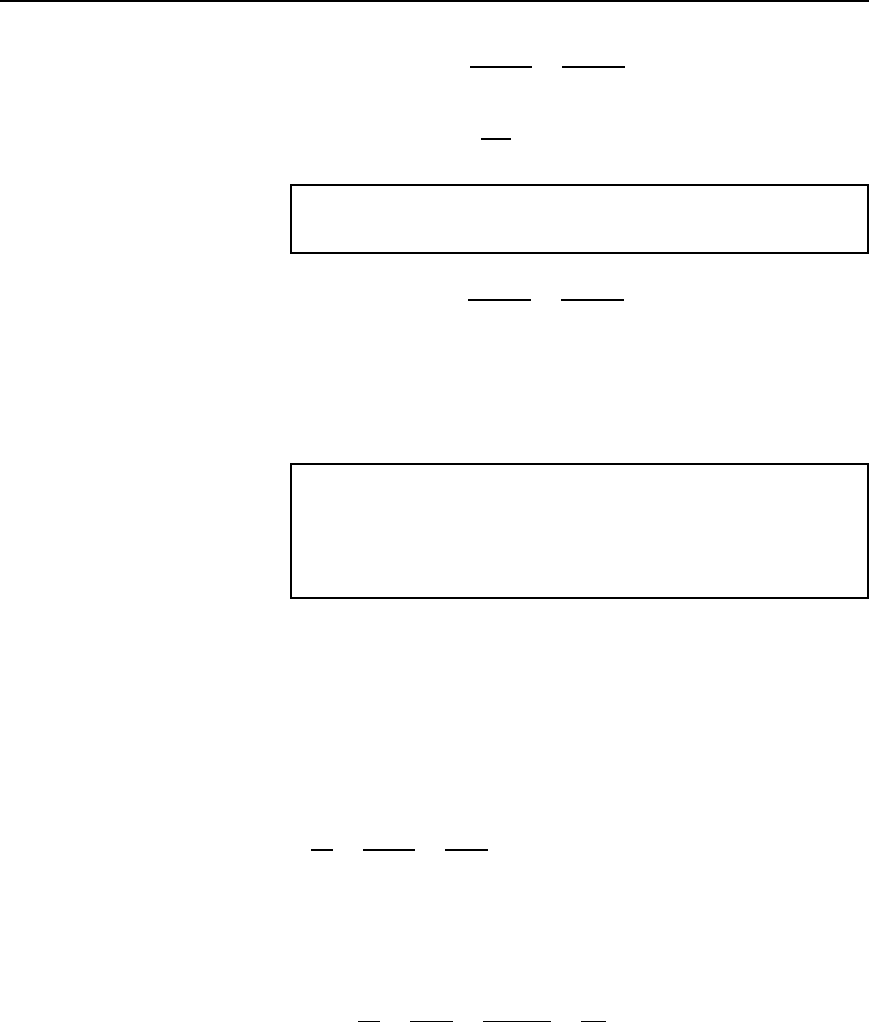
Generated e.m.f., E D
2pnZ
c
D
2pnZ
2p
, for a lap-wound machine, i.e.,
E D nZ D 0.03
500
60
1200 D 300 volts
Problem 4. Determine the generated e.m.f. in problem 3 if the
armature is wave-wound.
Generated e.m.f. E D
2pnZ
c
D
2pnZ
2
(since c D2 for wave-wound
D pnZ D 4nZ
D 4300 from problem 3,
D 1200 volts
Problem 5. A d.c. shunt-wound generator running at constant
speed generates a voltage of 150 V at a certain value of field
current. Determine the change in the generated voltage when the
field current is reduced by 20%, assuming the flux is proportional
to the field current.
The generated e.m.f. E of a generator is proportional to ω, i.e. is propor-
tional to n, where is the flux and n is the speed of rotation.
It follows that E D kn, where k is a constant.
At speed n
1
and flux
1
, E
1
D k
1
n
1
.
At speed n
2
and flux
2
, E
2
D k
2
n
2
.
Thus, by division:
E
1
E
2
D
k
1
n
1
k
2
n
2
D
1
n
1
2
n
2
The initial conditions are E
1
D 150 V, D
1
and n D n
1
. When the
flux is reduced by 20%, the new value of flux is 80/100 or 0.8 of the
initial value, i.e.
2
D 0.8
1
. Since the generator is running at constant
speed, n
2
D n
1
.
Thus
E
1
E
2
D
1
n
1
2
n
2
D
1
n
1
0.8
1
n
1
D
1
0.8
that is, E
2
D 150 ð 0.8 D 120 V
Thus, a reduction of 20% in the value of the flux reduces the generated
voltage to 120 V at constant speed.
