Bird J. Electrical Circuit Theory and Technology
Подождите немного. Документ загружается.

438 Electrical Circuit Theory and Technology
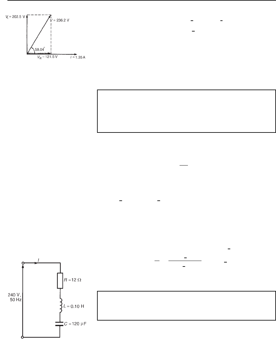
Figure 24.13
Supply voltage, V D IZ D 1.35
6
0
°
174.93
6
59.04
°
= 236.2
66
59.04
°
Vor.121.5 Y j202.5/V
(b) Voltage across 90 resistor, V
R
= 121.5V(since V D V
R
C jV
L
)
(c) Voltage across inductance, V
L
= 202.5Vleading V
R
by 90
°
.
(d) Circuit phase angle is the angle between the supply current and
voltage, i.e., 59.04
°
lagging(i.e., current lags voltage). The phasor
diagram is shown in Figure 24.13.
Problem 9. A coil of resistance 25 and inductance 20 mH has
an alternating voltage given by
v D 282.8sin628.4t C /3 volts
applied across it. Determine (a) the rms value of voltage (in polar
form), (b) the circuit impedance, (c) the rms current flowing, and
(d) the circuit phase angle.
(a) Voltage v D 282.8sin628.4t C/3 volts means V
m
D 282.8V,
hence rms voltage
V D 0.707 ð 282.8
or
1
p
2
ð 282.8
,
i.e., V D 200 V
In complex form the rms voltage may be expressed as
200
66
p=3Vor200
66
60
°
V
(b) ω D 2f D 628.4 rad/s, hence frequency
f D 628.4/2 D 100 Hz
Inductive reactance X
L
D 2fL D 210020 ð 10
3
D 12.57
Hence circuit impedance Z D R C jX
L
D .25 Y j12.57/Z or
27.98
66
26.69
°
Z
(c) Rms current, I D
V
Z
D
200
6
60
°
27.98
6
26.69
°
D 7.148
66
33.31
°
A
(d) Circuit phase angle is the angle between current I and voltage V,
i.e., 60
°
33.31
°
= 26.69
°
lagging.
Problem 10. A 240 V, 50 Hz voltage is applied across a series
circuit comprising a coil of resistance 12 and inductance 0.10 H,
and 120
µF capacitor. Determine the current flowing in the circuit.
The circuit diagram is shown in Figure 24.14.
Inductive reactance, X
L
D 2fL D 2500.10 D 31.4
Figure 24.14
Application of complex numbers to series a.c. circuits 439
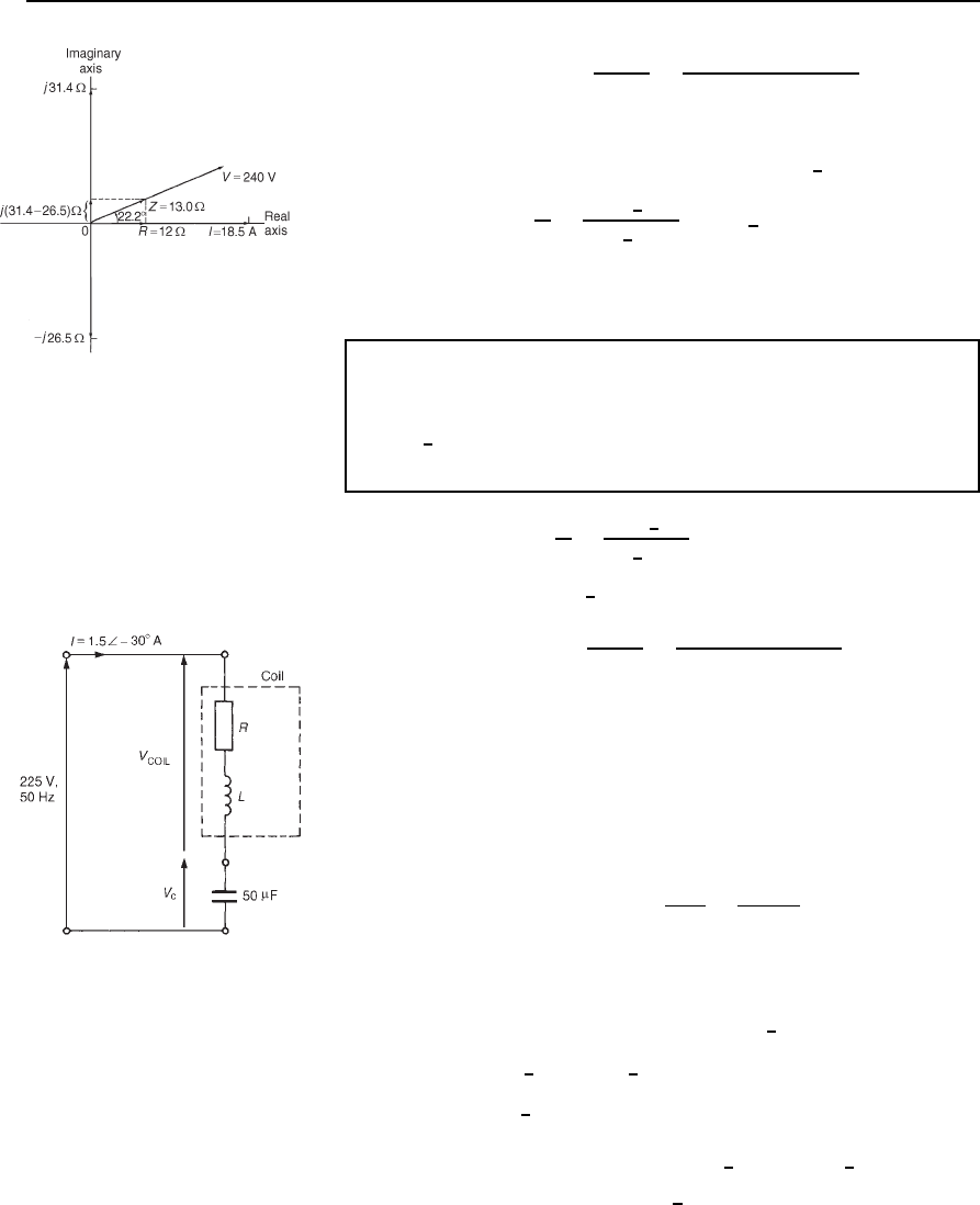
Figure 24.15
Capacitive reactance, X
C
D
1
2fC
D
1
250120 ð 10
6
D 26.5
Impedance Z D R C jX
L
X
C
(see Section 24.2(f))
i.e. Z D 12 C j31.4 26.5 D 12 C j4.9 or 13.0
6
22.2
°
Current flowing, I D
V
Z
D
240
6
0
°
13.0
6
22.2
°
D 18.5
66
−22.2
°
A,
i.e., the current flowing is 18.5 A, lagging the voltage by 22.2
°
.
The phasor diagram is shown on the Argand diagram in Figure 24.15
Problem 11. A coil of resistance R ohms and inductance L henrys
is connected in series with a 50
µF capacitor. If the supply
voltage is 225 V at 50 Hz and the current flowing in the circuit
is 1.5
6
30
°
A, determine the values of R and L. Determine also
the voltage across the coil and the voltage across the capacitor.
Circuit impedance Z D
V
Z
D
225
6
0
°
1.5
6
30
°
D 150
6
30
°
or 129.9 Cj75.0
Capacitive reactance X
C
D
1
2fC
D
1
25050 ð 10
6
D 63.66
Circuit impedance Z D R C jX
L
X
C
i.e. 129.9 C j75.0 D R C jX
L
63.66
Equating the real parts gives: resistance R
= 129.9 Z.
Equating the imaginary parts gives: 75.0 D X
L
63.66,
from which, X
L
D 75.0 C 63.66 D 138.66
Since X
L
D 2fL, inductance L D
X
L
2f
D
138.66
250
D 0.441 H
The circuit diagram is shown in Figure 24.16.
Figure 24.16
Voltage across coil, V
COIL
D IZ
COIL
Z
COIL
D R C jX
L
D 129.9 C j138.66 or 190
6
46.87
°
Hence V
COIL
D 1.5
6
30
°
190
6
46.87
°
D 285
66
16.87
°
V or .272.74 Y j82.71/V
Voltage across capacitor, V
C
D IX
C
D 1.5
6
30
°
63.66
6
90
°
D 95.49
66
−120
°
V or
.
−47.75 − j82.70/V
440 Electrical Circuit Theory and Technology
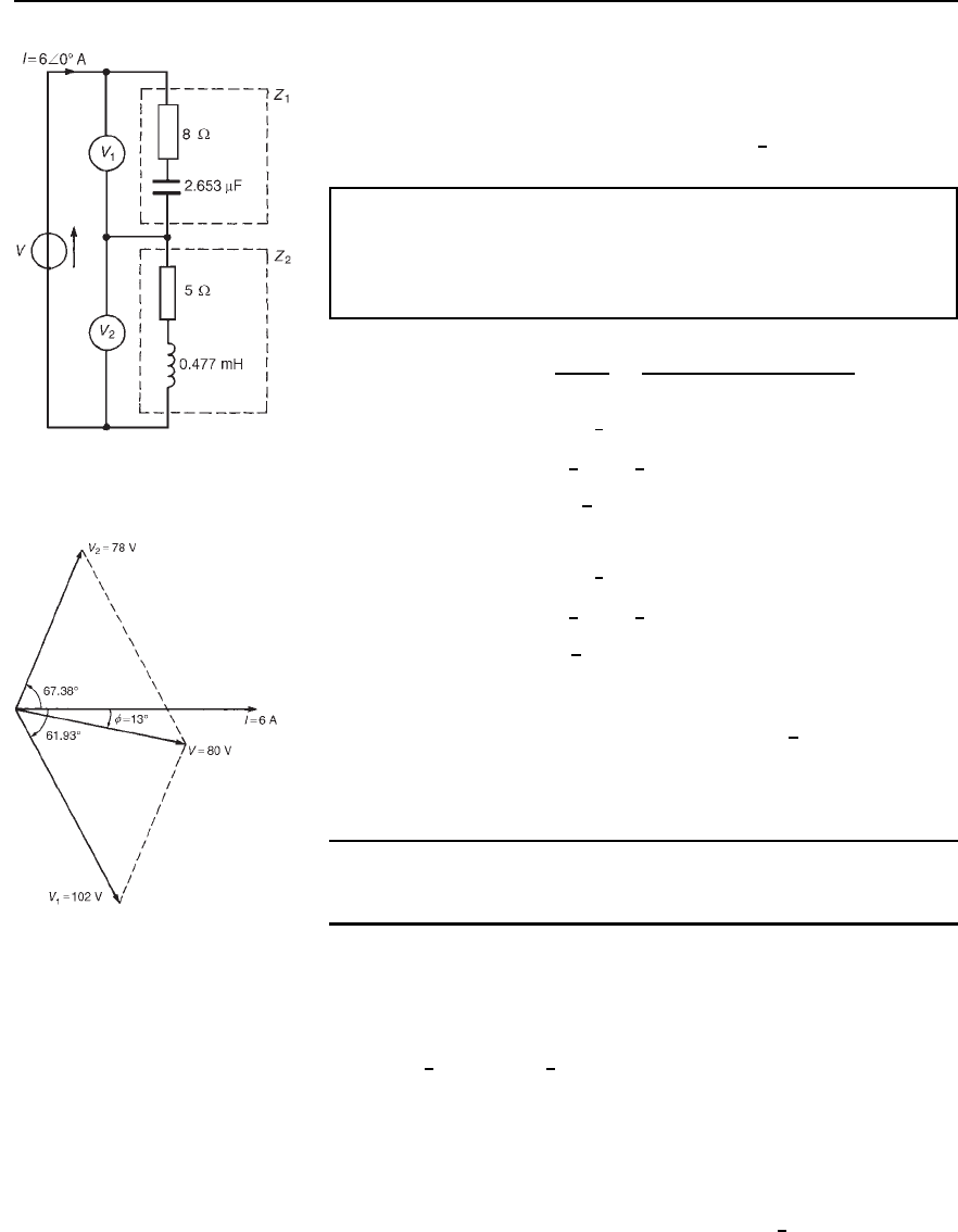
Figure 24.17
[Check: Supply voltage V D V
COIL
C V
C
D 272.74 C j82.71 C 47.75 j82.70
D 225 C j0Vor225
6
0
°
V]
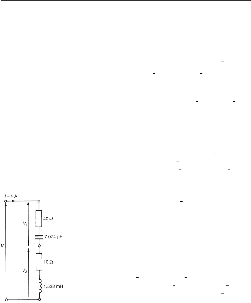
Problem 12. For the circuit shown in Figure 24.17, determine the
values of voltages V
1
and V
2
if the supply frequency is 4 kHz.
Determine also the value of the supply voltage V and the circuit
phase angle. Draw the phasor diagram.
For impedance Z
1
, X
C
D
1
2fC
D
1
240002.653 ð 10
6
D 15
Hence Z
1
D 8 j15 or 17
6
61.93
°
and voltage V
1
D IZ
1
D 6
6
0
°
17
6
61.93
°
D 102
66
−61.93
°
Vor.48 − j90/V
For impedance Z
2
, X
L
D 2fL D 240000.477 ð 10
3
D 12
Hence Z
2
D 5 C j12 or 13
6
67.38
°
and voltage V
2
D IZ
2
D 6
6
0
°
13
6
67.38
°
D 78
66
67.38
°
V or .30 Y j72/V
Supply voltage, V D V
1
C V
2
D 48 j90 C 30 C j72
D .78
− j18/V or 80
66
−13
°
V
Circuit phase angle, f
= 13
°
leading. The phasor diagram is shown in
Figure 24.18.
Figure 24.18
Further problems on the application of complex numbers to series a.c.
circuits may be found in Section 24.3 following, problems 1 to 20.
24.3 Further problems
on series a.c. circuits
1 Determine the resistance R and series inductance L (or capacitance
C) for each of the following impedances, assuming the frequency
to be 50 Hz. (a) 4 C j7 (b) 3 j20 (c) j10 (d) j3k
(e) 15
6
/3 (f) 6
6
45
°
M
[(a) R D 4 , L D 22.3mH(b)R D 3 , C D 159.3
µF
(c) R D 0,L D 31.8mH(d)R D 0,C D 1.061
µF
(e) R D 7.5 , L D 41.3mH
(f) R D 4.243 M, C D 0.750 nF]
2 A 0.4
µF capacitor is connected to a 250 V, 2 kHz supply. Determine
the current flowing. [1.257
6
90
°
Aorj1.247 A]
Application of complex numbers to series a.c. circuits 441
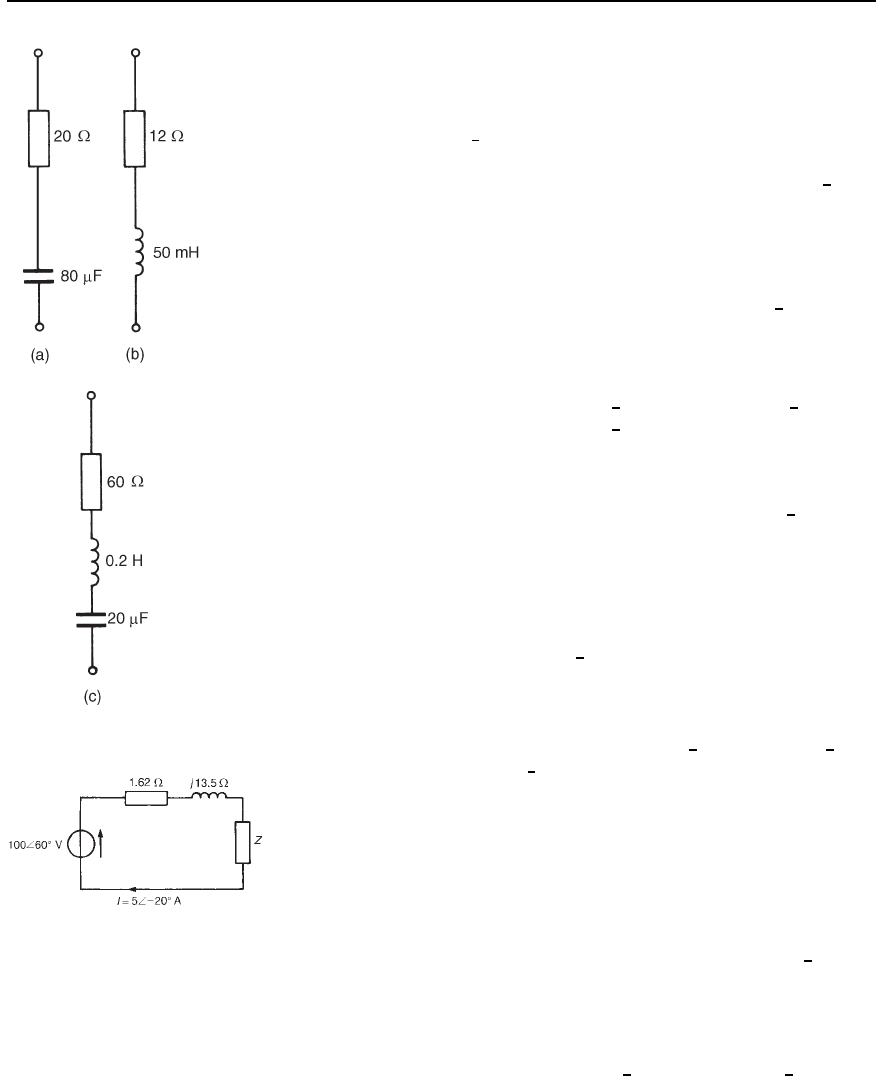
Figure 24.19
3 Two voltages in a circuit are represented by 15 Cj10Vand
12 j4V. Determine the magnitude of the resultant voltage when
these voltages are added. [27.66 V]
4 A current of 2.5
6
90
°
A flows in a coil of inductance 314.2 mH
and negligible resistance when connected across a 50 Hz supply.
Determine the value of the supply p.d. [246.8
6
0
°
V]
5 A voltage 75 C j90V is applied across an impedance and a
current of 5 Cj12A flows. Determine (a) the value of the circuit
impedance, and (b) the values of the components comprising the
circuit if the frequency is 1 kHz.
[(a) Z D 8.61 j2.66 or 9.01
6
17.19
°
(b) R D 8.61 , C D 59.83
µF]
6 Determine, in polar form, the complex impedances for the circuits
shown in Figure 24.19 if the frequency in each case is 50 Hz.
[(a) 44.53
6
63.31
°
(b) 19.77
6
52.62
°
(c) 113.5
6
58.08
°
]
7 For the circuit shown in Figure 24.20 determine the impedance Z in
polar and rectangular forms.
[Z D 1.85 C j6.20 or 6.47
6
73.39
°
]
8A30
µF capacitor is connected in series with a resistance R at a
frequency of 200 Hz. The resulting current leads the voltage by 30
°
.
Determine the magnitude of R. [45.95 ]
9 A coil has a resistance of 40 and an inductive reactance of 75 .
The current in the coil is 1.70
6
0
°
A. Determine the value of (a) the
supply voltage, (b) the p.d. across the 40 resistance, (c) the p.d.
across the inductive part of the coil, and (d) the circuit phase angle.
Draw the phasor diagram.
[(a) 68 Cj127.5 Vor144.5
6
61.93
°
V (b) 68
6
0
°
V
(c) 127.5
6
90
°
V (d) 61.93
°
lagging]
10 An alternating voltage of 100 V, 50 Hz is applied across an
impedance of 20 j30. Calculate (a) the resistance, (b) the
capacitance, (c) the current, and (d) the phase angle between current
and voltage
[(a) 20 (b) 106.1
µF (c) 2.774 A (d) 56.31
°
leading]
11 A capacitor C is connected in series with a coil of resistance R and
inductance 30 mH. The current flowing in the circuit is 2.5
6
40
°
A
when the supply p.d. is 200 V at 400 Hz. Determine the value of
(a) resistance R, (b) capacitance C, (c) the p.d. across C, and (d) the
p.d., across the coil. Draw the phasor diagram.
[(a) 61.28 (b) 16.59
µF
(c) 59.95
6
130
°
V (d) 242.9
6
10.90
°
V]
12 A series circuit consists of a 10 resistor, a coil of inductance
0.09 H and negligible resistance, and a 150
µF capacitor, and is
Figure 24.20
442 Electrical Circuit Theory and Technology
connected to a 100 V, 50 Hz supply. Calculate the current flowing
and its phase relative to the supply voltage.
[8.17 A lagging V by 35.20
°
]
13 A 150 mV, 5 kHz source supplies an ac. circuit consisting of a coil
of resistance 25 and inductance 5 mH connected in series with a
capacitance of 177 nF. Determine the current flowing and its phase
angle relative to the source voltage. [4.44
6
42.31
°
mA]
14 Two impedances, Z
1
D 5
6
30
°
and Z
2
D 10
6
45
°
draw a current
of 3.36 A when connected in series to a certain a.c. supply. Deter-
mine (a) the supply voltage, (b) the phase angle between the voltage
and current, (c) the p.d. across Z
1
, and (d) the p.d. across Z
2
.
[(a) 50 V (b) 40.01
°
lagging (c) 16.8
6
30
°
V (d) 33.6
6
45
°
V]
15 A 4500 pF capacitor is connected in series with a 50
resistor across an alternating voltage
v D 212.1sin10
6
t C /4
volts. Calculate (a) the rms value of the voltage, (b) the circuit
impedance, (c) the rms current flowing, (d) the circuit phase angle,
(e) the voltage across the resistor, and (f) the voltage across the
capacitor.
[(a) 150
6
45
°
V (b) 86.63
6
54.75
°
(c) 1.73
6
99.75
°
A (d) 54.75
°
leading
(e) 86.50
6
99.75
°
V (f) 122.38
6
9.75
°
V]
16 If the p.d. across a coil is 30 C j20V at 60 Hz and the coil consists
of a 50 mH inductance and 10 resistance, determine the value of
current flowing (in polar and cartesian forms).
[1.69
6
28.36
°
A; 1.49 j0.80A]
17 Three impedances are connected in series across a 120 V, 10 kHz
supply. The impedances are:
(i) Z
1
, a coil of inductance 200 µH and resistance 8
(ii) Z
2
, a resistance of 12
(iii) Z
3
, a 0.50 µF capacitor in series with a 15 resistor.
Determine (a) the circuit impedance, (b) the circuit current, (c) the
circuit phase angle, and (d) the p.d. across each impedance.
[(a) 39.95
6
28.82
°
(b) 3.00
6
28.82
°
A (c) 28.82
°
leading
(d) V
1
D 44.70
6
86.35
°
V, V
2
D 36.00
6
28.82
°
V,
V
3
D 105.56
6
35.95
°
V]
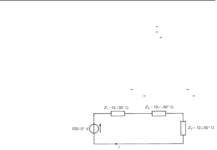
18 Determine the value of voltages V
1
and V
2
in the circuit shown in
Figure 24.21, if the frequency of the supply is 2.5 kHz. Find also
Figure 24.21
Application of complex numbers to series a.c. circuits 443
the value of the supply voltage V and the circuit phase angle. Draw
the phasor diagram.
[V
1
D 164
6
12.68
°
Vor160 j36V
V
2
D 104
6
67.38
°
Vor40 C j96V
V
3
D 208.8
6
16.70
°
Vor200 Cj60V
Phase angle D 16.70
°
lagging]
19 A circuit comprises a coil of inductance 40 mH and resistance 20
in series with a variable capacitor. The supply voltage is 120 V at
50 Hz. Determine the value of capacitance needed to cause a current
of 2.0 A to flow in the circuit. [46.04 F]
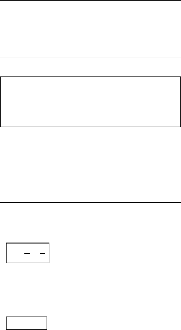
20 For the circuit shown in Figure 24.22, determine (i) the circuit
current I flowing, and (ii) the p.d. across each impedance.
[(i) 3.71
6
17.35
°
A (ii) V
1
D 55.65
6
12.65
°
V,
V
2
D 37.10
6
77.35
°
V,V
3
D 44.52
6
32.65
°
V]
Figure 24.22
25 Application of complex
numbers to parallel a.c.
networks
At the end of this chapter you should be able to:
ž determine admittance, conductance and susceptance in a.c.
circuits
ž perform calculations on parallel a.c. circuits using complex
numbers
25.1 Introduction
As with series circuits, parallel networks may be analysed by using phasor
diagrams. However, with parallel networks containing more than two
branches this can become very complicated. It is with parallel a.c. network
analysis in particular that the full benefit of using complex numbers
may be appreciated. The theory for parallel a.c. networks introduced in
Chapter 16 is relevant; more advanced networks will be analysed in this
chapter using j notation. Before analysing such networks admittance,
conductance and susceptance are defined.
25.2 Admittance,
conductance and
susceptance
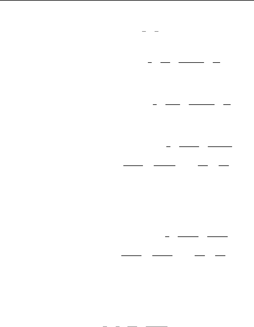
Admittance is defined as the current I flowing in an a.c. circuit divided
by the supply voltage V (i.e. it is the reciprocal of impedance Z). The
symbol for admittance is Y. Thus
Y =
I
V
=
1
Z
The unit of admittance is the Siemen, S.
An impedance may be resolved into a real part R and an imaginary part
X, giving Z D R š jX. Similarly, an admittance may be resolved into two
parts—the real part being called the conductance G, and the imaginary
part being called the susceptance B—and expressed in complex form.
Thus admittance
Y = G ± jB
When an a.c. circuit contains:
Application of complex numbers to parallel a.c. networks 445
(a) pure resistance, then
Z D R and Y D
1
Z
D
1
R
D G
(b) pure inductance, then
Z D jX
L
and Y D
1
Z
D
1
jX
L
D
j
jX
L
j
D
j
X
L
D −jB
L
thus a negative sign is associated with inductive susceptance, B
L
(c) pure capacitance, then
Z DjX
C
and Y D
1
Z
D
1
jX
C
D
j
jX
C
j
D
j
X
C
D YjB
C
thus a positive sign is associated with capacitive susceptance, B
C
(d) resistance and inductance in series, then
Z D R C jX
L
and Y D
1
Z
D
1
R C jX
L
D
R jX
L
R
2
C X
2
L
i.e. Y D
R
R
2
C X
2
L
j
X
L
R
2
C X
L
2
or Y =
R
jZj
2
− j
X
L
jZj
2
Thus conductance, G D R/jZj
2
and inductive susceptance,
B
L
DX
L
/jZj
2
.
(Note that in an inductive circuit, the imaginary term of the
impedance, X
L
, is positive, whereas the imaginary term of the
admittance, B
L
, is negative.)
(e) resistance and capacitance in series, then
Z D R jX
C
and Y D
1
Z
D
1
R jX
C
D
R C jX
C
R
2
C X
2
C
i.e. Y D
R
R
2
C X
2
C
C j
X
C
R
2
C X
2
C
or Y =
R
jZj
2
Y j
X
C
jZj
2
Thus conductance, G D R/jZj
2
and capacitive susceptance,
B
C
D X
C
/jZj
2
.
(Note that in a capacitive circuit, the imaginary term of the
impedance, X
C
, is negative, whereas the imaginary term of the
admittance, B
C
, is positive.)
(f) resistance and inductance in parallel, then
1
Z
D
1
R
C
1
jX
L
D
jX
L
C R
RjX
L
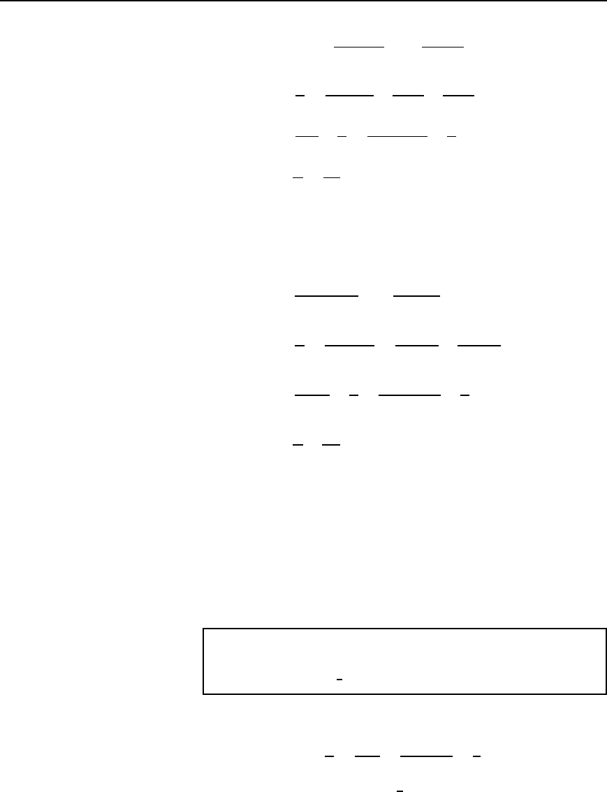
446 Electrical Circuit Theory and Technology
from which, Z =
.R/.jX
L
/
R Y jX
L
i.e.
product
sum
and Y D
1
Z
D
R C jX
L
jRX
L
C
R
jRX
L
C
jX
L
jRX
L
i.e., Y D
1
jX
L
C
1
R
D
j
jX
L
j
C
1
R
or Y
=
1
R
−
j
X
L
Thus conductance, G = 1=R and inductive susceptance,
B
L
= −1=X
L
(g) resistance and capacitance in parallel, then
Z D
RjX
C
R jX
C
i.e.
product
sum
and Y D
1
Z
D
R jX
C
jRX
C
D
R
jRX
C
jX
C
jRX
C
i.e. Y D
1
jX
C
C
1
R
D
j
jX
C
j
C
1
R
or Y
=
1
R
Y
j
X
C
25.1
Thus conductance, G
= 1=R and capacitive susceptance,
B
C
= l=X
C
.
The conclusions that may be drawn from Sections (d) to (g) above
are:
(i) that a series circuit is more easily represented by an impedance,
(ii) that a parallel circuit is often more easily represented by an
admittance especially when more than two parallel impedances are
involved.
Problem 1. Determine the admittance, conductance and suscep-
tance of the following impedances: (a) j5 (b) 25 C j40
(c) 3 j2 (d) 50
6
40
°
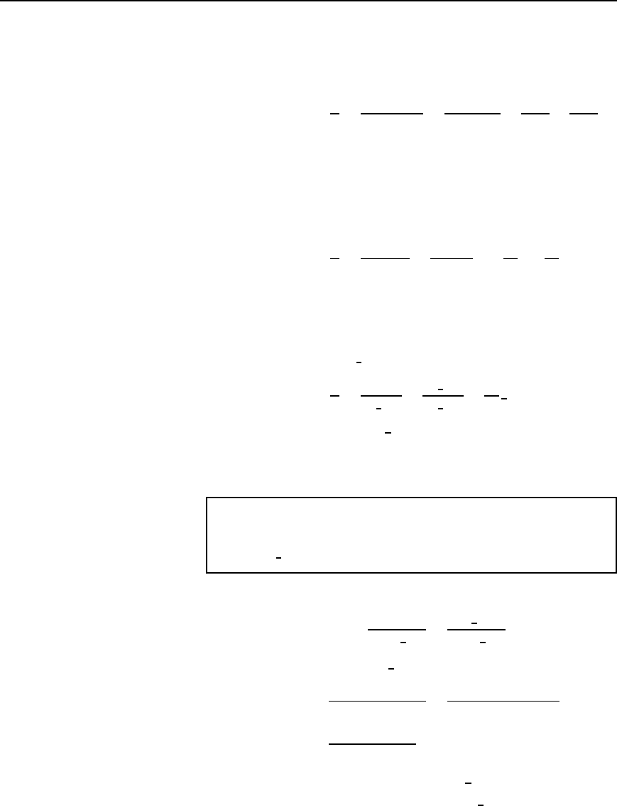
(a) If impedance Z Dj5 , then
admittance Y D
1
Z
D
1
j5
D
j
j5j
D
j
5
D j0.2Sor 0.2
66
90
°
S
Application of complex numbers to parallel a.c. networks 447
Since there is no real part, conductance, G = 0,andcapacitive
susceptance, B
C
= 0.2S
(b) If impedance Z D 25 C j40 then
admittance Y D
1
Z
D
1
25 C j40
D
25 j40
25
2
C 40
2
D
25
2225
j40
2225
D .0.0112
− j0.0180/S
Thus conductance, G
= 0.0112 S and inductive susceptance,
B
L
= 0.0180 S
(c) If impedance Z D 3 j2, then
admittance Y D
1
Z
D
1
3 j2
D
3 C j2
3
2
C 2
2
D
3
13
C j
2
13
S
or .0.231 Y j0.154/S
Thus conductance, G
= 0.231 S and capacitive susceptance,
B
C
= 0.154 S
(d) If impedance Z D 50
6
40
°
, then
admittance Y D
1
Z
D
1
50
6
40
°
D
1
6
0
°
50
6
40
°
D
1
50
6
40
°
D 0.02
66
−40
°
S or .0.0153 − j0.0129/S
Thus conductance, G
= 0.0153 S and inductive susceptance,
B
L
= 0.0129 S
Problem 2. Determine expressions for the impedance of the
following admittances:
(a) 0.004
6
30
°
S(b)0.001 j0.002S (c) 0.05 Cj0.08S
(a) Since admittance Y D 1/Z, impedance Z D 1/Y.
Hence impedance Z D
1
0.004
6
30
°
D
1
6
0
°
0.004
6
30
°
D 250
66
−30
°
Z or .216.5 − j125/Z
(b) Impedance Z D
1
0.001 j0.002
D
0.001 C j0.002
0.001
2
C 0.002
2
D
0.001 C j0.002
0.000005
D .200 Y j400/Z or 447.2
66
63.43
°
Z
(c) Admittance Y D 0.05 C j0.08 S D 0.094
6
57.99
°
S
