Bhushan B. Nanotribology and Nanomechanics: An Introduction
Подождите немного. Документ загружается.

324 Bharat Bhushan
CH A HV IN
CH B HV IN
Oscillator
Transducer
Synchronous
demodulator
Drive-
plate 1
Driveplate 2
d
1
d
2
DC
signal
output
Pickup
electrode
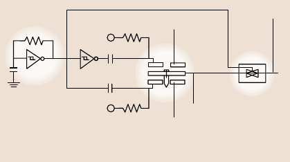
Fig. 8.9. Schematic of
anano/picoindentation sys-
tem with three-plate trans-
ducer with electrostatic ac-
tuation hardware and capaci-
tance sensor [49]
well as in situ imaging, which is most appropriatein nanomechanicalproperty stud-
ies, is used for accurate measurement of hardness with shallow depths [4,11,49].
This nano/picoindentation system is used to make load–displacement measure-
ments and subsequently carry out in situ imaging of the indent, if required. The in-
dentationsystem,shownin Fig.8.9, consistsof a three-platetransducerwith electro-
static actuation hardware used for direct application of normal load and a capacitive
sensor used for measurement of vertical displacement. The AFM head is replaced
with this transducer assembly while the specimen is mounted on the PZT scanner,
which remains stationary during indentation experiments. The transducer consists
of a three (Be
−
Cu) plate capacitive structure and the tip is mounted on the center
plate. The upper and lower plates serveas drive electrodes and the load is applied by
applying appropriate voltage to the drive electrodes. Vertical displacement of the tip
(indentation depth) is measured by measuring the displacement of the center plate
relativeto the two outer electrodes using capacitance technique.The indent area and
consequently hardness value can be obtained from the load–displacementdata. The
Young’s modulus of elasticity is obtained from the slope of the unloading curve.
8.2.7 Localized Surface Elasticity and Viscoelasticity Mapping
Localized Surface Elasticity
Indentation experiments provide a single-point measurement of the Young’s modu-
lus of elasticity calculated from the slope of the indentationcurve during unloading.
Localized surface elasticity maps can be obtained using dynamic force microscopy
in which an oscillating tip is scanned over thesample surface in contactunder steady
and oscillatingload. The lower-frequencyoperationmodes in the kHz range,such as
the force modulationmode [52,54]or the pulsed forcemode [69], arewell suited for
soft samples suchas polymers.However, if thetip–samplecontact stiffness becomes
significantly higher than the cantilever stiffness, the sensitivity of these techniques
strongly decreases. In this case, the sensitivity of the measurement of stiff materials
can be improved by using high-frequency operation modes in the MHz range with
a lateralmotion, suchas acoustic(ultrasonic) forcemicroscopy,referredto as atomic
force acoustic microscopy (AFAM) or contact resonance spectroscopy [55,56,70].
8 Nanotribology, Nanomechanics and Materials Characterization 325
Inclusion of vibration frequencies other than only the first cantilever flexural or tor-
sional resonance frequency, also allows additional information to be obtained.
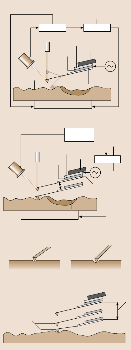
In the negative lift mode force modulation technique, height data is recorded
during primary scanning in the tapping mode, as described earlier. During inter-
leave scanning, the entire cantilever/tip assembly is moved up and down at the
force modulation holder’s bimorph resonance frequency (about 24kHz) at some
amplitude, here referred to as the force modulation amplitude, and the z-direction
feedback control for the sample x–y–z piezo is deactivated, Fig. 8.10a [52,54,57].
During this scanning, height information from the primary scan is used to maintain
a constant lift scan height. This eliminates the influence of height on the measured
signals duringthe interleavescan. Lift scanheight is the mean tip-to-sampledistance
between the tip and sample during the interleave scan. The lift scan height is set such
that the tip is in constant contact with the sample, i.e. a constant static load is ap-
plied. (A higher lift scan height gives a closer mean tip-to-sampledistance.) In addi-
tion, the tip motioncaused by the bimorph vibration resultsin a modulatingperiodic
force. The sample surface resists the oscillations of the tip to a greater or lesser ex-
tent depending upon the sample’s stiffness. The computer records amplitude (which
is a function of the elastic stiffness of the material). Contact analyses can be used
to obtain a quantitative measure of localized elasticity of soft surfaces [54]. Etched
single-crystal silicon cantilevers with integrated tips (force modulation etched Si
probe or DI FESP) with a radius of 25–50nm, a stiffness of 1–5 N/m, and a natural
frequency of 60–100kHz, are commonly used for the measurements. Scanning is
normally set to a rate of 0.5Hz along the fast axis.
In the AFAM technique [55,56,70],the cantilever/tip assembly is moved either
in the normal or lateral mode and the contactstiffness is evaluatedby comparing the
resonance frequency of the cantilever in contact with the sample surface to those of
the free vibrations of the cantilever. Several free resonance frequencies are meas-
ured. Based on the shift of the measured frequencies, the contact stiffness is deter-
mined by solving the characteristic equation for the tip vibrating in contact with the
sample surface. The elastic modulus is calculated from contact stiffness using Hertz
analysis for a spherical tip indenting a plane. Contact stiffness is equal to 8× contact
radius × reduced shear modulus in the shear mode.
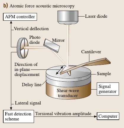
In the lateral mode using the AFAM technique, the sample is glued onto cylin-
drical pieces of aluminum which serve as ultrasonic delay lines coupled to an ultra-
sonic shear wave transducer, Fig. 8.10b [33,55,56]. The transducer is driven with
frequencysweeps to generate in-plane lateral sample surface vibrations. These cou-
ple to the cantilever via the tip–sample contact. To measure torsional vibrations of
the cantilever at frequencies up to 3 MHz, the original electronic circuit of the lat-
eral channel of the AFM (using a low-pass filter with limited bandwidth to a few
hundred kHz) was replaced by a high-speed scheme which bypasses the low-pass
filter. The high-frequencysignal was fed to a lock-in amplifier, digitized using a fast
analogue-to-digital (A/D) card and fed into a broadband amplifier, followed by an
rms-to-dcconverterandreadby a computer.Etched single-crystal silicon cantilevers
(normal stiffness of 3.8–40N/m) integrated tips are used.
326 Bharat Bhushan
Stiff material Compliant material
Tip and cantilever
AFM setting definitions
Lift scan height
a)
Height data
Material 2
Force modulation phase imaging
Sample
x-y controlz control x-y-z piezo
Cantilever
substrate
Laser
Photo-
detector
Material 1
Primary scan: tapping mode
Computer
Amplitude
data
Phase
data
Material 2
Sample
x-y-z control
x-y-z piezo
Canti-
lever
piezo
Substrate
holder
Cantilever
substrate
Laser
Photo-
detector
Material 1
Bimorph
Interleave scan: negative lift mode force modulation
Substrate
holder
Bimorph
2 × force modulation
amplitude
Canti-
lever
piezo
ComputerController
Extender
electronics
Fig. 8.10. (a) Schematic of
force modulation mode used
to obtain amplitude (stiff-
ness) and definitions of force
modulation amplitude and
lift scan height. During pri-
mary scanning, height data
is recorded in tapping mode.
During interleave scanning,
the entire cantilever/tip as-
sembly is vibrated at the bi-
morph’s resonance frequency
and the z-direction feedback
control for the sample x–y–z
piezo is deactivated. During
this scanning, height infor-
mation from the primary scan
is used to maintain a constant
lift scan height. The computer
records amplitude (which is
a function of material stiff-
ness) during the interleave
scan
8 Nanotribology, Nanomechanics and Materials Characterization 327
Fig. 8.10. (b) Schematic of an AFM incorporating shear wave transducer which generates in-
plane lateral sample surface vibrations. Because of the forces between the tip and the surface,
torsionalvibrations of the cantilever are excited[33]. The shift in contact resonance frequency
is a measure of contact stiffness
Viscoelastic Mapping
Another form of dynamic force microscopy, phase contrast microscopy, is used to
detect the contrast in viscoelastic (viscous energy dissipation) properties of the dif-
ferent materials across the surface [53,57–60,71,72]. In these techniques, both de-
flection amplitude and phase angle contrasts are measured, which are measure of
the relative stiffness and viscoelastic properties, respectively. Two phase measure-
ment techniques – tapping mode and torsional resonance (TR) mode – have been
developed, which we now describe.
In the tapping-mode (TM) technique, as described earlier, the cantilever/tip as-
sembly is sinusoidally vibratedat its resonant frequencyand the sample x–y–z piezo
is adjusted using feedback control in the z direction to maintain a constant set point,
Fig. 8.3 [57,58].The feedback signal to the z-direction sample piezo (to keep the set
point constant) is a measure of surface roughness. The extender electronics is used
to measure the phase-angle lag between the cantilever piezo drive signal and the
cantilever response during sample engagement.As illustrated in Fig. 8.3, the phase-
angle lag (at least partially) is a function of the viscoelastic properties of the sample
material. A range of tapping amplitudes and set points can be used for measure-
ments. Commercially etched single-crystal silicon tip (DI TESP) used for tapping
mode, with a radius of 5–10nm, a stiffness of 20–100N/m, and a natural frequency
328 Bharat Bhushan
of 350 to 400kHz, is normally used. Scanningis normally set to a rate of 1Hz along
the fast axis.
In the torsional mode (TR mode), a tip is vibrated in the torsional mode at high
frequency at the resonance frequency of the cantilever beam. Etched single-crystal
silicon cantileverwith integratedtip (DIFESP) with a radius of about 5–10nm, nor-
mal stiffness of 1–5 N/m, torsional stiffness of about 30 times the normal stiffness
and torsional natural frequency of 800 kHz is normally used. A major difference
between the TM and the TR modes is the directionality of the applied oscillation:
a normal (compressive)amplitude exerted for the TM, and a torsional amplitude for
the TR mode. The TR mode is expected to provide good contrast in the tribolog-
ical and mechanical properties of the near surface region as compared to the TM.
Two of the reasons are as follows. (1) In the TM, the interaction is dominated by
the vertical properties of the sample, so the tip spends a small fraction of its time
in the near-field interaction with the sample. Furthermore, the distance between the
tip and the sample changes during the measurements, which changes interaction
time and forces, and affects measured data. In the TR mode, the distance remains
nearly constant. (2) The lateral stiffness of a cantilever is typically about two orders
of magnitude larger than the normal (flexural) stiffness. Therefore, in the TM, if
the sample is relatively rigid, and much of the deformation occurs in the cantilever
beam, whereas in the TR mode, much of the deformation occurs in the sample.
A few comments on the special applications of the TR mode are made next. Since
most of the deformation occurs in the sample, the TR mode can be used to measure
stiff and hard samples. Furthermore, the properties of thin films can be measured
more readily with the TR mode. For both the TM and TR modes, if the cantilever is
drivento vibrate at frequenciesaboveresonance,it would have less motion (highap-
parent stiffness), leading to higher sample deformation and better contrast. It should
be further noted that the TM exerts compressive force, whereas the TR mode exerts
torsional force, therefore normal and shear properties are measured in the TM and
TR modes, respectively.
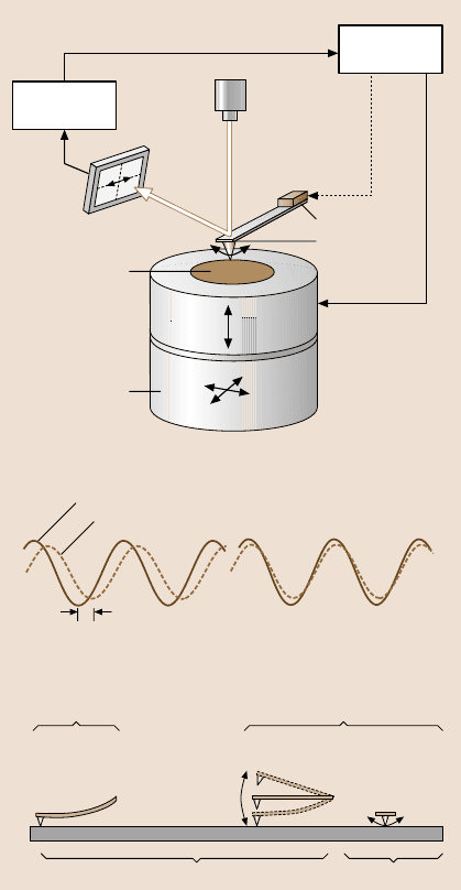
In the TR mode, the torsional vibration of the cantilever beam is achieved using
a specially designed cantilever holder. It is equipped with a piezo system mounted
in a cantilever holder, in which two piezos vibrate out of phase with respect to each
other. A tuning process prior to scanning is used to select the torsional vibration
frequency. The piezo system excites torsional vibration at the cantilever’s resonance
frequency.The torsionalvibrationamplitudeof the tip (TRamplitude)is detected by
the lateral segments of the split-diode photodetector, Fig. 8.11 [59]. The TR mode
measures surface roughness and phase angle as follows. During the measurement,
the cantilever/tip assembly is first vibrated at its resonance at some amplitude de-
pendent upon the excitation voltage, before the tip engages the sample. Next, the tip
engages the sample at some set point. A feedback system coupled to a piezo stage is
used to keep a constant TR amplitude during scanning. This is done by controlling
the vertical position of the sample using a piezo moving in the z direction, which
changes the degree of tip interaction. The displacement of the sample z piezo gives
a roughness image of the sample. A phase-angle image can be obtained by meas-
8 Nanotribology, Nanomechanics and Materials Characterization 329
Diode
laser
Cantilever
Sample
Split-diode
photodetector
Scanner
Tip
Piezo
Feedback loop
TR mode imaging
z
y
x
Cantilever in free air
Cantilever response during engagement
Phase angle
Viscoelastic material Nearly elastic material
Phase angle definition
2 × setpoint
≈10 –
100 nm
DynamicStatic
Contact TM TR mode
Lateral forceVertical force
AFM setting definition
2 × setpoint
≈ 0.3 – 2 nm
Controller
electronics
Detector
electronics
Fig. 8.11. Schematic of tor-
sional resonance mode shown
at the top. Two examples of
the phase-angle response are
shown in the middle.One
is for materials exhibiting
viscoelastic (left)andthe
other nearly elastic properties
(right). Three AFM settings
are compared at the bottom:
contact, tapping mode (TM),
and TR modes. The TR mode
is a dynamic approach with
a laterallyvibratingcantilever
tip that can interact with the
surface more intensively than
other modes. Therefore, more
detailed near-surface infor-
mation is available
uring the phase lag of the cantilever vibration response in the torsional mode during
engagement with respect to the cantilever vibration response in free air before en-
gagement. The control feedback of the TR mode is similar to that of tapping, except
that the torsional resonance amplitude replaces flexural resonance amplitude [59].
Chen and Bhushan [60] have used a variation to the approach just described
(referred to as mode I here). They performed measurements at constant normal can-
tilever deflection (constant load) (mode II) instead of using constant set point in
the Kasai et al. [59] approach. Their approach overcomes the meniscus adhesion
problem present in mode I and reveals true surface properties.
330 Bharat Bhushan
Song and Bhushan [73] presented a forced torsional vibration model for a tip–
cantilever assembly under viscoelastic tip–sample interaction. This model provides
a relationshipof torsionalamplitudeand phase shiftwith lateralcontact stiffness and
viscosity which can be used to extract in-plane interfacial mechanical properties.
Various operating modes of AFM used for surface roughness, localized sur-
face elasticity, and viscoelastic mapping and friction force measurements (to be
discussed later) are summarized in Table 8.2.
8.2.8 Boundary Lubrication Measurements
To study nanoscale boundary lubrication studies, adhesive forces are measured in
the force calibration mode, as previously described. The adhesive forces are also
calculated from the horizontal intercept of curves of friction versus normal load at
zero friction force. For friction measurements, the samples are typically scanned us-
ing an Si
3
N
4
tip overan areaof 2×2µm at a normalload in therange5–130nN. The
samples are generally scanned with a scanrate of 0.5 Hz, which results in a scanning
speed of 2µm/s. Velocity effects on friction are studied out by changing the scan
frequency from 0.1 to 60 Hz, while the scan size is maintained at 2×2µm, which
allows the velocity to vary from 0.4 to 240µm/s. To study the durability proper-
ties, the friction force and coefficient of friction are monitored during scanning at
a normal load of 70nN and a scanning speed of 0.8 µm/s, for a desired number of
cycles [39,40,42].
8.3 Surface Imaging, Friction and Adhesion
8.3.1 Atomic-Scale Imaging and Friction
Surfaceheight imaging downto atomic resolutionof electrically conducingsurfaces
can be carried out using an STM. An AFM can also be used for surface height
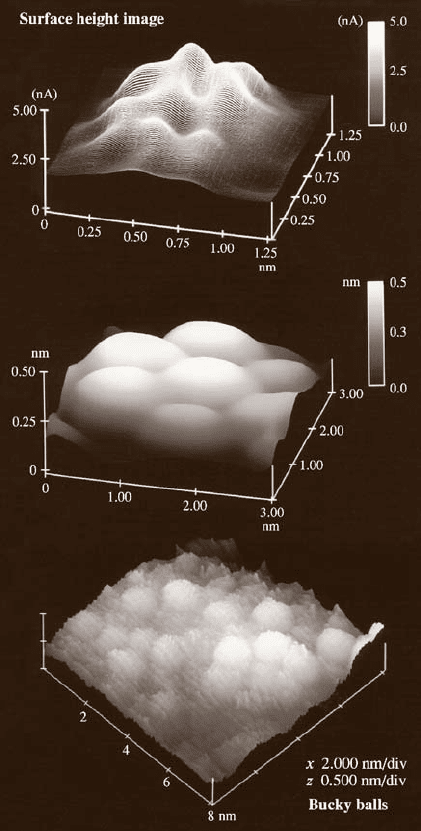
imaging and roughness characterization down to the nanoscale. Figure 8.12 shows
a sequence of STM images at various scan sizes of solvent-deposited C
60
film on
a 200nm thickgold coatedfreshly cleavedmica [74].The film consists ofclustersof
C
60
molecules with a diameter of 8 nm. The C
60
molecules within a cluster appear
to pack in a hexagonal array with a spacing of about 1 nm, however, they do not
follow any long-range order. The measured cage diameter of the C
60
molecule is
about 0.7nm, which is very close to the projected diameter of 0.71nm.
In an AFM measurement during surface imaging, the tip comes into intimate
contact with the sample surface and leads to surface deformation with finite tip–
sample contact area (typically a few atoms). The finite size of the contact area pre-
vents the imaging of individual point defects, and only the periodicity of the atomic
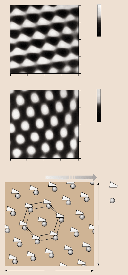
lattice can be imaged. Figure 8.13a shows the topography image of the freshly
cleaved surface of highly oriented pyrolytic graphite (HOPG) [30]. The periodicity
of the graphite is clearly observed.

8 Nanotribology, Nanomechanics and Materials Characterization 331
Table 8.2. Summary of various operating modes of AFM for surface roughness, stiffness, phase angle, and friction
Operating mode Direction
of cantilever
vibration
Vibration frequency
of cantilever (kHz)
Vibration
amplitude (nm)
Feedback control Data obtained
Contact n/a Constant normal load Surface height, friction
Tapping Vertical 350–400 10–100 Set point
(constant tip amplitude)
Surface height, phase angle
(normal viscoelasticity)
Force modulation Vertical 10–20 (bimorph) 10–100 Constant normal load Surface height, amplitude
(normal stiffness)
Lateral Lateral (AAFM) 100–3000 (sample) ≈ 5 (sample) Constant normal load Shift in contact resonance
(normal stiffness, friction)
TR mode I Torsional ≈ 800 0.3–2 Set point
(constant tip amplitude)
Surface height, phase angle
(lateral viscoelasticity)
TR mode II Torsional ≈ 800 0.3–2 Constant normal load Surface height, amplitude
and phase angle (lateral
stiffness and lateral
viscoelasticity)
TR mode III Torsional Higher than 800
in contact
0.3–2 Constant normal load Shift in contact resonance
(friction)
332 Bharat Bhushan
Fig. 8.12. STM images of
solvent-deposited C
60
film on
a gold-coated freshly cleaved
mica at various scan sizes
To study friction mechanisms on an atomic scale, a freshly cleaved HOPG has
been studied by Mate et al. [22] and Ruan and Bhushan [25]. Figure 8.14a shows
the atomic-scale friction force map (raw data) and Fig. 8.13a shows the atomic-
scale topography and friction force maps (after 2D spectrum filtering with high-
frequency noise truncation) [25]. Figure 8.14a also shows a line plot of friction
force profiles along some crystallographicdirection. The actual shape of the friction
profile depends upon the spatial location of axis of tip motion. Note that a por-
tion of the atomic-scale lateral force is conservative. Mate et al. [22] and Ruan and
8 Nanotribology, Nanomechanics and Materials Characterization 333
1.00
0.75
0.50
0.25
0
0 0.25 0.50 0.75 1.00 nm
0.2nm
0.1nm
0.0nm
0.2V
0.1V
0.0V
1.00
0.75
0.50
0
0
0.25
0.75 1.00 nm
0.25
0.50
a)
Topography
Friction
b)
Sliding direction
Topography
Friction
1nm
1nm
Fig. 8.13. (a) Greyscale plots
of surface topography and
friction force maps (2D
spectrum filtered), meas-
ured simultaneously, of
a1nm×1 nm area of freshly
cleaved HOPG, showing the
atomic-scale variation of to-
pography and friction, and (b)
schematic of superimposed
topography and friction maps
from (a); the symbols corre-
spond to maxima. Note the
spatial shift between the two
plots [25]
Bhushan [25] reported that the average friction force increased linearly with normal
load and was reversible with load. Friction profiles were similar during sliding of
the tip in either direction.
During scanning, the tip moves discontinuously over the sample surface and
jumps with discrete steps from one potential minimum (well) to the next. This leads