Bhushan B. Handbook of Micro/Nano Tribology, Second Edition
Подождите немного. Документ загружается.

© 1999 by CRC Press LLC
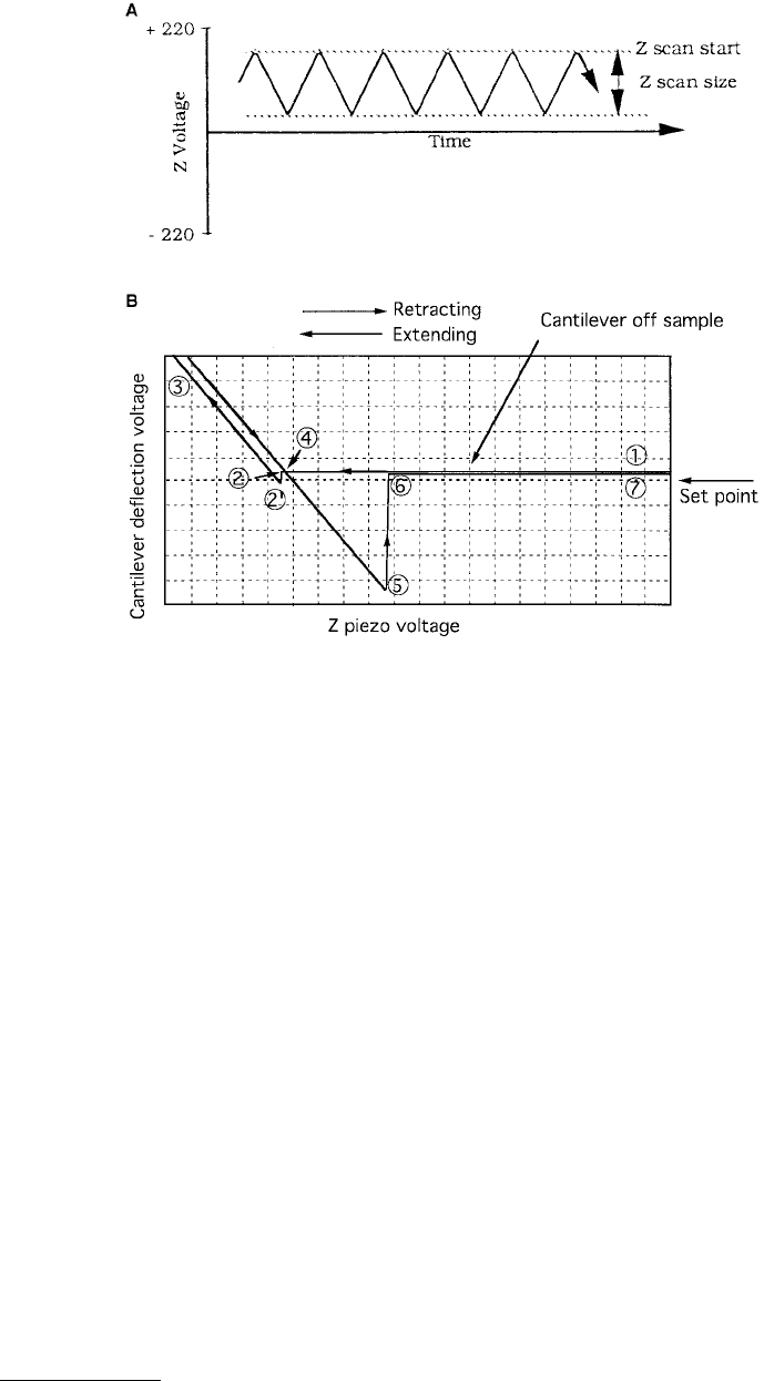
multiplied by the spring constant of the cantilever is the pull-off force, point 2′. As we continue the
forward position of the sample, it pushes the cantilever back through its original rest position (point of
zero applied load) entering the repulsive region (or loading portion) of the force curve. The deflection
signal reaches a maximum at point 3, the maximum piezo extension; then the piezo starts to retract
(unloading portion).
The deflection signal decreases as the piezo and sample retract. Typically, the signal continues to
decrease after the flat, zero deflection point of the force curve. At point 4 the cantilever is not deflected,
but due to adhesion between the tip and the sample, the tip sticks to the sample and the cantilever is
bent down as the piezo continues to retract. Eventually, the spring force of the bent cantilever overcomes
the attractive forces and the cantilever quickly returns to its nondeflected, noncontact position. This is
represented by points 5 and 6 on the example curve. At point 5, the spring force of the cantilever equals
the attractive forces between the tip and the sample. At point 6 the cantilever has returned to its
undeflected state. Then the cantilever deflection signal remains constant as the piezo continues to retract
to point 7. In general, the pull-off force or adhesive force is always greater than the pull-on force. Because
of creep of the piezotube material (lead zirconate titanate) during loading, the tip deflection is not the
same during the extended and retracted mode, which is responsible for the horizontal shift between the
loading and unloading curve. Upon unloading at point 6, the force curve may not return to the original
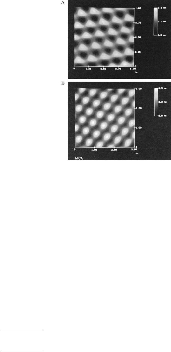
FIGURE 1.20 Typical AFM images of freshly cleaved (A) HOP graphite taken using a square pyramidal Si
3
N
4
tip
(frequency = 41 Hz, normal load = 20 nN, 256 × 256 pixels, original scan size = 10 × 10 nm) and (B) mica
(frequency = 41 Hz, normal load = 12 nN, 256 × 256 pixels, original scan size 4 × 4 nm).*
* Color reproduction follows page 16.
© 1999 by CRC Press LLC
baseline because of thermal drift. By leaving DC power up for 30 min before starting the test, creep effects
can be minimized.
The attractive forces experienced during loading include van der Waals forces (Burnham et al., 1991)
and longer-range forces. A thin layer of liquid, such as condensation of water vapor from ambient air
residing on the surface, will give rise to capillary forces that act to draw the tip and surface together at
small separations (Mate et al., 1989; Blackman et al., 1990; O’Shea et al., 1992; Bhushan and Sundararajan,
1998). In general, any surface absorbate can potentially affect measurements, particularly if they alter the
surface energy of the sample. To minimize liquid-mediated adhesive forces, scanning should be performed
in dry nitrogen with partial pressure of water less than 0.1 Pa to minimize nanometer-scale capillary
condensation (Burnham et al., 1990), or better still, under UHV conditions (Sugawara et al., 1993).
Scanning in the presence of liquid (Marti et al., 1987; Drake et al., 1989; Giles et al., 1993) would also
minimize liquid-mediated adhesion. An imaging technique in water has been developed to study bio-
logical subjects in real environments. For a detailed discussion of forces, see Burnham et al. (1991), Hues
et al. (1993), Burnham and Colton (1993a), and Burnham et al. (1993b).
1.3.2.5.1 Multimode Capabilities
In the multimode, AFM can be used for topography measurements in the “tapping mode,” and for
measurements of lateral (friction) force (to be described later), electric force gradients, and magnetic
force gradients.
In the tapping mode, during scanning over the surface, an oscillating tip slightly taps the surface at
about 300 kHz with a 20- to 100-nm amplitude introduced in the vertical direction with a feedback loop
keeping the average force constant. Oscillation to the cantilever beam is provided by oscillating a bio-
morph mounted on the beam. The oscillating amplitude is kept large enough so that the tip does not
get stuck to the sample because of adhesive attractions. The tapping mode is used in topography
FIGURE 1.21 (A) Force calibration Z waveform and (B) a typical force–separation curve. The force between the
cantilever tip and sample is shown as negative when attractive and positive when repulsive.

© 1999 by CRC Press LLC
measurements to minimize effects of friction and other lateral forces and to measure topography of soft
surfaces. The tapping mode is also referred to as dynamic force microscopy.
The multimode AFM, used with a grounded conducting tip, can measure electric field gradients by
oscillating the tip near its resonant frequency. When the lever encounters a force gradient from the electric
field, the effective spring constant of the cantilever is altered, changing its resonant frequency. Depending
on which side of the resonance curve is chosen, the oscillation amplitude of the cantilever increases or
decreases due to the shift in the resonant frequency. By recording the amplitude of the cantilever, an
image revealing the strength of the electric field gradient is obtained.
In its simplest form, MFM used with a magnetically coated tip detects static cantilever deflection that
occurs when a magnetic field exerts a force on the tip, and the MFM images of magnetic materials can
be produced. Multimode AFM enhances MFM sensitivity by oscillating the cantilever near its resonant
frequency. When the tip encounters a magnetic force gradient, the effective spring constant, and hence
the resonant frequency, is shifted. By driving the cantilever above or below the resonant frequency, the
oscillation amplitude varies as the resonance shifts. An image of magnetic field gradients is obtained by
recording the oscillation amplitude as the tip is scanned over the sample.
Topographic information is separated from the electric field gradients and magnetic field images by
using a so-called lift mode. Measurements in lift mode are taken in two passes over each scan line. On
the first pass, topographical information is recorded in the standard tapping mode where the oscillating
cantilever lightly taps the surface. On the second pass, the tip is lifted to a user-selected separation
(typically 20 to 200 nm) between the tip and local surface topography. By using the stored topographical
data instead of the standard feedback, the separation remains constant without sensing the surface. At
this height, cantilever amplitudes are sensitive to electric field force gradients or relatively weak but long-
range magnetic forces without being influenced by topographic features. Two-pass measurements are
taken for every scan line, producing separate topographic and magnetic force images.
1.3.2.5.2 Electrochemical AFM (ECAFM)
This option allows us to perform electrochemical reactions on the AFM. It includes a potentiostat, a fluid
cell with a transparent cantilever holder and electrodes, and the software required to operate the poten-
tiostat and display the results of the electrochemical reaction.
1.3.2.5.3 Stand-Alone AFM
Digital Instruments, Inc., also manufactures a stand-alone AFM which measures the topography of a
sample with subnanometer resolution regardless of the size of the sample (Anonymous, 1991). The stand-
alone AFM can be placed directly on large samples (larger than about 10 × 10 mm) which cannot be
fitted into the AFM assembly, Figure 1.22. Either the sample must be larger in diameter than the three
support posts or the sample must be rigidly mounted to a larger substrate. Scan lengths of this instrument
are 75 and 125 µm. In these units, the sample is stationary. The cantilever beam and the compact assembly
of laser source and detector are attached to the free end of a piezoelectric transducer, which drives the
tip over the stationary sample, Figure 1.22A and B. Because the cantilever beam and detector assembly
are scanned instead of the sample, some vibration is introduced and lateral resolution of this instrument
is reduced. In the stand-alone AFMs, a single photodetector instead of split photodiode detector is used.
As a result, friction force measurement (to be discussed later) cannot be made.
A cylindrical piezoelectric tube scans a very sharp tip which is mounted on a flexible cantilever over
the sample surface. A compact interferometric detection system mounted on the end of the piezotube
senses the deflection of the cantilever as features in the sample are encountered. In the most common
operating mode, the control system varies the Z-voltage applied to the piezo to keep the cantilever
deflection nearly constant as the tip is scanned over the sample surface in a raster pattern. The variation
in the Z-voltage applied to the piezo translates directly into the variation in height across the sample.
The interference system used to detect cantilever deflection can be made quite compact and therefore
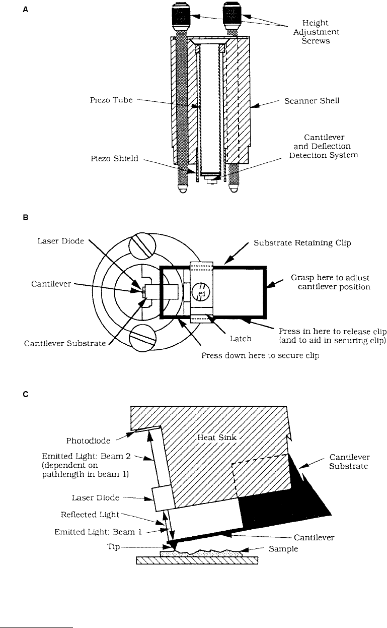
is mounted directly on the piezotube. Figure 1.22C shows the cantilever deflection detection system. The
laser diode emits light from both the top, beam 2, and the bottom, beam 1. The light emitted from the
bottom of the laser is reflected off the cantilever and back into the laser. The reflective cantilever forms
© 1999 by CRC Press LLC
FIGURE 1.22 Schematics of a stand-alone AFM: (A) cross-sectional view, (B) top view, and (C) cantilever deflection
detection system. (From “Stand Alone Atomic Force Microscope, User’s Manual,” Courtesy of Digital Instruments,
Inc., Santa Barbara, CA, 1991.)

© 1999 by CRC Press LLC
an external resonant cavity with the laser. The efficiency of the laser, and hence the intensity of the beam
emitted from the top of the laser, varies according to the phase difference in the light returned from the
external resonant cavity. The phase difference depends on the path length between the cantilever and the
laser diode. Therefore, the light detected by the photodiode provides a measure of the variation in the
path length of the reflected beam. As the cantilever deflects, the path length changes, causing a change
in the signal from the photodiode. Due to the interference between the internal beam and the reflected
beam, the photodiode signal varies sinusoidally with cantilever deflection. The signal from the photodiode
is used to sense the cantilever deflection.
Before the feedback loop can control the cantilever deflection, the tip must be brought into contact
with the sample surface. The three height-adjustment screws control the tip-to-sample spacing. To
facilitate the tip engagement process, the force calibration mode displays the photodiode signal vs. the
Z-position as the piezo is modulated in Z. As the piezo moves the tip up and down, the three height-
adjustment screws are used to bring the tip into contact with the sample. The signal from the photodiode
changes as the tip contacts the surface.
Large-sample AFMs are available which can scan samples as large as 200 × 200
µm without cutting
the sample or touching its surface. In these instruments, the sample is mounted on a motorized X-Y stage.
1.3.2.6 Tip Construction
Now we discuss the various cantilevers and tips used for AFM and FFM (to be described later) studies.
The cantilever stylus used in the AFM/FFM should meet the following criteria: (1) low spring constant
(stiffness); (2) a high resonant frequency; (3) a high mechanical Q; (4) high lateral spring constant
(stiffness); (5) short lever length; (6) incorporation of components (such as mirror) for deflection sensing;
and (7) a sharp protruding tip (Albrecht et al., 1990; Marti and Colchero, 1995). In order to register a
measurable deflection with small forces, the cantilever must flex with a relatively low force (on the order
of few nanonewtons) requiring vertical spring constants of 10
–2
to 10
2
N/m for atomic resolution in the
contact-profiling mode. The data rate or imaging rate in the AFM is limited by the mechanical resonant
frequency of the cantilever. To achieve a large imaging bandwidth, AFM cantilevers should have a resonant
frequency greater than about 10 kHz (preferable is 30 to 100 kHz) in order to make the cantilever the
least sensitive part of the system. Fast imaging rates are not just a matter of convenience, since the effects
of thermal drifts are more pronounced with slow scanning speeds. The combined requirements of a low
spring constant and a high resonant frequency is met by reducing the mass of the cantilever. The
mechanical Q (relative amplitude at the resonant frequency) of the cantilever should have a high value
for some applications. For example, resonance curve detection is a sensitive modulation technique for
measuring small force gradients in noncontact imaging. Increasing the Q increases the sensitivity of the
measurements. Mechanical Q values of 100 to 1000 are typical. In contacting modes, the Q is of less
importance. A high lateral spring constant in the cantilever is desirable to reduce the effect of lateral
forces in the AFM as frictional forces can cause appreciable lateral bending of the cantilever. Lateral
bending results in error in the topography measurements. For friction measurements, cantilevers with
less lateral rigidity are preferred. A sharp protruding tip must be formed at the end of the cantilever to
provide a well-defined interaction with sample over a small area. The tip radius should be much smaller
than the radii of corrugations in the sample in order for these to be measured accurately. The lateral
spring constant depends critically on the tip length. Additionally, the tip should be centered at the free end.
In the past, cantilevers have been cut by hand from thin metal foils or formed from fine wires. Tips
for these cantilevers were prepared by attaching diamond fragments to the ends of the levers by hand,
or in the case of wire cantilevers, electrochemically etching the wire to a sharp point. Several cantilever
geometries for wire cantilevers have been used. The simplest geometry is the L-shaped cantilever, usually
made by bending a wire at a 90° angle. Other geometries include single- and double-V geometries with
a sharp tip attached at the apex of V, and a double-X configuration with a sharp tip attached at the
intersection (Marti et al., 1988; Burnham and Colton, 1989). These cantilevers can be constructed with
high vertical spring constants. For example, a double-cross cantilever with an effective spring constant
of 250 N/m was used by Burnham and Colton (1989). The small size and low mass needed in the AFM
make hand fabrication of the cantilever a difficult process with poor reproducibility. Conventional
© 1999 by CRC Press LLC
microfabrication techniques are ideal for constructing planar thin-film structures which have submicron
lateral dimensions. The triangular (V-shaped) cantilevers have an improved (higher) lateral spring con-
stant in comparison to rectangular cantilevers. The triangular cantilevers are approximately equivalent
to two rectangular cantilevers in parallel (Albrecht et al., 1990). Although the macroscopic radius of a
photolithographically patterned corner is seldom much less than about 50 nm, microscopic asperities
on the etched surface provide tips with near atomic dimensions.
The cantilevers used most commonly for topography measurements are microfabicated silicon nitride
triangular beams with integrated square pyramidal tips made of plasma-enhanced chemical vapor dep-
osition (PECVD) using photolithographic techniques (Albrecht et al., 1990).
2
These are marketed by
Digital Instruments, Inc., Santa Barbara, CA and Park Scientific Instruments, Mountain View, CA. Four
cantilevers with different sizes and spring constants on each cantilever substrate made of boron silicate
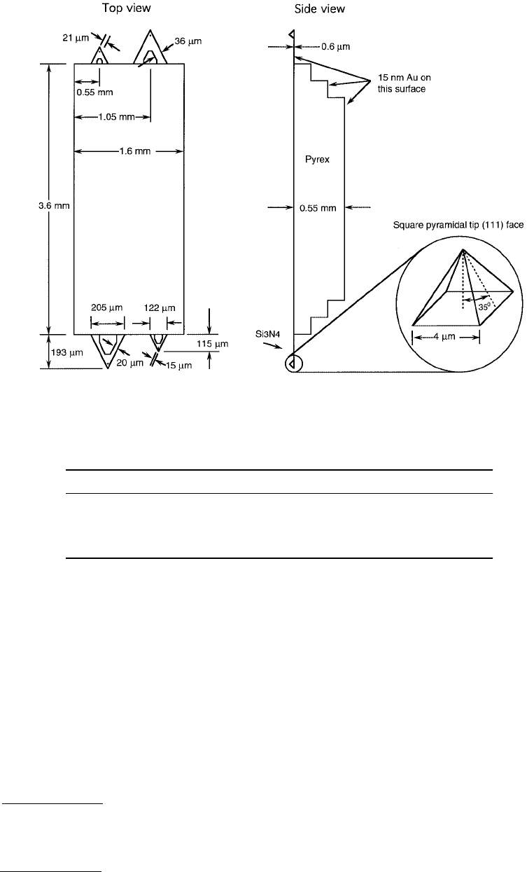
FIGURE 1.23 Schematic of triangular cantilever beam with square pyramidal tips made of PECVD Si
3
N
4
.
TABLE 1.2 Measured Vertical Spring Constants and Natural Frequencies of Triangular
(V-Shaped) Cantilevers Made of PECVD Si
3
N
4
Cantilever Dimension Spring Constant (k
z
), N/m Natural Frequency (ω
0
), kHz
115 µm long, narrow leg 0.38 40
115 µm long, wide leg 0.58 40
193 µm long, narrow leg 0.06 13–22
193 µm long, wide leg 0.12 13–22
Data provided by Digital Instruments, Inc.
2
Some of the best force sensors for magnetic and electrostatic imaging have been made from fine, electrochemically
etched wires. The etched wires have a tapered geometry that varies from about 10 µm in diameter at the point of
attachment to less than 50 nm at the end. The end of the wire may be bent with a knife to form a tip.
© 1999 by CRC Press LLC
glass (Pryex®) are shown in Figure 1.23. Two pairs of the cantilevers on each substrate measure about
115 and 193 µm from the substrate to the apex of the triangular cantilever with base widths of 122 and
205 µm, respectively. Both cantilever legs with the same thicknesses (0.6 µm) of all the cantilevers are
available with wide and narrow legs. Only one cantilever is selected and used from each substrate.
Calculated spring constants and measured natural frequencies for each of the configurations are listed
in Table 1.2. The most commonly used cantilever beam is the 115-µm-long, wide-legged cantilever
(vertical spring constant = 0.58 N/m). Cantilevers with smaller spring constants should be used on softer
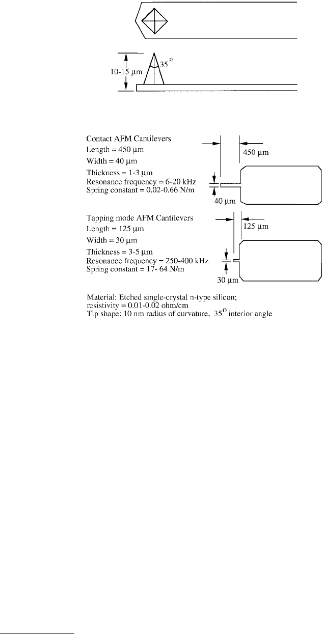
samples. The pyramidal tips are highly symmetric with their ends having a radius of about 20 to 50 nm.
The tip side walls have a slope of 35° and the length of the edges of the tip at the cantilever base is about
4 µm. Ducker et al. (1992) glued a 3.5-µm-radius glass sphere to the free end of the triangular Si
3
N
4
cantilever (with tip removed) for their measurement of colloidal forces. Digital Instruments, Inc., also
markets etched single-crystal, n-type silicon rectangular cantilevers with square pyramidal tips with a
radius of about 10 nm for contact and tapping mode AFMs, Figure 1.24. Spring constants and resonant
frequencies are also presented in Figure 1.24. Park Scientific Instruments markets PECVD Si
3
N
4
rectan-
gular cantilevers with square pyramidal tips with a radius of about 40 nm. Table 1.3A lists the spring
constants and natural frequencies of the beams with their full length used.
Commercial cantilevers have a typical width–thickness ratio of 10:30 which results in 100 to 1000
times stiffer spring constants in the lateral direction compared to the normal direction. Therefore, these
cantilevers are well suited for torsion. For friction measurements, the torsional spring constant should
be minimized in order to be sensitive to the lateral forces. Rather long cantilevers with small thickness
and large tip length are most suitable. Rectangular beams have lower torsional spring constants in
comparison to the triangular (V-shaped) cantilevers. Meyer and Amer (1990b) used a rectangular beam
FIGURE 1.24 Schematic of rectangular cantilever beams with square pyramidal tips made of single-crystal silicon.

© 1999 by CRC Press LLC
made of Si or Si
3
N
4
for topography and friction studies. Table 1.3B lists the spring constants (with full
length of the beam used) in three directions of the typical beams used by them. We note that lateral and
torsional spring constants are about two orders of magnitude larger than the normal spring constants.
Thicker silicon cantilevers made by Digital Instruments, Inc. (Figure 1.24) and Nanosensors GmbH
(Dr. Olaf Wolter), Aidlingen, Germany, are also used for topography and friction measurements. Etched
silicon beams have finer tips compared to those of Si
3
N
4
beams. A cantilever beam required for the
tapping mode is quite stiff and may not be sensitive enough for friction measurements. Meyer et al.
(1992) used a specially designed rectangular silicon cantilever with length = 200 µm, width = 21 µm,
thickness = 0.4 µm, tip length = 12.5 µm, and shear modulus = 50 GPa, giving a normal spring constant
of 0.007 N/m and torsional spring constant of 0.72 N/m, which gives a lateral force sensitivity of 10 pN
and an angle of resolution of 10
–7
rad. With this particular geometry, sensitivity to lateral forces could
be improved by about a factor of 100 compared with commercial V-shaped Si
3
N
4
or rectangular Si or
Si
3
N
4
cantilevers used by Meyer and Amer (1990b) with a torsional spring constant of ~100 N/m. Ruan
and Bhushan (1994a) and Bhushan and Ruan (1994a) used 115-µm-long, wide-legged V-shaped canti-
levers made of Si
3
N
4
for friction measurements.
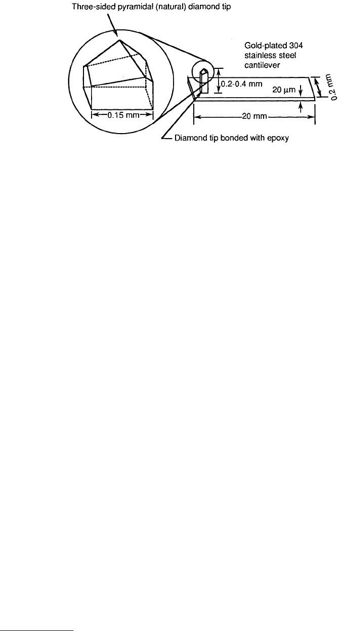
For scratching, wear, and indentation studies, Hamada and Kaneko (1992), Miyamoto et al. (1991,
1993), Bhushan (1994), and Bhushan et al. (1994b–e; 1995a–e, 1997a) have used single-crystal natural
diamond tips ground to the shape of a three-sided pyramid with an apex angle of either 60° or 80° whose
point is sharpened to a radius of about 100 nm (Figure 1.25). The tips are bonded with conductive epoxy
to a gold-plated 304 stainless steel spring sheet (length = 20 mm, width = 0.2 mm, thickness = 20 to
TABLE 1.3(A) Vertical Spring Constants and Natural Frequencies
of Rectangular Beams Made of PECVD Si
3
N
4
Vertical Spring
Constant (k
z
)
(N/m)
Natural
Frequency (ω
0
)
(kHz)
Cantilever Dimensions (µm)
LWT
100 10 0.6 0.08 66
100 20 0.6 0.17 66
100 10 0.3 0.010 33
100 20 0.3 0.021 33
Note: k
z
= EWT
3
/4L
3
, and ω
0
= [k
z
/(m
c
+ 0.24WTLρ)]
1/2
where E is the
Young’s modulus, m
c
is the concentrated mass of the tip, and ρ is the mass
density of the cantilever (Sarid and Elings, 1991). For Si
3
N
4
, E = 150 GPa
and ρ = 3100 kg/m
3
.
Data provided by Park Scientific Instruments.
TABLE 1.3(B) Vertical (k
z
), Lateral (k
y
), and Torsional (k
yT
)
Spring Constants of Rectangular Cantilevers Made of Si
(IBM) and PECVD Si
3
N
4
Dimensions/Stiffness Si Cantilever Si
3
N
4
Cantilever
Length (L), µm 100 100
Width (W), µm1020
Thickness (T), µm 1 0.6
Tip length (l), µm5 3
k
z
, N/m 0.4 0.15
k
y
, N/m 40 175
k
yT
, N/m 120 116
Note: k
z
= EWT
3
/4L
3
, k
y
= EW
3
T/4l
3
, and k
yT
= GWT
3
/3Ll
2
,
where E is Young’s modulus and G is the modulus of rigidity [ =
E/2(1 + ν), where ν is Poisson’s ratio]. For Si, E = 130 GPa and
G = 50 GPa.
From Park Scientific Instruments and Meyer, G. and Amer. N.M.
(1990), Appl. Phys. Lett., 57, 2089–2091. With permission.
© 1999 by CRC Press LLC
60 µm) which acts as a cantilever. Free length of the spring is varied to change the beam stiffness. The
normal spring constant of the beam ranges from about 5 to 600 N/m for a 20-µm-thick beam. The tips
are produced by Advanced Film Technology, Inc., Tokyo. Bhushan (1995) used a spring constant of about
25 N/m for studies of magnetic media.
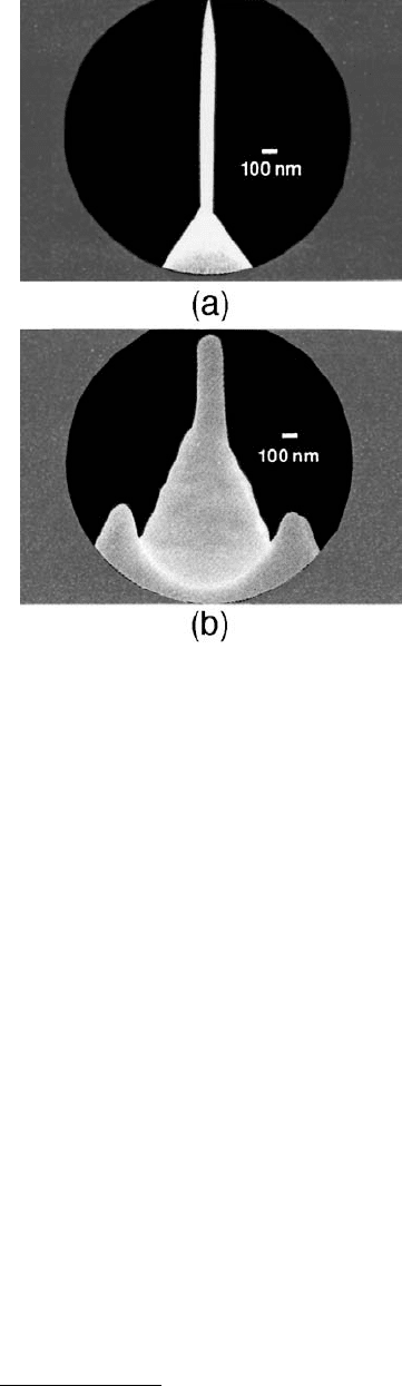
For imaging within trenches by AFM, high-aspect-ratio tips (HART) are used. Examples of the two
probes are shown in Figure 1.26. The HART probes are produced by starting with a conventional Si
3
N
4
pyramidal probe. Through a combination of FIB and high-resolution scanning electron microscopy
(SEM) techniques, a thin filament is grown at the apex of the pyramid. The probe filament is approxi-
mately 1 µm long and 0.1 µm in diameter. It tapers to an extremely sharp point (radius better than the
resolution of most SEMs). The long, thin shape and sharp radius make it ideal for imaging within “vias”
of microstructures and trenches (>0.25 µm). Because of flexing of the probe, it is unsuitable for imaging
structures at the atomic level since the flexing of the probe can create image artifacts. For atomic-scale
imaging, an FIB-milled probe is used that is relatively stiff yet allows for closely spaced topography. These
probes start out as conventional Si
3
N
4
pyramidal probes, but the pyramid is FIB milled until a small cone
shape is formed which has a high aspect ratio that is 0.2 to 0.3 µm in length. The milled probes allow
nanostructure resolution without sacrificing rigidity. These probes are manufactured by Materials Ana-
lytical Services, Raleigh, NC.
Ruger et al. (1992) and Sidles and Rugar (1993) developed a cantilever beam which allowed the
measurements of forces on the order of 10
–16
to 10
–18
N. They used an Si
3
N
4
beam 10 µm in length and
about 20 nm thick with a spring constant of about 10
–5
N/m.
Binh and Garcia (1991, 1992) made nanocantilevers with high resonant frequencies on the order of
tens of kilohertz and a spring constant of around 1 N/m from W and Cu. They produced these with an
extremely thin round cantilever with a spherical tip at its end for measurement of very small van der
Waals forces (Garcia and Binh, 1992). For a cantilever beam radius, cantilever length, and the ball tip
radius of 10, 200, and 150 nm, respectively, made of W, they achieved a resonant frequency of 60 kHz
and a spring constant of 0.3 N/m.
1.3.3 Friction Force Microscope (FFM)
1.3.3.1 Mate et al.’s Design
The first FFM was developed by Mate et al. (1987) at IBM Almaden Research Center, San Jose, CA. In
their setup, the sample was mounted on three orthogonal piezoelectric tubes (25 mm long), two of which
(x-, y-axes) raster the sample in the surface plane with the third (z) moving the sample toward and away
from the tip, Figure 1.27A. A tungsten wire (12 mm long, 0.25 or 0.5 mm in diameter) was used as the
cantilever, one end (the free end) of which was bent at a right angle and was electrochemically etched
in NaOH solution to obtain a sharp point (150 to 300 nm in radius) to serve as the tip. The spring
FIGURE 1.25 Schematic of rectangular cantilever stainless steel beam with three-sided pyramidal natural diamond
tip.
© 1999 by CRC Press LLC
constants were 150 and 2500 N/m for the 0.25- and 0.5-mm-diameter wires, respectively. A laser beam
was used to monitor cantilever deflection in the lateral direction. A light beam was focused on the edge
of the lever by a microscope objective. The interference pattern between the reflected and the reference
beams reflected from the tungsten wire and an optical flat was projected on a photodiode to measure
the instantaneous deflection of the lever. Normal force was approximated by using a calibrated piezo-
electric tube extension. The force was determined by multiplying the cantilever deflection by the spring
constant of the cantilever in the lateral direction. Later, Erlandsson et al. (1988b) used two independent
laser beams to monitor cantilever deflections in the normal and lateral directions to measure normal
and friction forces, Figure 1.27B. They included another laser beam in the lateral direction (Figure 1.27B)
to their original AFM design shown in Figure 1.13. Mate et al. (1987) measured the friction of a tungsten
tip sliding against a freshly cleaved HOP graphite by pushing the tip against the sample in the z-direction
at desired loads (ranging from 7.5 to 56 µN) by moving the sample back and forth parallel to the surface
plane at a velocity of 40 nm/s, and repeating the scanning by stepping the sample (for three-dimensional
profiling). Erlandsson et al. (1988b) measured the atomic-scale friction of muscovite mica. Germann
et al. (1993) measured the atomic-scale friction of diamond surfaces.
1.3.3.2 Kaneko et al.’s Design
The second type of FFM was developed by Kaneko and his co-workers (Kaneko, 1988; Kaneko et al.,
1991). Their earlier design is shown in Figure 1.28 (Kaneko, 1988). A diamond tip was held by a parallel-
leaf spring unit (length = 10 mm, width = 1 mm, thickness = 20 µm, spring constant = 3N/m). The
sample was mounted on another Parallel-leaf spring unit (length = 10 mm, width = 3 mm, thickness =
20 to 30 µm, spring constant 9 to 30 N/m). These parallel-leaf springs have greater torsional rigidity than
single-leaf springs with the same spring constants. Thus deflection errors caused by tip movement are
reduced by using parallel-leaf springs (Miyamoto et al., 1990). A piezoelectric tripod (16 µm stroke at
100 V) was used for loading the sample against the tip as well as moving it in the two directions in the
sample plane. A focusing error-detection-type optical head (resolution <1 nm) was used to measure the
FIGURE 1.26 Schematics of (a) HART Si
3
N
4
probe and
(b) FIB-milled Si
3
N
4
probe.