Bhushan B. Handbook of Micro/Nano Tribology, Second Edition
Подождите немного. Документ загружается.

© 1999 by CRC Press LLC
the coefficient of friction which then can be used to convert the friction profile to the coefficient of
friction profile. Thus any directionality and local variations in friction can be easily measured. In this
method, since topography data are not affected by friction, accurate topography data can be measured
simultaneously with friction data and a better localized relationship between the two can be established.
1.3.3.5.2 Normal Force and Friction Force Calibrations
Based on Ruan and Bhushan (1994a), we now discuss normal force and friction force calibrations. In
order to calculate the absolute value of normal and friction forces in newtons using the measured AFM
and FFM
T
voltage signals, it is necessary to first have an accurate value of the spring constant of the
cantilever (k
c
). The spring constant can be calculated using the geometry and the physical properties of
the cantilever material (Albrecht et al., 1990; Meyer and Amer, 1990b; Sarid and Elings, 1991). However,
the properties of the PECVD Si
3
N
4
(used in fabricating cantilevers) could be different from those of bulk
material. For example, by using an ultrasonic measurement, we found the Young’s modulus of the
cantilever beam to be about 238 ± 18 GPa, which is less than that of bulk Si
3
N
4
(310 GPa). Furthermore,
the thickness of the beam is nonuniform and difficult to measure precisely. Because the stiffness of a
beam goes as the cube of thickness, minor errors in precise measurements of thickness can introduce
substantial stiffness errors. Thus one should experimentally measure the spring constant of the cantilever.
Cleveland et al. (1993) measured the normal spring constant by measuring resonant frequencies of the
beams.
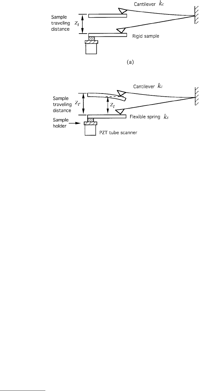
For normal spring constant measurement, we used a stainless steel spring sheet of known stiffness
(width = 1.35 mm, thickness = 15 µm, free hanging length = 5.2 mm) (Ruan and Bhushan, 1994a). One
end of the spring was attached to the sample holder and the other end was made to contact with the
cantilever tip during the measurement, see Figure 1.36. We measured the piezo traveling distance for a
given cantilever deflection. For a rigid sample (such as diamond), the piezo traveling distance Z
t
(measured
from the point where the tip touches the sample) should equal the cantilever deflection. To keep the
cantilever deflection at the same level using a flexible spring sheet, the new piezo traveling distance Z
t′
.
would be different from Z
t
. The difference between Z
t′
. and Z
t
corresponds to the deflection of the spring
sheet. If the spring constant of the spring sheet is k
s
, the spring constant of the cantilever k
c
can be
calculated by
FIGURE 1.36 Illustration showing the deflection of cantilever as it is pushed by (a) a rigid sample or by (b) a
flexible spring sheet. (From Ruan, J. and Bhushan, B. (1994), ASME J. Tribol., 116, 378–388. With permission.)
© 1999 by CRC Press LLC
or
(1.8)
The spring constant of the spring sheet (k
c
) used in this study is calculated to be 1.54 N/m. For a wide-
legged cantilever used in our study (length = 115 µm, base width = 122 µm, leg width = 21 µm, and
thickness = 0.6 µm), k
c
was measured to be 0.40 N/m instead of 0.58 N/m reported by its manufacturer,
Digital Instruments Inc. To relate photodiode detector output to the cantilever deflection in nanometers,
we used the same rigid sample to push against the AFM tip. Because in a rigid sample the cantilever
vertical deflection equals the sample traveling distance measured from the point where the tip touches
the sample, the photodiode output as the tip is pushed by the sample can be converted directly to
cantilever deflection. For our measurements, we found the conversion to be 20 nm/V.
The normal force applied to the tip can be calculated by multiplying the cantilever vertical deflection
by the lever spring constant for samples which have very small adhesive force with the tip. If the adhesive
force between the sample and the tip is large, it should be included in the normal force calculation. This
is particularly important in atomic-scale force measurement because in this region, the typical normal
force that we measure is in the range of a few hundred nanonewtons to a few millinewtons. The adhesive
force could be comparable to the applied force. The magnitude of the adhesive force is determined by
multiplying the maximum cantilever deflection in the downward direction before the tip is pulled off
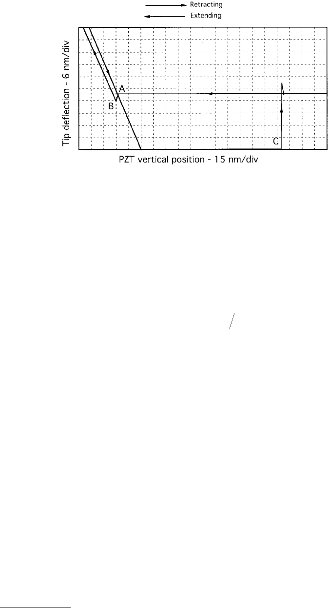
the sample surface by the spring constant of the cantilever. Figure 1.37 shows an example of cantilever
deflection as a function of sample position (height). “Extending” means the sample is pushed toward
the tip, and “retracting” means the sample is pulled away from the tip. As the sample surface approaches
the tip within a few nanometers (point A), an attractive force exists between the atoms of the tip surface
and the atoms of the sample surface. The tip is pulled toward the sample and the contact occurs at point
B. As the sample is pushed further against the tip, the force at the interface increases and the cantilever
is deflected upward. This deflection equals the sample traveling distance measured from point B for a
FIGURE 1.37 Displacement curve of the cantilever tip as it is pushed toward (extending) and pulled away from
(retracting) a silicon sample in measurements made in the ambient environment. The large separation between point
B where the tip is touching the sample and point C where the tip is pulled off the sample is due to a large pull-off
(adhesive) force between the tip and the sample. (From Ruan, J. and Bhushan, B. (1994), ASME J. Tribol., 116,
378–388. With permission.)
ZZkZk
ttstc
′
−
()
=
kkZ ZZ
cst t t
=−
()
′

© 1999 by CRC Press LLC
rigid sample. As the sample is retracted, the force is reduced. At point C in the retracting curve, the
sample is disengaged from the tip. Before the disengagement, the tip is pulled downward due to the
attractive force. The force that is required to pull the tip away from the sample is the force that equals
(but in the opposite direction) the adhesive force. This force is calculated by the maximum cantilever
deflection in the downward direction times the spring constant of the cantilever. The maximum cantilever
deflection in downward direction is just the horizontal distance between points B and C in this curve.
We measured this distance to be about 200 nm in this curve, which corresponds to an adhesive force of
80 nN for a spring constant of 0.4 N/m. Friction force at a zero cantilever deflection is associated with
this force between the sample and the tip. Because the calculation of both the externally applied and
adhesive forces involves the same spring constant of the cantilever, the total normal force (once the sample
and the tip are in contact) is equal to the spring constant times the cantilever “deflection” measured right
before the pull-off point in the retracting curve. This “deflection” is also the piezo traveling distance
measured from point C toward the tip for a rigid sample. Although the calculation of adhesive force is
important in the calculation of normal force, it is not important in the calculation of the coefficient of
friction if we take the slope of friction force vs. normal force curve.
The conversion of the friction signal (from FFM
T
to friction force) is not as straightforward. For
example, one can calculate the degree of twisting for a given friction force using the geometry and the
physical properties of the cantilever (Meyer and Amer, 1988; O’Shea et al., 1992). One would need the
information on the detectors such as the quantum efficiency of the detector, the laser power, the instru-
ment gain, etc. in order to be able to convert the signal into the degree of twisting. Generally speaking,
this procedure cannot be accomplished without having some detailed information about the instrument.
This information is not usually provided by the manufacturers. Even if this information is readily
available, errors may still occur in using this approach because there will always be variations as a result
of the instrumental setup. For example, it has been noticed that the measured FFM
T
signal could be
different for the same sample when different AFM microscopes of the same kind are used. The essence
is that one cannot calibrate the instrument experimentally using this calculation. O’Shea et al. (1992)
did perform a calibration procedure in which the torsional signal was measured as the sample is displaced
a known distance laterally while ensuring that the tip does not slide over the surface. However, it is
difficult to verify that the tip sliding does not occur.
Apparently, a new method of calibration is required. There is a more direct and simpler way of doing
this. The first method described (method 1) to measure friction can directly provide an absolute value
of the coefficient of friction. It can therefore be used just as an internal means of calibration for the data
obtained using method 2 or for a polished sample which introduces least error in friction measurement
using method 1. Method 1 can be used to obtain calibration for friction force for method 2. Then this
calibration can be used for measurement on all samples using method 2. In method 1, the length of the
cantilever required can be measured using an optical microscope; the length of the tip can be measured
using an SEM. The relative angle between the cantilever and the horizontal sample surface can be
measured directly. Thus, the coefficient of friction can be measured with few unknown parameters. The
friction force can then be calculated by multiplying the coefficient of friction by the normal load. The
FFM
T
signal obtained using method 2 can then be converted into friction force. For our instrument, we
found the conversion to be 8.6 nN/V.
1.3.3.5.3 Typical Friction Data
Ruan and Bhushan (1994a) measured the friction of Pt (calibration grid with 10 × 10 µm grid dimension
from Digital Instruments, Inc., with rms roughness of 0.22 nm over 1-mm
2
area), single-crystal silicon
(rms roughness of 0.14 nm over 1-µm
2
area), polished natural diamond (IIa); (rms roughness of 2.3 nm
over 1-µm
2
area), and HOP graphite against an Si
3
N
4
tip using both methods 1 and 2. An engineering
material Al was also measured for reference. Samples were ultrasonically cleaned in alcohol and dried
for a few hours before measurement. The result on Pt (measured using both methods 1 and 2) is used
to calibrate the friction data of other samples obtained using method 2. These data were compared with
© 1999 by CRC Press LLC
those obtained using method 1 for each sample (except graphite and aluminum) to examine the consis-
tency between these two methods.
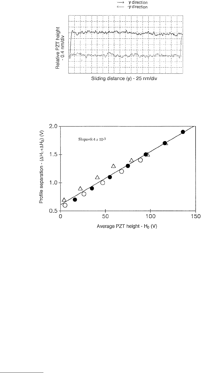
We first show in Figure 1.38 an example of a typical trajectory of the piezo vertical height as the AFM
tip is scanned in both the y- and –y-directions across a Pt surface. For a smooth sample like this, the
separation between these two trajectories can easily be measured. We have measured the height difference
of the piezo (∆H
1
+ ∆H
2
) at different normal loads (H
0
), and used ∆ (∆H
1
+ ∆H
2
) and ∆(H
0
) in
Equation 1.5 to calculate µ. Figure 1.39 shows the data from three sets of measurements at various loads
on Pt. The horizontal axis is the center position of the piezo scanner and the vertical axis is the average
(over a 1-mm scan length) height difference of the piezo between the y and –y scans. During the
measurement, the piezotube center position is changed by setting the [(T – B)/(T + B)] signal at different
values for the feedback circuit. The resulting height difference of the piezotube between the two scans
FIGURE 1.38 A typical profile of the piezo height as a Pt sample is scanned back and forth in the y- and –y-
directions. The normal load is about 50 nN. The cantilever stiffness is 0.4 N/m. (From Ruan, J. and Bhushan, B.
(1994), ASME J. Tribol., 116, 378–388. With permission.)
FIGURE 1.39 The vertical height difference (separation of the surface profile, ∆H
1
+ ∆H
2
) as a function of the
piezo center position (piezo height H
0
) between the two traveling directions (y and –y) of a Pt sample. The three
symbols represent three sets of repeated measurements. The slope of the linear fit is proportional to the coefficient
of friction between the Si
3
N
4
tip and Pt. (From Ruan, J. and Bhushan, B. (1994), ASME J. Tribol., 116, 378–388. With
permission.)
© 1999 by CRC Press LLC
(y and –y) was measured and averaged over the scan length. We see in Figure 1.30 that all data fall closely
on a straight line. The slope (best linear fit) of this curve is 9.4 × 10
–3
. Using the geometry of the cantilever
and the tip and attitude of the cantilever with respect to the sample (L = 115 mm, l = 10 mm in
Equation 1.4), a value of the coefficient of friction of 0.054 is obtained.
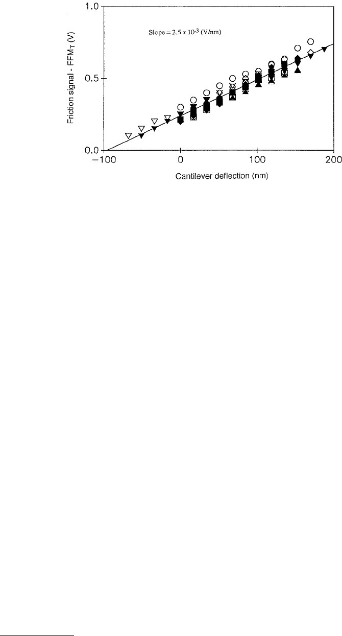
Figure 1.40 is obtained for Pt using method 2. Here, the cantilever vertical deflection vs. the friction
signal (half of the difference of the FFM signals between the x- and –x-scans, or FFM
T
(x) signal) is
plotted. The sample was moved in the x- and –x-direction at a velocity of 4 µm/s and slowly stepped (by
4 nm/step) in the y-direction (16 nm/s) to scan the whole area (1 × 1 µm). The data (averaged over the
scan area) for each measurement can be fitted into a straight line. To show the statistical variation between
different measurements, 11 sets of measurements at various loads were made and were plotted in this
figure. Again, a good linear fit of the data has been observed with a slope of 2.5 mV/nm. Using the value
of the coefficient of friction calculated previously, we calculate that a slope of 1 mV/nm in this curve
corresponds to a coefficient of friction 0.022. Using the spring constant of the cantilever (0.4 N/m), we
then calculated that 1 V in this curve (FFM
T
signal) corresponds to a friction force of 8.6 nN.
Ruan and Bhushan (1994a) made similar measurements on silicon and diamond. They used the values
obtained above for Pt, and the slopes of the curves of these two samples (silicon and diamond) obtained
using method 2 to calculate their coefficient of friction. The data were compared with those obtained
directly using method 1 for the corresponding samples. For simplicity, we summarize the result in
Ta bl e 1.4. A reasonable agreement between the measurements using the two methods was obtained.
Friction data for graphite and aluminum are also included in Table 1.4. (For graphite data, also see Ruan
and Bhushan, 1994b–c.) Method 1 was not used for these samples since a good agreement has already
been obtained between methods 1 and 2 using other samples. In addition, the aluminum sample was
not polished and had a rough surface. Method 1 is difficult to apply to this sample. The friction force
for all tips against graphite was so small that it could not be directly measured using method 1. Even
with method 2, we found that the signal variation at different applied normal forces was also within the
range of experimental uncertainty. The slope that best fits to the data with an uncoated tip is 3 × 10
–4
(V/nm), which corresponds to a coefficient of friction 0.006. This value is listed in Table 1.4. (The
coefficient of friction of graphite against a tungsten tip was reported to be 0.012, according to Mate et al.,
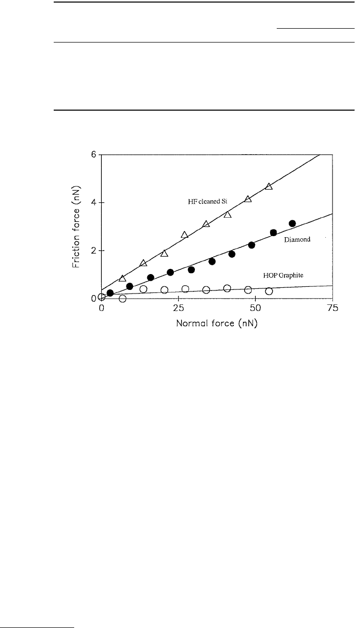
1987). Friction force vs. normal force plots for diamond, HF-cleaned silicon, and graphite are shown in
Figure 1.41.
FIGURE 1.40 Friction signal as a function of cantilever vertical deflection for Pt. Different symbols represent 11
sets of repeated measurements. The slope of the linear fit is proportional to the coefficient of friction between the
Si
3
N
4
tip and Pt. Vertical cantilever vertical spring constant is 0.4 N/m with conversion of AFM signal to be 20 nm/V
and the FFM (friction) signal is 8.6 nN/V. (From Ruan, J. and Bhushan, B. (1994), ASME J. Tribol., 116, 378–388.
With permission.)
© 1999 by CRC Press LLC
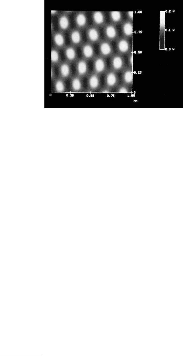
Figure 1.42 shows atomic-scale friction profiles of freshly cleaved HOP graphite. It is clearly seen that
the friction profile exhibits the periodicity of the graphite surface structure (Figure 1.20A). However, the
high points in the topography and the high friction points are shifted relative to each other (Ruan and
Bhushan, 1994b).
1.3.4 Surface Force Apparatus
SFAs are used to study both static and dynamic properties of the molecularly thin liquid films sandwiched
between two molecularly smooth surfaces. The SFAs were originally developed by Tabor and Winterton
(1969) and later by Israelachvili and Tabor (1972) to measure van der Waals forces between two mica
surfaces as a function of separation in air or vacuum. Israelachvili and Adams (1978) developed a more-
advanced apparatus to measure normal forces between two surfaces immersed in a liquid so thin that
their thickness approaches the dimensions of the liquid molecules themselves. A similar apparatus was
also developed by Klein (1980). The SFAs, originally used in studies of adhesive and static interfacial
forces, were first modified by Chan and Horn (1985) and later by Israelachvili et al. (1988) and Klein
et al. (1991) to measure the dynamic shear (sliding) response of liquids confined between molecularly
smooth optically transparent mica surfaces. Optically transparent surfaces are required because the
surface separation is measured using an optical interference technique. Van Alsten and Granick (1988)
and Peachey et al. (1991) developed a new friction attachment which allows for the two surfaces to be
TABLE 1.4 Roughness and Microscale Friction Data of Various Samples
Coefficient of Friction
FFM Measurements
Sample Roughness
a
(nm) Method 1 Method 2
Platinum 0.22 0.05 0.05
Single-crystal silicon (HF cleaned) 0.14 0.07 0.08
Single-crystal silicon (before HF cleaning) 0.14 0.06 0.06
Polished natural diamond (IIa) 2.3 0.04 0.05
HOP graphite 0.09 ~0.006
Aluminum 40 0.08
a
Root mean square value measured over a 1 × 1 µm area using AFM.
FIGURE 1.41 Friction force as a function of normal force for an Si
3
N
4
tip sliding against silicon, diamond, and
graphite. (From Ruan, J. and Bhushan, B. (1994), ASME J. Tribol., 116, 378–388. With permission.)
© 1999 by CRC Press LLC
sheared past each other at varying sliding speeds or oscillating frequencies while simultaneously mea-
suring both the friction force and normal force between them. Israelachvili (1989) and Luengo et al.
(1997) have also presented modified SFA designs for dynamic measurements at oscillating frequencies.
Because the mica surfaces are molecularly smooth, the actual area of contact is well defined and mea-
surable, and asperity deformation does not complicate the analysis. During sliding experiments, the area
of parallel surfaces is very large compared to the thickness of the sheared film and this provides an ideal
condition for studying shear behavior, because it permits one to study molecularly thin liquid films whose
thickness is well defined to the resolution of an angstrom. Molecularly thin liquid films cease to behave
as a structural continuum with properties different from that of the bulk material (Van Alsten and
Granick, 1988, 1990b; Homola et al., 1989; Gee et al., 1990; Granick, 1991).
Tonck et al. (1988) and Georges et al. (1993) developed an SFA used to measure the static and dynamic
forces (in the normal direction) between a smooth fused borosilicate glass against a smooth and flat
silicon wafer. They used the capacitance technique to measure surface separation; therefore, use of
optically transparent surfaces was not required. Among others, metallic surfaces can be used at the
interface. Georges et al. (1994) modified the original SFA so that a sphere can be moved toward and away
from a plane and can be sheared at constant separation from the plane, for interfacial friction studies.
For a detailed review of various types of SFAs, see Israelachvili (1989, 1991), Horn (1990), and Homola
(1993). SFAs based on their design are commercially available from Anutech Pte Ltd., GPO Box 4,
Canberra, Australia 2601.
1.3.4.1 Israelachvili’s and Granick’s Design
The following review is primarily based on the papers by Israelachvili (1989) and Homola (1993).
Israelachvili et al.’s design, later followed by Granick et al., for oscillating shear studies is most commonly
used by researchers around the world.
1.3.4.1.1 Classical SFA
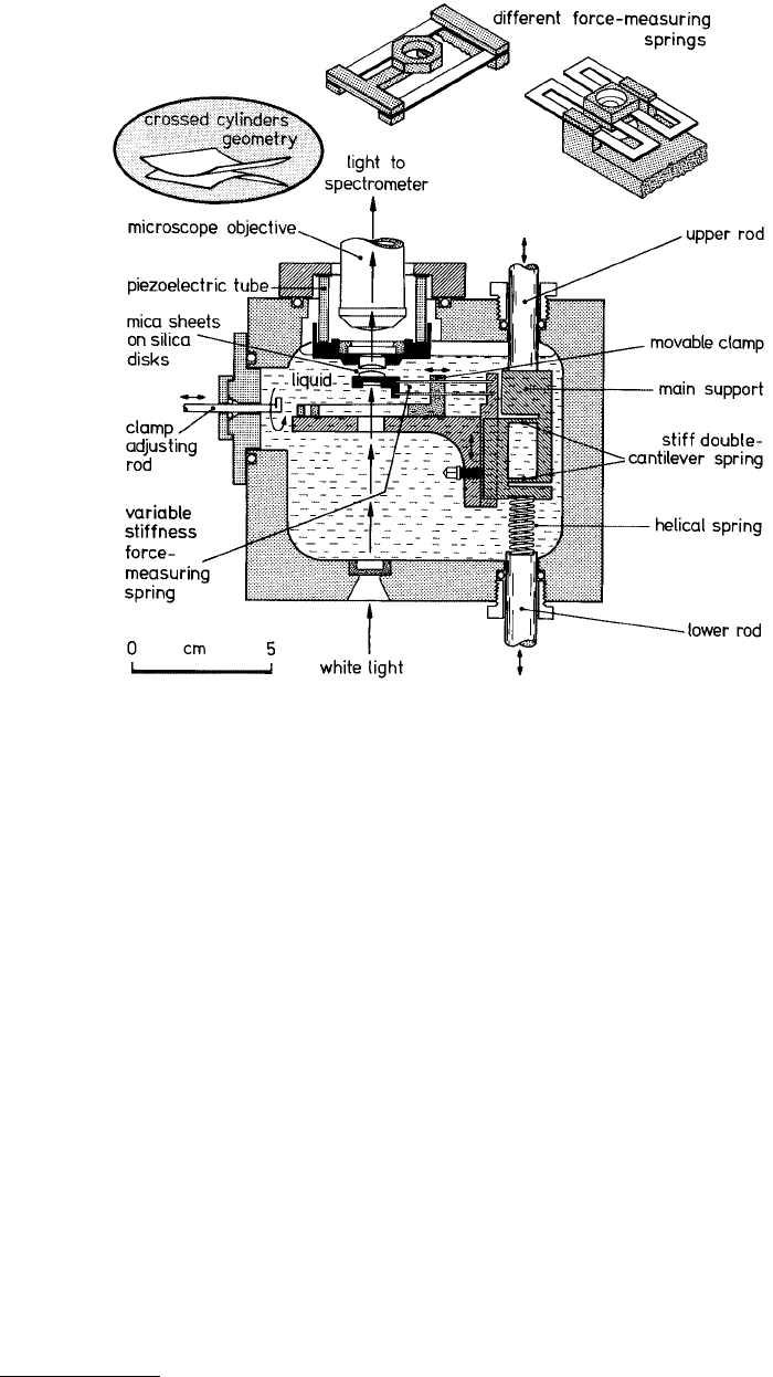
The classical apparatus developed for measuring equilibrium or static intersurface forces in liquids and
vapors by Israelachvili and Adams (1978) consists of a small, airtight stainless steel chamber in which
two molecularly smooth curved mica surfaces can be translated toward or away from each other, see
Figure 1.43. The distance between the two surfaces can also be independently controlled to within
FIGURE 1.42 Gray scale plot of friction profile of a 1 × 1 nm area of a freshly cleaved HOP graphite showing the
atomic-scale variation of topography and friction. Data were taken using a square pyramidal Si
3
N
4
tip. Higher points
are shown by lighter color. (From Ruan, J. and Bhushan, B. (1994), J. Appl. Phys., 76, 5022–5035. With permission.)
For atomic-scale variations in topography, see Figure 1.20a.
© 1999 by CRC Press LLC
±0.1 nm and the force sensitivity is about 10 nN. The technique utilizes two molecularly smooth mica
sheets, each about 2 µm thick, coated with a semireflecting 50- to 60-nm layer of pure silver, glued to
rigid cylindrical silica disks of radius about 10 mm (silvered side down) mounted facing each other with
their axes mutually at right angles (crossed-cylinder position), which is geometrically equivalent to a
sphere contacting a flat surface. The adhesive glue which is used to affix the mica to the support is
sufficiently compliant, so the mica will flatten under the action of adhesive forces or applied load to
produce a contact zone in which the surfaces are locally parallel and planar. Outside of this contact zone
the separation between surfaces increases and the liquid, which is effectively in a bulk state, makes a
negligible contribution to the overall response. The lower surface is supported on a cantilever spring
which is used to push the two surfaces together with a known load. When the surfaces are forced into
contact, they flatten elastically so that the contact zone is circular for the duration of the static or sliding
interactions. The surface separation is measured using optical interference fringes of equal chromatic
order (FECO) which enables the area of molecular contact and the surface separation to be measured to
within 0.1 nm. For measurements, white light is passed vertically up through the two mica surfaces and
the emerging beam is then focused onto the slit of a grating spectrometer. From the positions and shapes
of the colored FECO fringes in the spectrogram, the distance between the two surfaces and the exact
shape of the two surfaces can be measured (as illustrated in Figure 1.44), as can the refractive index of
the liquid (or material) between them. In particular, this allows for reasonably accurate determinations
of the quantity of material deposited or adsorbed on the surfaces and the area of contact between two
molecularly smooth surfaces. Any changes may be readily observed in both static and sliding conditions
FIGURE 1.43 Schematic of the SFA that employs the cross-cylinder geometry. (From Israelachvili, J.N. and Adams,
G.E. (1978), Chem. Soc. J. Faraday Trans. I, 74, 975–1001; and Israelachvili, J.N. (1989), Chemtracts Anal. Phys. Chem.,
1, 1–12. With permission.)
© 1999 by CRC Press LLC
in real time (applicable to the design shown in Figure 1.44) by monitoring the changing shapes of these
fringes.
The distance between the two surfaces is controlled by use of a three-stage mechanism of increasing
sensitivity: coarse control (upper rod) allows positioning of within about 1 µm, the medium control
(lower rod, which depresses the helical spring and which in turn bends the much stiffer double-cantilever
spring by 1/1000 of this amount) allows positioning to about 1 nm, and the piezoelectric crystal tube —
which expands or controls vertically by about 0.6 nm/V applied axially across the cylindrical wall — is
used for final positioning to 0.1 nm.
The normal force is measured by expanding or contracting the piezoelectric crystal by a known amount
and then measuring optically how much the two surfaces have actually moved; any difference in the two
values when multiplied by the stiffness of the force-measuring spring gives the force difference between
the initial and final positions. In this way both repulsive and attractive forces can be measured with a
sensitivity of about 10 nN. The force-measuring springs can be either single-cantilever or double-
cantilever fixed-stiffness springs (as shown in Figure 1.43), or the spring stiffness can be varied during
an experiment (by up to a factor of 1000) by shifting the position of the dovetailed clamp using the
adjusting rod. Other spring attachments, two of which are shown at the top of the figure, can replace
the variable stiffness spring attachment (top right: nontilting, nonshearing spring of fixed stiffness). Each
of these springs are interchangeable and can be attached to the main support, allowing for greater
versatility in measuring strong or weak and attractive or repulsive forces. Once the force F as a function
of distance D is known for the two surfaces of radius R, the force between any other curved surfaces
simply scales by R. Furthermore, the adhesion energy (or surface or interfacial free energy) E per unit
area between two flat surfaces is simply related to F by the so-called Derjaguin approximation (Israelach-
vili, 1991) E = F/2πR. We note that SFA is one of the few techniques available for directly measuring
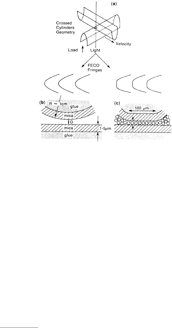
FIGURE 1.44 (a) Cross-cylinder configuration of mica sheet, showing formation of contact area. Schematic of the
fringes of equal chromatic order (FECO) observed when two mica surfaces are (b) separated by distance D and (c)
are flattened with a monolayer of liquid between them. (From Homola, A. M. et al. (1990), Wear, 136, 65–83. With
permission.)
© 1999 by CRC Press LLC
equilibrium force laws (i.e., force vs. distance at constant chemical potential of the surrounding solvent
medium) (Israelachvili, 1989). The SFA allows for both weak or strong and attractive or repulsive forces.
Mostly the molecularly smooth surface of mica is used in these measurements (Pashley, 1981); however,
silica (Horn et al., 1989) and sapphire (Horn and Israelachvili, 1988) have also been used. It is also
possible to deposit or coat each mica surface with metal films (Christenson, 1988; Smith et al., 1988),
carbon and metal oxides (Hirz et al., 1992), adsorbed polymer layers (Patel and Tirrell, 1989), and
surfactant monolayers and bilayers (Christenson, 1988; Israelachvili, 1987, 1991; Israelachvili and
McGuiggan, 1988). The range of liquids and vapors that can be used is almost endless.
1.3.4.1.2 Sliding Attachments for Tribological Studies
Thus far we have described a measurement technique which allows measurements of the normal forces
between surfaces, that is, those occurring when two surfaces approach or separate from each other.
However, in tribological situations, it is the transverse or shear forces that are of primary interest when
two surfaces slide past each other. There are essentially two approaches used in studying the shear response
of confined liquid films. In the first approach (constant-velocity friction or steady-shear attachment),
the friction is measured when one of the surfaces is traversed at a constant speed over a distance of several
hundreds of microns (Israelachvili et al., 1988; Homola, 1989; Gee et al., 1990; Homola et al., 1990, 1991;
Klein et al., 1991; Hirz et al., 1992). The second approach (oscillatory-shear attachment) relies on the
measurement of viscous dissipation and elasticity of confined liquids by using periodic sinusoidal oscil-
lations over a range of amplitudes and frequencies (Van Alsten and Granick, 1988, 1990a,b; Peachey
et al., 1991; Hu et al., 1991; Luengo et al., 1997).
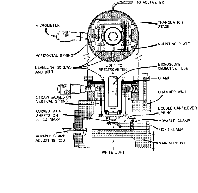
For the constant-velocity friction (steady-shear) experiments, the SFA was outfitted with a lateral sliding
mechanism (Israelachvili et al., 1988; Israelachvili, 1989; Homola, 1989; Gee et al., 1990; Homola et al.,
1990, 1991) allowing measurements of both normal and shearing forces (Figure 1.45). The piezoelectric
FIGURE 1.45 Schematic of shear force apparatus. Lateral motion is initiated by a variable-speed motor-driven
micrometer screw that presses against the translation stage which is connected through two horizontal double-
cantilever strip springs to the rigid mounting plate. (From Israelachvili, J.N. et al. (1988), Science, 240, 189–190; and
Israelachvili, J.N. (1989), Chemtracts Anal. Phys. Chem., 1, 1–12. With permission.)