Barber J.R. Intermediate Mechanics of Materials
Подождите немного. Документ загружается.


Problems 485
10.21*. An infinite solid consists of an incompressible elastic-plastic material which
has modulus of rigidity G, and which yields at a shear stress
τ
Y
. The solid contains
a long cylindrical hole of radius b which contains fluid at pressure p. Find the radial
and circumferential stresses in the solid for the case where p is sufficient for yielding
to have progressed to a radius c.
Find the radial displacement at r = c and hence show that
p
τ
Y
= 1 + ln
G
τ
Y
∆
V
V
,
where V is the original volume of the hole and
∆
V is the change in its volume due to
the pressure p.
10.22. A thin steel annular disk of internal radius 2 in and external radius 8 in is
subjected to internal pressure at the inner radius, the outer edge being traction-free.
Obtain expressions for the stresses in the disk when the pressure p is sufficiently large
for there to be a plastic zone of outer radius c. The appropriate material properties
are E =30×10
6
psi,
ν
=0.3,S
Y
= 100×10
3
psi.
Show that the maximum value of p that can be applied is p = S
Y
and that in this
condition, part of the disk remains in the elastic state. Describe the resulting failure
in physical terms.
10.23. A pressure vessel in the form of a long circular cylinder with closed ends is
subjected to an external pressure p. The internal radius of the cylinder is a and the
external radius is 2a. Show that if yielding is governed by the Tresca criterion and if
the value of p is large enough, yielding occurs up to a radius c given by
S
Y
ln
c
a
− p +
1
2
S
Y
1 −
c
2
4a
2
= 0 ,
where S
Y
is the tensile yield stress of the material.
Sketch the distribution of radial and circumferential stress through the cylinder
wall for the case where c = 1.2a.
10.24. A rigid cylindrical container of radius a is sealed when it is just full of water
of density
ρ
at pressure p
0
. It is then rotated about its axis at speed
Ω
. Treating water
as an elastic-plastic material which yields at zero shear stress, but which has a bulk
modulus K, find the pressure distribution in the water. Neglect gravitational effects.
At what speed would you expect your solution to cease to be valid?
Note: The bulk modulus is defined such that
e ≡e
rr
+ e
θθ
+ e
zz
= −
p
K
where p is the hydrostatic pressure.

486 10 Thick-walled Cylinders and Disks
10.25. A long solid cylinder of radius a is rapidly heated around its curved surface
producing an instantaneous temperature distribution
T = T
0
+ T
1
r
2
a
2
If T
1
is large enough for some yielding to occur, find the radius of the elastic region
and the instantaneous stress distribution in the cylinder. Assume that the material
obeys Tresca’s yield criterion and that the tensile yield stress S
Y
is independent of
temperature.
10.26. A long circular cylinder of inside radius a and outside radius na has closed
ends. The material may be assumed to be elastic-perfectly plastic, obeying Tresca’s
yield criterion, with a yield stress S
Y
in uniaxial tension. An external pressure just
sufficient to cause yielding throughout the cylinder is applied and then removed. Find
the distribution of residual stress and hence the maximum value of n if there is to be
no yielding on unloading.
10.27. A cylindrical pressure vessel of inside radius a, outside radius 2a and closed
ends is subjected to an internal pressure p. Show that yield will occur throughout the
vessel if p =S
Y
ln2.
If this pressure is applied and then released, show that the residual circumferen-
tial stress at the inner radius is
−
8ln2
3
−1
S
Y
.
11
Curved Beams
The classical theory of the bending of beams is strictly exact if the axis of the beam
is straight, the loads are applied only at the ends and the cross section is uniform
along the length, which is much larger than any other linear dimension. However,
the resulting equations are so simple that engineers routinely apply them outside
this restrictive context and this usage is appropriate as long as we recognize that the
resulting approximation may underestimate the bending stresses.
A particular case in which this occurs is that where the axis of the beam is curved.
Important practical applications include chain links, crane hooks, pipe bends and
curved segments of machine tool frames.
11.1 The governing equation
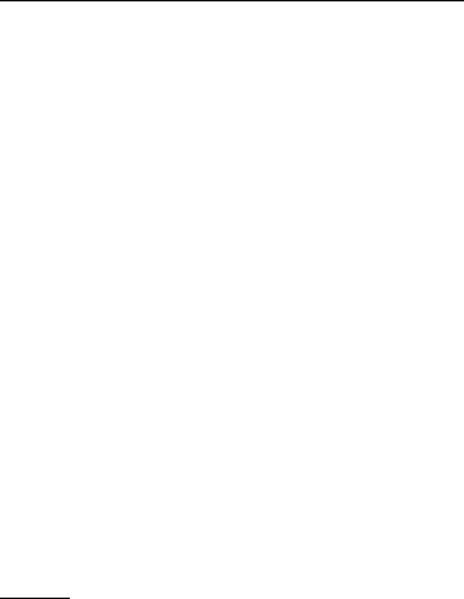
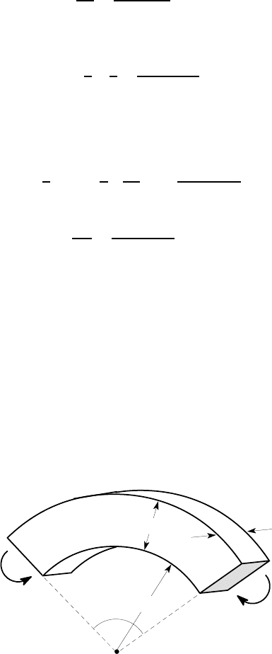
Figure 11.1 (a) shows a segment of a curved beam subtending a small angle
δθ
at its centre of curvature O and transmitting a bending moment M. The resulting
deformation is illustrated in Figure 11.1 (b), where the reference frame has been
chosen so as to leave the left end of the segment fixed.
As in the elementary analysis of straight beams, a convenient starting point is the
assumption
1
that plane transverse sections remain plane during the deformation. The
right end of the segment will rotate through some angle
δφ
. This in turn causes the
subtended angle in the deformed segment to increase to
δθ
+
δφ
and the centre of
curvature to move to O
′
as shown.
1
As in §5.1, we can establish a more rigorous starting point by remarking that transverse
plane sections must all deform to the same shape, but will in general suffer different rigid
body translation and rotation. However, if the material is isotropic, it follows from symme-
try that plane sections remain plane.
J.R. Barber, Intermediate Mechanics of Materials, Solid Mechanics and Its Applications 175,
2nd ed., DOI 10.1007/978-94-007-0295-0_11, © Springer Science+Business Media B.V. 2011
488 11 Curved Beams
M
M
δθ
O
r
δθ
O
r
O
δθ+δφ
δφ
s
(a) (b)
Figure 11.1: (a) Curved beam loaded by a bending moment M; (b) the resulting
deformation
We denote the radius of a given point as r in the undeformed state and s in the
deformed state. The circumferential strain can therefore be written
e
θθ
=
s(
δθ
+
δφ
) −r
δθ
r
δθ
→
s
r
1 +
d
φ
d
θ
−1 (11.1)
in the limit where
δθ
→ 0.
We anticipate the existence of a neutral surface at some radius r = ˆr at which
the circumferential strain is zero. The corresponding radius ˆs after deformation is
therefore (by definition) given by
ˆs
1 +
d
φ
d
θ
= ˆr . (11.2)
From the geometry of Figure 11.1 (b), the distance OO
′
is
d = r −s = ˆr − ˆs
and hence
s = r −d = r − ˆr + ˆs . (11.3)
The strain (11.1) can therefore be written
e
θθ
=
1 −
ˆr
r
+
ˆs
r
1 +
d
φ
d
θ
−1 =
1 −
ˆr
r
d
φ
d
θ
, (11.4)
11.1 The governing equation 489
using (11.2).
If the stress components
σ
rr
,
σ
zz
can be assumed to be negligible, we then have
σ
θθ
= Ee
θθ
= E
1 −
ˆr
r
d
φ
d
θ
. (11.5)
This stress acts on the cross section of the beam in the circumferential direction, as
shown in Figure 11.2 and it follows that the total circumferential force is
F =
ZZ
A
σ
θθ
dA = E
d
φ
d
θ
ZZ
A
1 −
ˆr
r
dA , (11.6)
where the integral is performed over the cross-sectional area A of the beam.
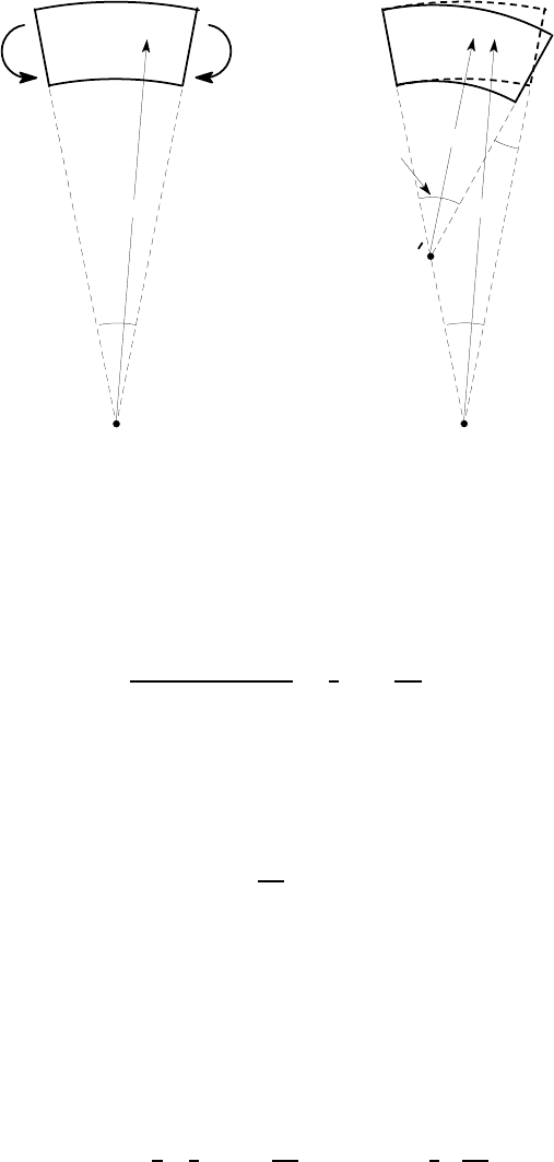
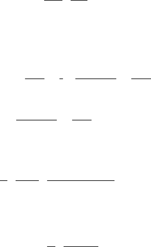
O
r
σ
θθ
Figure 11.2: The circumferential stress,
σ
θθ
As with straight beams, it is convenient to treat circumferential (axial) load-
ing and bending separately and then superpose the resulting stress distributions. We
therefore focus initially on the case where the circumferential force is zero, in which
case
ZZ
A
1 −
ˆr
r
dA = 0
and hence
A = ˆr
ZZ
A
dA
r
, (11.7)
which serves to determine the radius ˆr defining the location of the neutral surface.
11.1.1 Rectangular and circular cross sections
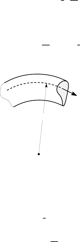
Figure 11.3 (a) shows a curved beam of rectangular cross section, with inner radius
a, outer radius b and thickness t.
490 11 Curved Beams
O
t
b
a
L
c
b
a
L
c
dr
t
r
(a) (b)
Figure 11.3: Curved beam of rectangular cross section
The integral in equation (11.7) for this cross section can be evaluated using the
rectangular elemental area dA =tdr shown shaded in Figure 11.3 (b).
We then have
ZZ
A
dA
r
=
Z
b
a
tdr
r
= t ln(b/a) . (11.8)
The cross-sectional area is
A = (b −a)t
and hence the neutral radius ˆr is given by
ˆr =
(b −a)t
t ln(b/a)
=
(b −a)
ln(b/a)
. (11.9)
If the beam is only slightly curved, so that a,b≫(b−a) and b/a is close to unity,
it can be shown that ˆr →(a+b)/2. In other words, the neutral surface approaches the
mid-plane of the section as in the elementary theory.
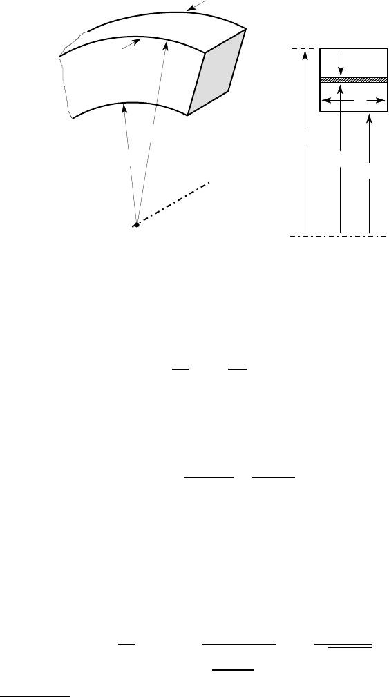
Figure 11.4 (a) shows a curved beam of circular cross section of radius a, whose
axis defines an arc of radius R. To evaluate the integral in equation (11.7), we use the
shaded elemental area of Figure 11.4 (b), obtaining
2
ZZ
A
dA
r
=
Z
a
0
Z
2
π
0
ρ
d
θ
d
ρ
(R +
ρ
cos
θ
)
=
Z
a
0
2
πρ
d
ρ
p
R
2
−
ρ
2
= 2
π
(R −
p
R
2
−a
2
) . (11.10)
2
see for example I.S. Gradshteyn and I.M. Ryzhik (1980), Tables of Integrals, Series and
Products, Academic Press, New York, 3.613.
11.1 The governing equation 491
O
L
c
a
R
L
c
a
R
ρδρδθ
θ
ρ
(a) (b)
Figure 11.4: Curved beam of circular cross section
The cross-sectional area of the circle is
π
a
2
and the neutral radius is therefore
ˆr =
π
a
2
2
π
(R −
√
R
2
−a
2
)
=
a
2
2(R −
√
R
2
−a
2
)
, (11.11)
from (11.7).
11.1.2 The bending moment
Referring back to Figures 11.1, 11.2, we can develop an expression for the bending
moment M by taking moments about the curvature axis O. We obtain
M =
ZZ
A
σ
θθ
rdA = E
d
φ
d
θ
ZZ
A
1 −
ˆr
r
rdA
= E
d
φ
d
θ
ZZ
A
rdA −
ZZ
A
ˆrdA
,
using (11.5).
The first integral is equal to A¯r, where ¯r is the distance from O to the centroid of
A, so the moment expression can be written in the condensed form
M = EA(¯r − ˆr)
d
φ
d
θ
. (11.12)
The stress due to the bending moment M can then be obtained by eliminating
d
φ
/d
θ
between equations (11.5, 11.12), with the result
σ
θθ
=
M
A(¯r − ˆr)
1 −
ˆr
r
. (11.13)
492 11 Curved Beams
The deformation caused by the moment can be characterized by the derivative
d
φ
d
θ
=
M
EA(¯r − ˆr)
. (11.14)
Alternatively, we note that the change of curvature,
∆κ
of the neutral surface is
defined by
∆κ
≡
1
ˆs
−
1
ˆr
=
M
EAˆr(¯r − ˆr)
, (11.15)
from equations (11.2, 11.14).
As in Chapter 3 (§3.2), we can compute the strain energy stored in the beam
segment
δθ
by equating it to the work done by the moment M during its application.
We obtain
δ
U =
1
2
M
δφ
=
1
2
M
d
φ
d
θ
δθ
=
M
2
δθ
2EA(¯r − ˆr)
,
from (11.14) and hence
dU
d
θ
=
M
2
2EA(¯r − ˆr)
. (11.16)
This result permits us to use the energy methods of Chapter 3 in curved beam prob-
lems (see for example Problems 11.10, 11.11).
Equations (11.12–11.16) contain the factor (¯r−ˆr), which is often small in com-
parison with ¯r. It is important to take a sufficient number of significant digits in the
calculation of these quantities to ensure that accuracy is not lost. This will be clarified
by the following example.
Example 11.1
A curved beam of 1 in square cross section and inner radius 2 in subtends an angle
of 90
o
at the centre, as shown in Figure 11.5. Find the stresses at the inner and outer
radii when the beam is subjected to a bending moment of 100 lb ft. Find also the
relative rotation of the ends of the beam, if the material is steel with E =30×10
6
psi.
O
100 lb ft
100 lb ft
1
2
1
90
o
all dimensions in inches
Figure 11.5
11.1 The governing equation 493
The inner and outer radii are a=2 in, b =3 in, respectively, so the neutral radius
can be found from equation (11.9) as
ˆr =
(b −a)
ln(b/a)
=
1
ln(1.5)
= 2.46630 in.
The centroidal radius is
¯r = 2.5 in.
Notice that we have to take a larger number of significant digits in ˆr, ¯r than usual
because the stress and deformation expressions involve the difference (¯r−ˆr) between
quantities of comparable magnitude.
The stress at the outer radius (b = 3 in) can now be found from equation (11.13)
as
σ
θθ
(b) =
M
A(¯r − ˆr)
1 −
ˆr
b
=
100 ×12
1(2.5 −2.46630)
1 −
2.46630
3
= 6335 psi (tensile).
A similar calculation for the inner radius, a=2 in, yields
σ
θθ
(a) =
100 ×12
1(2.5 −2.46630)
1 −
2.46630
2
= −8302 psi (compressive).
Notice that the magnitude of the stress at the inner radius exceeds that at the outer
radius. This is due to the stress concentrating effect of the curvature and is more
pronounced when the ratio a/b is smaller.
The deformation of the beam is defined by equation (11.14), from which we
obtain
d
φ
d
θ
=
M
EA(¯r − ˆr)
=
100 ×12
30 ×10
6
×1(2.5 −2.46630)
= 1.187 ×10
−3
.
The relative rotation of the ends is therefore
δφ
= 1.187 ×10
−3
×90
o
= 0.107
o
.
It is instructive to compare the maximum stresses with the predictions of the
elementary bending theory for straight beams, which gives
σ
max
=
Mc
I
=
100 ×12 ×0.5
1
4
/12
= 7200 psi.
The elementary theory predicts equal and opposite stresses at the inner and outer
radii, so it underestimates the stress at the inner radius and overestimates it at the
outer radius, in each case by about 14%.
494 11 Curved Beams
11.1.3 Composite cross sections
The preceding analysis applies to any cross section which is symmetric about a plane
normal to the curvature axis of the beam. For a general cross section, we must first de-
termine the neutral radius ˆr from equation (11.7) and the centroidal radius ¯r using the
methods of §4.3. The circumferential stress distribution and the moment-curvature
relation are then given by equations (11.13–11.15).
For composite areas
A = A
1
+ A
2
+ A
3
+ ... ,
the integral in (11.7) can be written as the sum of a series of separate integrals, as in
§4.3. We obtain
A
ˆr
=
ZZ
A
dA
r
=
ZZ
A
1
dA
r
+
ZZ
A
2
dA
r
+
ZZ
A
3
dA
r
+ ... (11.17)
The results of §11.1.1 therefore permit us to write down the integral for any area
made up of rectangular and/or circular segments.
11.1.4 Axial loading
The analysis so far has been restricted to the case of pure bending, where the axial
force F defined by equation (11.6) is zero. In this section, we shall consider the
opposite case, where there is an axial force, but no bending moment.
Figure 11.6 (a) shows a segment of curved beam loaded by an axial force F
on its ends. The segment is clearly not in equilibrium, since the two forces are not
co-linear, so we conclude that a curved beam cannot support a uniform axial load
along its length without additional loading. The simplest loading scenario leading
to a uniform axial force is that shown in Figure 11.6 (b), where the forces F are
balanced by a uniformly distributed radial load of w per unit length. If the subtended
angle
δθ
is sufficiently small, the equilibrium equation for this figure is
wR
δθ
−2F
δθ
2
= 0
and hence
w =
F
R
.
This loading leads to an axisymmetric state of stress and deformation and is
in fact analogous to that in the membrane theory of axisymmetric shells (Chapter
8). The subtended angle
δθ
must remain the same after deformation and hence the
circumferential strain is
e
θθ
=
u
r
r
,
where u
r
is the radial displacement.
3
3
cf equation (8.3).