Barber J.R. Intermediate Mechanics of Materials
Подождите немного. Документ загружается.

10.4 Composite cylinders, limits and fits 465
be different in the two components and will be denoted by A
1
,B
1
for the inner and
A
2
,B
2
for the outer cylinder. Of course, the material constants may also differ and
will be denoted similarly as E
1
,
ν
1
,
α
1
,E
2
,
ν
2
,
α
2
, respectively.
There are now four unknown constants and we require four equations to deter-
mine them. Two of these equations come from the conditions at the inner and outer
radii, as before. Two additional conditions must be satisfied at the interface r =c.
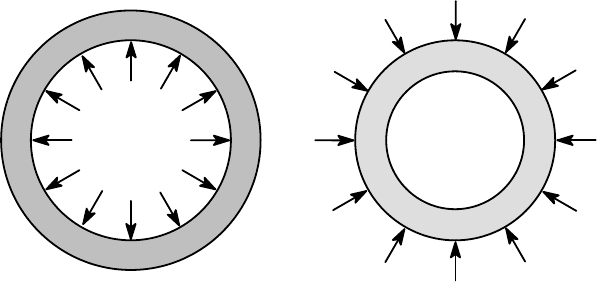
(i) By Newton’s third law, the contact pressure p
c
must act equally on both contact-
ing surfaces, so that
p
c
= −
σ
rr
1
(c) = −
σ
rr
2
(c) (10.32)
(see Figure 10.11).
(ii) The fact that the surfaces are in contact imposes a kinematic constraint on the
displacements at the interface. Suppose the inner radius of the outer cylinder is
c and the outer radius of the inner cylinder is c+
δ
where
δ
≪c. We describe
δ
as the radial interference. If the two cylinders now experience different radial
displacements u
r
1
,u
r
2
, the final radii will be c + u
r
2
(c) and c+
δ
+ u
r
1
(c) and
these must be equal (i.e. the two surfaces must be at the same place), if the
cylinders are to be in contact. Thus
c + u
r
2
(c) = c +
δ
+ u
r
1
(c) (10.33)
or
u
r
2
(c) −u
r
1
(c) =
δ
. (10.34)
p
c
p
c
Figure 10.11: Free-body diagram for the composite cylinder
Usually the conditions at the inner and outer surfaces of the composite cylinder
and the radial interference
δ
will be known and we shall wish to determine the in-
terface pressure p
c
and the stress field in the cylinders. However, it is considerably
easier to solve problems in which p
c
is prescribed instead of
δ
, since then the prob-
lems for the two cylinders are uncoupled and can be solved separately. We can take
advantage of this by pretending that p
c
is prescribed in all problems (writing it as a
symbol in the resulting equations) and then eliminating or solving for it at the end.
We shall illustrate this procedure with the following example.
466 10 Thick-walled Cylinders and Disks
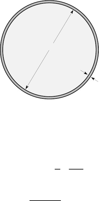
Example 10.3 — Wheel and tyre assembly
A wheel consisting of a solid steel disk of diameter 10 in. carries a hardened steel
tyre of thickness 0.15 in., as shown in Figure 10.12. The radial interference at the
interface before assembly is 0.012 in. and assembly is to be achieved by heating the
tyre until it can be slipped over the wheel with a radial clearance of 0.005 in.
Find the temperature to which the tyre must be heated, and the maximum tensile
stress in the tyre after the assembly has cooled down. Assume that E =30×10
6
psi,
ν
=0.3,
α
=7×10
−6
per
o
F for both components.
0.15
10
all dimensions in inches
Figure 10.12: Wheel with a hardened steel tyre
To find the temperature required for assembly, we note that the tire must ex-
pand sufficiently to convert a radial interference of 0.012 in. to a radial clearance
of 0.005 in. Thus, the radial displacement u
r
due to thermal expansion must be
0.012+0.005 = 0.017 in. Now
e
θθ
=
α∆
T =
u
r
r
=
0.017
5
and hence the required temperature difference is
∆
T =
0.017
7 ×10
−6
×5
= 486
o
F .
Notice that the radius of the wheel is 5 in. (Take care not to confuse diameter with
radius or radial interference with diametral interference.)
To find the stress state after assembly, we denote the final interface pressure by
p
c
. It then follows from equation (10.21) that A
1
= −p
c
, since there are no thermal
or rotational effects, and B
1
must be zero to preserve continuity at r = 0. Thus, the
radial displacement at the surface of the disk is
10.4 Composite cylinders, limits and fits 467
u
r
1
=
A
1
(1 −
ν
1
)r
E
1
= −
0.7 ×5 × p
c
30 ×10
6
= −0.1167 ×10
−6
p
c
,
from equation (10.23).
For the tyre, we have
σ
rr
=−p
c
at r =5 in and
σ
rr
=0 at r=5.15 in and hence
A
2
+
B
2
5
2
= −p
c
; A
2
+
B
2
5.15
2
= 0 ,
with solution
A
2
= 16.42p
c
; B
2
= −435.5p
c
.
Substituting into (10.23), we find that the radial displacement at the inner radius of
the tyre (r =5) is
u
r
2
=
A
2
(1 −
ν
2
)r
E
2
−
(1 +
ν
2
)B
2
E
2
r
=
A
2
×0.7 ×5
30 ×10
6
−
B
2
×1.3
30 ×10
6
×5
= 5.69 ×10
−6
p
c
.
Finally, we substitute the above expressions for u
r1
,u
r2
into (10.34), obtaining
5.69 ×10
−6
p
c
+ 0.1167 ×10
−6
p
c
= 0.012
and hence p
c
=2066 psi.
The maximum tensile stress in the tyre occurs at the inner radius and is
σ
θθ
= A
2
−
B
2
5
2
= 33.84p
c
= 70 ksi .
Discussion
This example illustrates a calculation procedure which can be adapted to most prob-
lems involving composite cylinders. However, in the spirit of §1.2.2, we note that an
acceptable result can often be obtained by a considerably shorter calculation. A clue
to this is provided by the fact that the two radial displacements are very different
in magnitude (5.69 ≫0.1167), so that the smaller of them can be neglected without
affecting the result. In physical terms, this is equivalent to saying that the central disk
is so much stiffer than the tyre that u
r
1
can be neglected and the problem treated as
one of assembling a tyre over a rigid disk. Furthermore, the tyre is thin relative to
its radius (i.e. 0.15≪5) and hence a thin-walled cylinder solution can be used for it,
which amounts to assuming that
σ
θθ
≫
σ
rr
and is uniform across the thickness (see
Chapter 8).
With these idealizations, we obtain
u
r
2
≈
δ
= 0.012 in.
e
θθ
=
u
r
2
r
≈
0.012
5
= 0.0024
σ
θθ
= Ee
θθ
≈30 ×10
6
×0.0024 = 72 ksi ,

468 10 Thick-walled Cylinders and Disks
which is within 3% of the more exact result. An even better approximation can be
obtained by using the average tyre radius, 5.075 inches, in calculating e
θθ
, giving a
stress of 71 ksi.
Of course, this problem involves a fairly thin outer cylinder and the thin-walled
approximation can be expected to be less accurate when the thickness is greater. This
question is further explored in Problem 10.12.
10.4.2 Limits and fits
Example 10.3 shows that a fairly small difference between the inside diameter of
the tyre and the outside diameter of the wheel leads to quite substantial stresses in
the tyre. In practice, these dimensions can only be guaranteed in a manufacturing
operation within some finite limits or tolerances and the components made to the
design will show some statistical scatter. It is therefore important to specify the ac-
ceptable tolerances on the two mating dimensions and to choose these so that they
are achievable by a practicable manufacturing operation.
Shrink or force fits are widely used to assemble gears and other components
onto cylindrical shafts, so sets of standards have been established defining appro-
priate amounts of interference
δ
and tolerance limits on the dimensions for various
categories of fits.
8
If gears and shafts are randomly assembled, situations may arise where the largest
permissible shaft is assembled to the smallest permissible hole and this might result
in too large a tensile hoop stress at the inner radius of the gear. The opposite case of
a small shaft assembled to a large hole will give a loose fit which might not develop
sufficient contact pressure to maintain integrity under load. This problem can be
alleviated to some extent, at the cost of additional organizational costs, by sorting
the manufactured components into size ranges and assembling predominantly large
shafts to large holes etc.
10.5 Pl astic deformation of dis ks and cylinders
The general procedure outlined in §10.1 can be used for disks and cylinders of in-
elastic materials if the appropriate inelastic constitutive relations are used in place of
equations (10.8–10.10). In this section, we shall consider the special case of a ma-
terial that behaves elastically up to the yield stress and thereafter yields at constant
stress (i.e. without work hardening). This idealization of ductile material behavior
was used in Chapter 5 in the analysis of elastic-plastic bending and its justification is
discussed in §5.2.3. The corresponding uniaxial tensile stress-strain relation for both
loading and unloading is shown in Figure 5.4.
If a disk or cylinder of an elastic-plastic material is subjected to monotonically
increasing load, the stresses will initially be given by the preceding elastic analysis
8
See for example, American Standard Limits for Cylindrical Parts ANSI B4.2-1978, Amer-
ican Society of Mechanical Engineers, New York, or ISO 17.040.10 Limits and Fits at
http://www.iso.org

10.5 Plastic deformation of disks and cylinders 469
until a load is reached at which yielding commences, usually at the inner or outer
radius. Further increase of load will cause a plastic zone to grow, starting from the
point of first yield. Eventually, the plastic zone will extend over the entire body and
this fully-plastic state defines the maximum load the body can sustain without to-
tal collapse. As in the analysis of elastic-plastic bending, the limiting cases of first
yield and full plasticity are considerably simpler than the intermediate condition that
involves both elastic and plastic zones.
In cylinders and disks, at least two of the three principal stresses
σ
rr
,
σ
θθ
,
σ
zz
are
non-zero and hence we need to supplement the uniaxial stress-strain relation with
information about the influence of the other stress components on the conditions at
yield. The general question of yield criteria is discussed in §2.2.3. For the present
analysis, we shall adopt Tresca’s yield criterion,
9
which states that the maximum
shear stress
τ
max
during yielding is equal to a critical value
τ
Y
. More specifically, we
assume that the material behaves elastically as long as
τ
max
<
τ
Y
and thereafter yields
with
τ
max
=
τ
Y
.
In Chapter 2, we showed that the maximum shear stress is
τ
max
= max
|
σ
1
−
σ
2
|
2
,
|
σ
2
−
σ
3
|
2
,
|
σ
3
−
σ
1
|
2
,
where
σ
1
,
σ
2
,
σ
3
are the three principal stresses. If yielding occurs in uniaxial tension
at a stress S
Y
, we conclude that
τ
Y
=S
Y
/2. For the present axisymmetric problem, the
principal stresses are
σ
rr
,
σ
θθ
,
σ
zz
and hence Tresca’s yield criterion can be expressed
in the form
max(|
σ
rr
−
σ
θθ
|,|
σ
θθ
−
σ
zz
|,|
σ
zz
−
σ
rr
|) = S
Y
. (10.35)
If we knew which of the three stress differences was the greatest, this equation
and the equation of motion (10.3) would constitute two equations for the two un-
known stress components
σ
rr
,
σ
θθ
in any region that is yielding. Recall that the third
stress component
σ
zz
is zero under plane stress conditions and can be determined by
axial equilibrium arguments for plane strain.
One approach is to use trial and error. We tentatively assume that a given stress
difference is the greatest and solve the plasticity problem under this assumption. We
can then check the final stress distribution to see whether our initial assumption is
confirmed. In the worst case, we could try all possible combinations until a consistent
solution is obtained, but a better approach is to start with the solution of the corre-
sponding elastic solution and determine the stress difference governing first yield. In
most cases, this will also govern the deformation in the plastic zone in the subsequent
elastic-plastic problem. The elastic solution also tells us the location at which yield
first occurs and hence shows where the plastic zone will develop at loads above that
for first yield.
9
The advantage of using Tresca’s rather than von Mises’ yield criterion is that the former
leads to linear differential equations that can be solved analytically.
470 10 Thick-walled Cylinders and Disks
10.5.1 First yield
For first yield, the deformation is everywhere elastic and the solution proceeds ex-
actly as in the preceding sections, except that the load is unknown and must be ex-
pressed symbolically. We then take the further step of identifying the maximum stress
difference and equating it to S
Y
, to determine the load and the location at which yield
first occurs. This is best illustrated by example. Consider the thick cylinder loaded
by internal pressure, for which the stress field is illustrated in Figure 10.9 above. We
note that the greatest stress difference (i.e. the greatest distance between any two of
the three lines) occurs at the inner radius r =a and is the difference between
σ
θθ
and
σ
rr
. It follows that yield will start at the inner radius when
σ
θθ
−
σ
rr
= S
Y
. (10.36)
Substituting for the stresses from equations (10.30) and setting r = a for the inner
radius, we find that this occurs at a pressure p
Y
given by
a
2
p
Y
(b
2
−a
2
)
1 +
b
2
a
2
−
a
2
p
Y
(b
2
−a
2
)
1 −
b
2
a
2
= S
Y
.
The internal pressure for first yield is therefore
p
Y
=
S
Y
2
1 −
a
2
b
2
. (10.37)
10.5.2 The fully-plastic solution
If the internal pressure is increased beyond p
Y
, we expect yield to occur at the inner
radius and further increase in pressure will cause the region of plastic deformation to
extend outwards. Eventually, the whole cylinder will be plastically deformed and no
further increase in pressure can occur without collapse. We shall denote the pressure
at which this occurs (the fully plastic pressure) by p
P
.
To solve the fully plastic problem, we tentatively assume that plasticity is gov-
erned by the same criterion [equation (10.36)] as at first yield. We can then eliminate
σ
θθ
between equations (10.4, 10.36) to obtain
d
σ
rr
dr
−
S
Y
r
= 0 ,
which has the general solution
σ
rr
= S
Y
ln(r) +C , (10.38)
where C is an arbitrary constant of integration.
At the fully-plastic state, the internal pressure is p
P
and the external pressure is
zero, giving the two boundary conditions
10.5 Plastic deformation of disks and cylinders 471
σ
rr
(a) = S
Y
ln(a) +C = −p
P
σ
rr
(b) = S
Y
ln(b) +C = 0 .
Solving these equations for C, p
P
, we find
C = −S
Y
ln(b) ; p
P
= S
Y
ln(b/a)
and substituting for C into (10.38, 10.36), we obtain the complete stress field as
σ
rr
= −S
Y
ln(b/r)
σ
θθ
= S
Y
−S
Y
ln(b/r) .
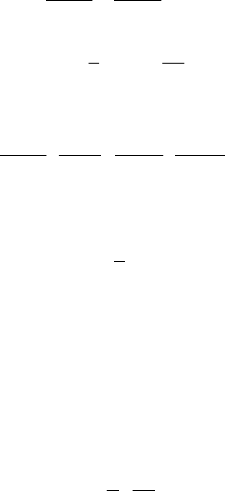
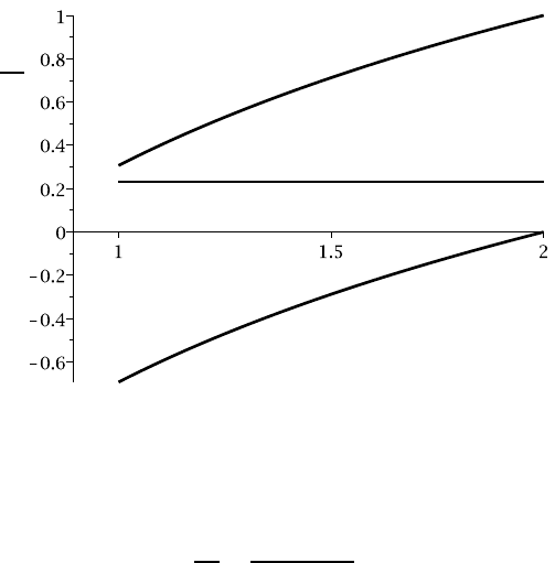
These expressions as well as that for
σ
zz
from (10.31) are shown in Figure 10.13,
for the case where b = 2a. Notice that the curves for
σ
θθ
and
σ
rr
are parallel and
separated by a distance S
Y
, as demanded by the yield condition (10.36). We also
notice that, for the case illustrated, (
σ
θθ
−
σ
rr
) is indeed the greatest stress difference
throughout the cylinder, as we assumed at the beginning. However, if a/b<0.45, the
curves for
σ
θθ
and
σ
zz
cross near r= a and the solution is not valid in this range. We
shall discuss the resolution of this difficulty in §10.5.4 below.
σ
S
Y
σ
θθ
σ
zz
r/a
σ
rr
Figure 10.13: Stress field in the fully-plastic state
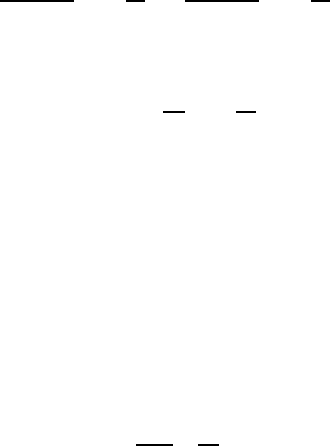
It is instructive to compare the internal pressure, p
P
for full plasticity with that
for first yield, p
Y
. We have
p
P
p
Y
=
2ln(b/a)
(1 −a
2
/b
2
)
.
This ratio is plotted in Figure 10.14. For a thin-walled cylinder, a/b is close to
unity and a comparatively small additional pressure is sufficient to cause complete
collapse once yield starts to occur. The curve is shown dashed for a/b < 0.45, since
the solution loses validity in this range.
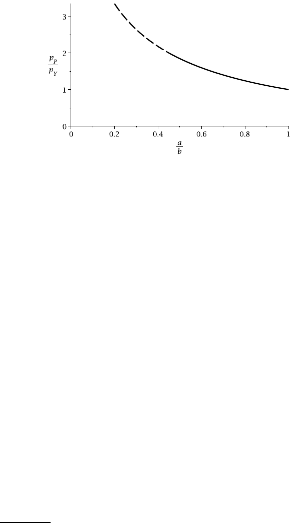
472 10 Thick-walled Cylinders and Disks
Figure 10.14: The ratio p
P
/p
Y
as a function of the radius ratio a/b
10.5.3 Elastic-plastic problems
If the loading is intermediate between the first yield and fully-plastic limits, we can
anticipate a solution in which part of the cylinder or disk is elastic and the rest plastic.
The radius c of the circular boundary between these zones is an additional unknown
to be determined. Additional equations to determine this radius and the arbitrary con-
stants in the solution will come from continuity conditions at the interface between
the elastic and plastic zones. In fact, the procedure is somewhat similar to that used
for composite elastic cylinders in §10.4.
In a typical problem, there are four unknowns comprising:-
• the two constants A,B in the elastic zone — see equations (10.20–10.22) for
plane stress or (10.25–10.27) for plane strain;
• a single constant C in the plastic zone — see for example, equation (10.38); and
• the unknown radius c defining the boundary of the plastic zone.
To determine them, we have the four conditions:-
• specified pressure or displacement at the inner and outer radii r= a, b;
• continuity of radial stress,
σ
rr
at r = c as in equation (10.32);
• continuity of circumferential stress
σ
θθ
at r = c.
This last condition requires some comment, since it does not apply in problems for
composite elastic cylinders and disks. However, here we are dealing with a single
cylinder or disk, part of which has yielded and part of which is still elastic. If the
load is increased slightly, the plastic zone will extend, indicating that the material
just inside the elastic zone must have been on the point of yielding. Since the yield
criterion usually
10
involves the circumferential stress
σ
θθ
, this implies that this stress
component must be continuous across the elastic-plastic boundary.
10
but see §10.5.4.
10.5 Plastic deformation of disks and cylinders 473
Example 10.4
A thin solid disk of outer radius a rotates at speed
Ω
. The outer edge of the disk is
traction-free and thermal effects are negligible. The material of the disk is ductile
with uniaxial yield stress S
Y
, Young’s modulus E, Poisson’s ratio
ν
and density
ρ
.
Find the rotational speed for first yield
Ω
Y
and for complete plastic failure
Ω
P
.
Find also the radius c defining the boundary between the elastic and plastic zones
for
Ω
Y
<
Ω
<
Ω
P
.
First yield
For the elastic solution we have
σ
rr
= −
(3 +
ν
)
ρΩ
2
r
2
8
+ A +
B
r
2
,
from equation (10.21). As long as the whole disk is elastic, we can argue that the
constant B must be zero to give bounded stresses at the centre, as in the automotive
brake disk of Example 10.2. The remaining constant A is determined from the con-
dition that the outer edge of the disk be traction-free (
σ
rr
= 0 at r = a). We obtain
A =
(3 +
ν
)
ρΩ
2
a
2
8
and hence the elastic solution is defined by
σ
rr
=
(3 +
ν
)
ρΩ
2
(a
2
−r
2
)
8
σ
θθ
=
ρΩ
2
8
(3 +
ν
)a
2
−(1 + 3
ν
)r
2
,
from (10.21, 10.22).
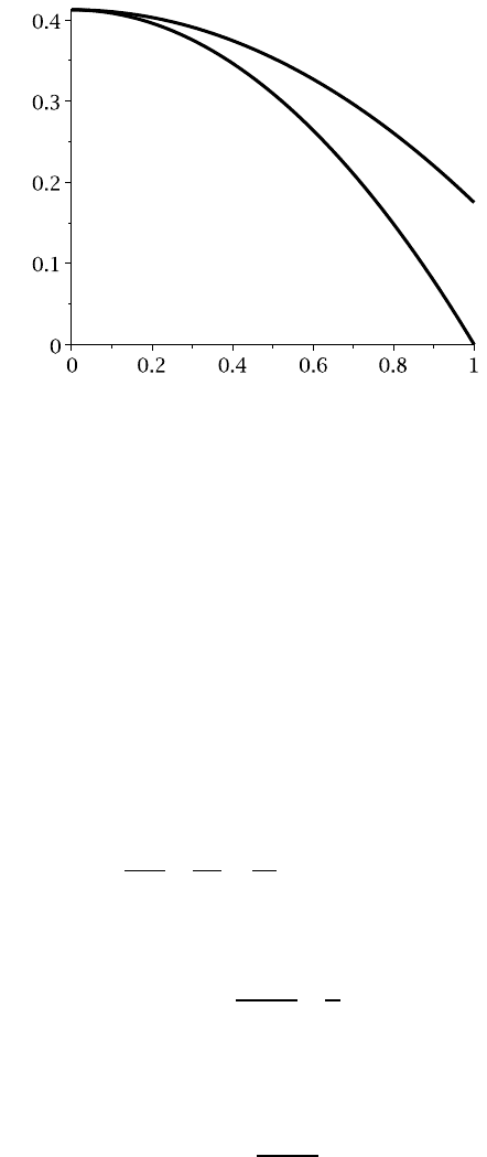
This stress distribution is illustrated in Figure 10.15 for the case where
ν
= 0.3.
Both stresses are tensile throughout the disk and, since the third principal stress
σ
zz
=
0 for the disk, the greatest stress difference in the elastic solution is (
σ
θθ
−
σ
zz
). First
yield will therefore occur at the centre at a speed
Ω
Y
given by
σ
θθ
=
ρΩ
2
Y
(3 +
ν
)a
2
8
= S
Y
,
i.e.
Ω
Y
=
s
8S
Y
(3 +
ν
)
ρ
a
2
.
474 10 Thick-walled Cylinders and Disks
ρΩ
2
a
2
σ σ
θθ
σ
rr
r/a
Figure 10.15: Elastic stress distribution for the rotating solid disk (
ν
=0.3)
The plastic zone
If the speed is increased beyond
Ω
Y
, a plastic zone will develop at the centre. In other
words, the region 0≤r<c will be plastic and the region c<r<a will be elastic, where
c is an unknown radius to be determined.
In the plastic zone 0 ≤r < c, the elastic stress distribution of Figure 10.15 leads
us to expect yielding to be governed by the condition
σ
θθ
−
σ
zz
=S
Y
and hence
σ
θθ
= S
Y
,
since
σ
zz
= 0.
Substituting this result into the equation of motion (10.3), we obtain
d
σ
rr
dr
+
σ
rr
r
=
S
Y
r
−
ρΩ
2
r ,
whose general solution is
σ
rr
= S
Y
−
ρΩ
2
r
2
3
+
C
r
,
where C is an arbitrary constant. The plastic zone includes the centre r=0 and hence
we must have C =0 for the stresses to be bounded, leaving
σ
rr
= S
Y
−
ρΩ
2
r
2
3
.