Barber J.R. Intermediate Mechanics of Materials
Подождите немного. Документ загружается.

Problems 175
Figure P3.36
Invert the matrix to find the corresponding compliance matrix C. Notice that C
is a full matrix, whereas K is banded. Verify that both matrices are symmetric and
that the inequalities (3.80, 3.83, 3.84) are satisfied for this case.
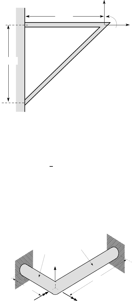
3.37. The pin-jointed bars in Figure P3.37 have a circular cross section of diameter 10
mm and are made of steel with Young’s modulus E =210 GPa. Find the 2×2 stiffness
matrix for the system relating the forces F
1
,F
2
and the corresponding displacements
u
1
,u
2
. You might find it helpful to review the kinematics of Example 3.5 and Figure
3.12.
0.5 m
0.5 m
1
F
1
u ,
2
u
2
F,
Figure P3.37
3.38*. The structure shown in Figure P3.38 consists of two circular steel bars, each
of diameter 10 mm, built in at B,C and welded together at A. Use equations (3.89,
3.90) to construct the 3×3 stiffness matrix relating the forces and moments F
1
,F
2
,M
and the corresponding displacements u
1
,u
2
,
θ
. For steel, E =210 GPa.
We recall from §3.3.2 that bars are much stiffer in extension than in bending.
Discuss the implications of this result in the present problem.
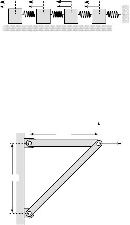
2k
3k
4k
k
1
u
2
u
3
u
4
u
1
F
2
F
3
F
4
F
176 3 Energy Methods
0.5 m
1
F
1
u ,
2
u
2
F,
0.5 m
θ , M
A
B
C
Figure P3.38
3.39. The strain energy in a structure can be written in terms of the stiffness matrix
and the displacements in the form
U =
1
2
N
∑
i=1
N
∑
j=1
K
i j
u
i
u
j
.
Use scenarios analogous to those used in §3.8.2 to establish inequalities that must
be satisfied by the coefficients K
i j
of the stiffness matrix.
3.40. Use equations (3.89, 3.90) to construct the stiffness matrix for the built-in angle
of Figure P3.40 subjected to out-of-plane loading F and moments M
1
, M
2
. Notice
that the coordinate system used here differs from that used in equations (3.89, 3.90).
F,u
EI
1
1
M ,θ
1
GK
2
EI
2
GK
1
2
M ,θ
2
L
2
1
L
,
,
Figure P3.40
Problems 177
Section 3.10
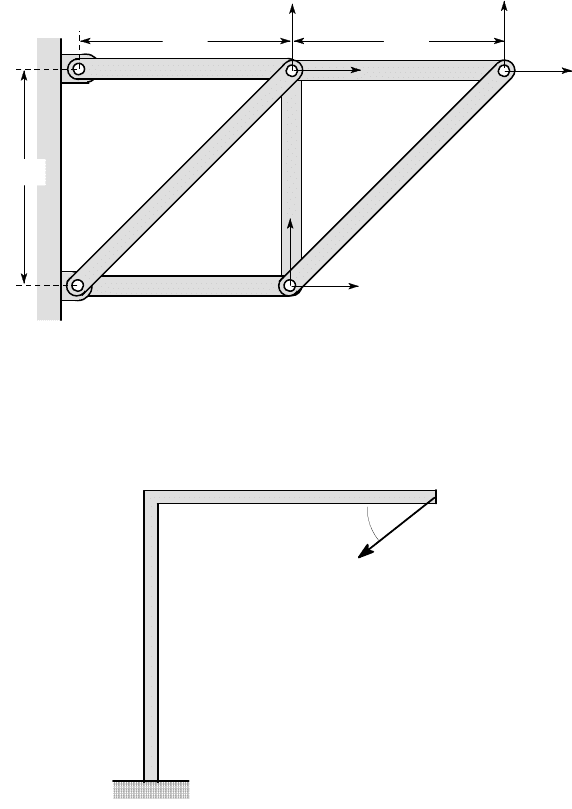
3.41. The bars in Figure P3.41 are each made of steel of cross-sectional area A = 1
in
2
. Use the result given in Problem 3.3 to express the total strain energy stored in
the structure as a function of the displacement components, u
i
, i= (1,6). Hence find
the 6 ×6 stiffness matrix relating the forces F
i
and the corresponding displacements
u
i
. Remember that any given product term (e.g. u
3
u
4
) occurs twice in the sum and
that K
i j
=K
ji
. For steel, E =30 ×10
6
psi.
1
F
1
u ,
2
u
2
F,
10 in
10 in
10 in
u
3
F
3
,
F
4
,
u
4
u
5
F
5
,
u
6
F
6
,
Figure P3.41
3.42. Both segments of the angled beam in Figure P3.42 have the same flexural
rigidity EI and length L.
C
A
B
α
F
Figure P3.42
178 3 Energy Methods
Find the angle
α
if the displacement of the point A is to be in th e same direction
as the force F.
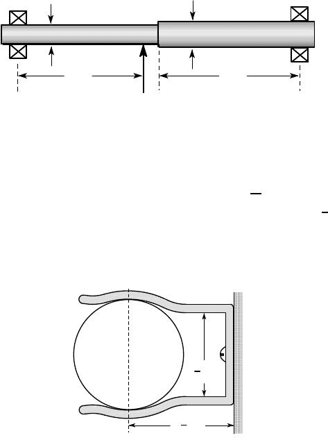
3.43. Figure P3.4 3 shows a stepped steel shaft supported in bearings at A,C and
loaded b y a 2 kN force at B. Use Castigliano’s second the orem to find the angu-
lar misalignment at the bearings (i.e. th e local slope of the beam) due to the shaft
deflection. For steel, E = 210 GPa.
15
25
30
A
B
200
200
C
2 kN
all dimensions in mm
Figure P3.43
3.44. Figure P3 .44 shows a tool clip which is made of 1 ×
1
32
inch spring steel plate,
for which E =30 ×10
6
psi,
ν
=0.3. The separation between the grips is
7
8
inch in the
undeformed po sition and diameter of the tool handle is 1 inch. If the coefficient of
friction is 0. 3, what is the maximum weight of tool that can be supported in a vertical
position.
Tool
1
4
1
in
7
8
in
Figure P3.44
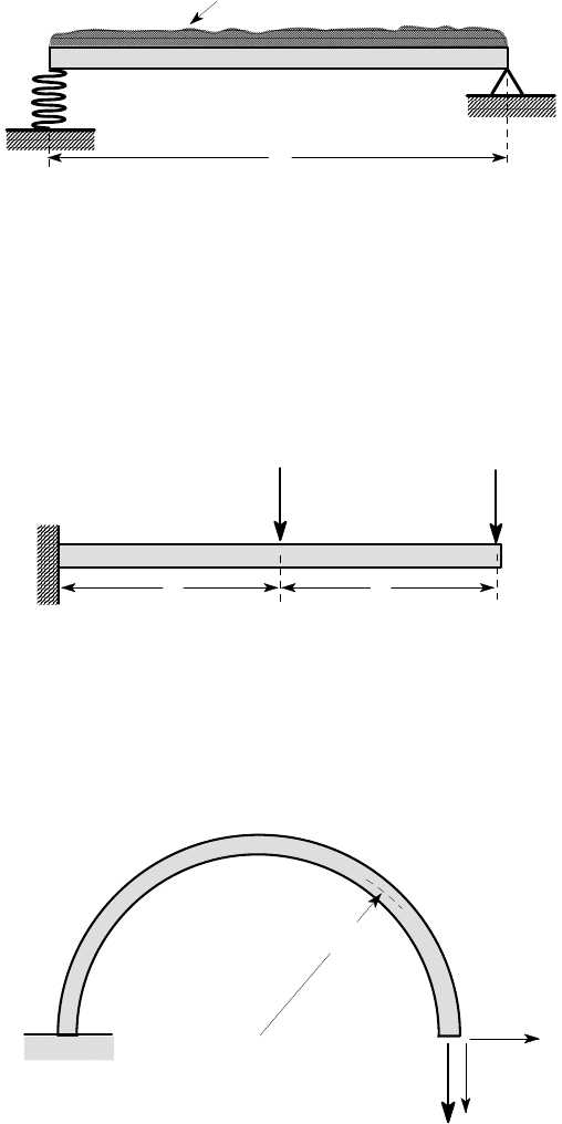
3.45. Fig ure P3.45 shows a beam of length L and flexural rigid ity EI, which is simply
supported at B and supported by a spring of stiffness k at A. Find the slope of the
beam at A when th e beam is subjected to a uniformly distributed loa d w
0
per unit
length.
Problems 179
3.46. A student, asked to compute the downward vertical displacement u
C
at C for
the beam in Figure P3.46, equates it to the partial derivative
∂
U/
∂
F, where U is
the strain energy of the beam. Why is this an incorrect application of Castigliano’s
second theorem? Use the theorem to calculate the correct value of u
C
, if the beam has
flexural rigidity EI and length 2L. What is the physical interpretation of the incorrect
result
∂
U/
∂
F?
A
B
C
F
F
L
L
Figure P3.46
3.47. A thin semi-circular beam of radius R and flexural rigidity EI is subjected to a
vertical force F at the end, as shown in Figure P3.47. Find the horizontal and vertical
components (u
A
,v
A
respectively) of the displacement at the point A.
A
B
F
R
u
A
v
A
Figure P3.47
w per unit length
0
A
B
k
L
Figure P3.45
180 3 Energy Methods
3.48. Use Castigliano’s second theorem to obtain the exact solution for the change in
diameter BD in Problem 3.27.
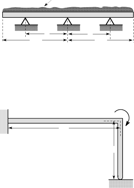
3.49. Figure P3.49 shows a uniform beam subjected to a uniformly distributed load
over its entire length, L. The beam rests on three equally spaced simple supports. Use
Castigliano’s second theorem to determine the distance a between the supports if the
load is to be shared equally between them.
3.50. The right-angle bar of Figure P3.50 is built in at A and rests on a frictionless
support at C. Both segments of the bar have flexural rigidity EI. Use Castigliano’s
second theorem to find the horizontal displacement at C, when the bar is loaded by a
moment M
0
at B.
A
B
C
M
0
2L
L
Figure P3.50
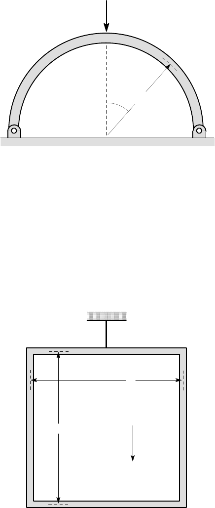
3.51. Figure P3.51 shows a semi-circular curved beam of radius R and flexural rigid-
ity EI, which is pinned at A,C and subjected to a vertical load F at B. Use Cas-
tigliano’s second theorem to find the reactions at the supports and the displacement
under the load.
a
a
w per unit length
0
L /2
L /2
Figure P3.49
Problems 181
A
B
C
F
R
θ
Figure P3.51
3.52. Use Castigliano’s second theorem to find the reaction at the simple support in
Problem 3.20 and hence to find the deflection at the free end of the beam.
3.53. The L ×L square frame of Figure P3.53 is made from solid circular section bar
of diameter d. It is suspended from the mid-point of the upper segment and loaded
only by self-weight. Find the magnitude and location of the maximum tensile stress
if the material has Young’s modulus E and density
ρ
.
g
L
L
Figure P3.53
182 3 Energy Methods
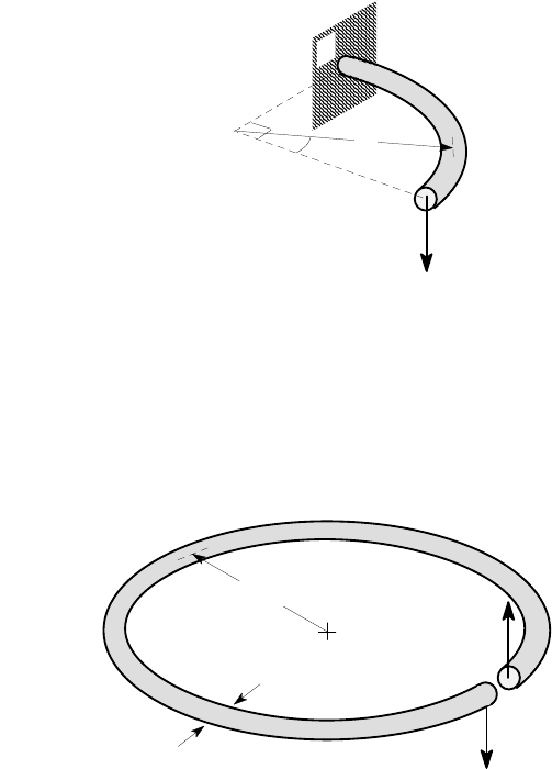
3.54. The curved beam of Figure P3.54 is built-in at A and subjected to an out of
plane load F at B as shown. Find the bending moment M and torque T as functions
of
θ
and hence determine the out of plane displacement at B. The beam has flexural
rigidity EI and torsional rigidity GJ.
F
B
θ
R
A
Figure P3.54
3.55. Figure P3.55 shows an open circular ring of mean radius 30 mm, whose cross
section is a circle of diameter 2 mm. The two ends of the ring are subjected to equal
and opposite 4 N forces out of the plane of the ring. Find the relative displacement
of the two ends, if the ring is made of steel (E =210 GPa,
ν
=0.3).
2 mm
4 N
4 N
30 mm
Figure P3.55
3.56*. Figure P3.56 shows two views of an outboard mounted spur gear that is sub-
jected to a maximum force of 5 kN, which can be assumed to act half way along the
length of the gear. The bearings can be treated as simple supports at their mid-point.
Use Castigliano’s second theorem to estimate the misalignment of the gear teeth
due to shaft deflection, assuming the meshing gear is perfectly aligned and does not
deflect. The shaft is made of steel for which E = 210 GPa,
ν
=0.3. Which end of the
gear will carry the most load as a result of this deformation?
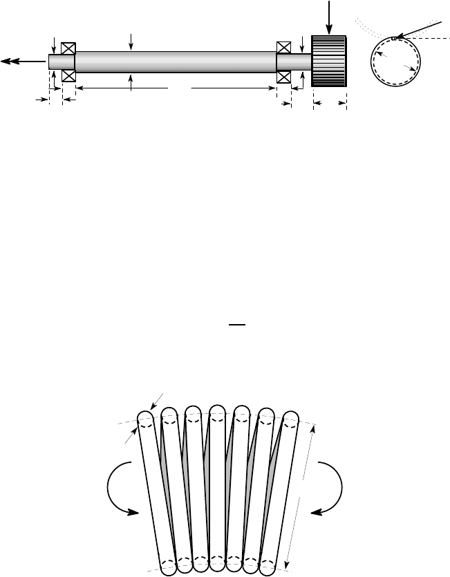
Problems 183
Do you think your answer is sufficiently large to cause concern if the gear design
were based on the assumption of uniform contact along the length?
15
15
15
25
200
40
35
25
30
T
A
B
5 kN
20
o
75
all dimensions in mm
Figure P3.56
3.57*. A long coil spring of mean coil diameter 20 mm is fabricated from steel wire
of diameter 2 mm. The spring is close-coiled, which means that the adjacent coils
touch in the unloaded state. The ends of the coil are now subjected to a bending
moment M, as shown in Figure P3.57.
Find the effective flexural rigidity of the spring — i.e. the constant K
B
in the
relation
M =
K
B
R
,
where R is the radius of curvature of the coil axis due to M. (E =210 GPa,
ν
=0.3).
2 mm
20 mm
M
M
Figure P3.57
184 3 Energy Methods
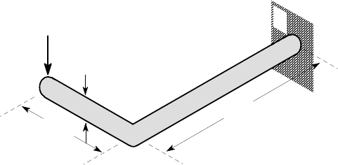
3.58. The right angle crank ABC of Figure P3.58 is made of steel bar of diameter 15
mm and is loaded by an out of plane force of 300 N at the end C.
Find the slope of the bar at C. (E = 210 GPa,
ν
=0.3).
300 N
15 mm
B
C
0.8 m
0.5 m
A
Figure P3.58