ASM Metals HandBook Vol. 14 - Forming and Forging
Подождите немного. Документ загружается.

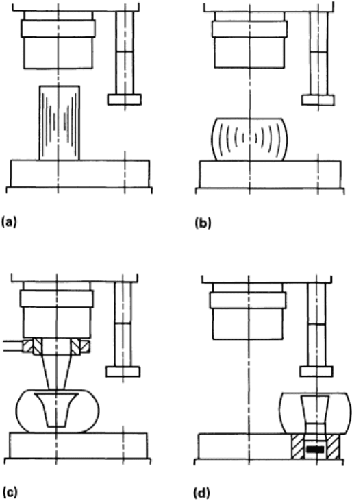
Simply put, the first objective of blank making is to put a hole in the workpiece that is of sufficient diameter to allow the
blank to fit over the rolling mandrel. The diameter of the mandrel has to be such that sufficient force can be applied to
reduce the ring wall section at an acceptable rate. The smaller the hole, the less the material wasted.
Starting material is usually round, although round-cornered-square or octagonal billets can be used. When nonround
material is used, initial working is required to convert it to round stock. Otherwise, the first blanking operation upsets the
billet to reduce height. The second operation consists of indenting with a punch, leaving a thin web at the bottom of the
blank. The third operation punches out this web, creating the doughnut-shaped blank that is ready for rolling. This
sequence is shown schematically in Fig. 25. Although a wide variety of rings can be rolled from blanks made by this
simple process, alternative methods must be used when large ring-height-to-wall ratios are required and for severely
contoured rings with limited rolling reduction (and little diameter growth).
Fig. 25 Schematic showing blank preparation using open dies and a two-
station press. (a) Billet centered on
press table. (b) Billet upset. (c) Upset blank is indented. (d) Blank is pierced and ready for removal.
With thin-wall sleeves, and even with square cross section rings whose mass is very small in relation to the physical
dimensions of the mill, the diameter of the indenting tool may approach that of the upset preform. The indentor then
behaves less like a prepiercing tool and more like a flat die. The result is a grossly distorted and unacceptable blank (Fig.
26) with a height less than that of the rolled ring.

Fig. 26 Blank unacceptably distorted by punch/blank diameter relationship. When the punch diamete
r is too
large in relation to block diameter, it deforms the blank rather than indenting it.
This problem can be overcome either by employing well-tried but slow open-die forging techniques or by indenting the
workpiece in a container. The former requires pressing with a loose small-diameter punch. The blank with punch
entrapped is then turned onto its outside diameter and forged incrementally so that the inside diameter expands and the
height increases.
The use of this method when the press forms part of an integrated line severely curtails output. By using a larger-capacity
press and container dies, excellent blanks can be produced at a rate sufficient to maintain full ring mill production. For
example, a mill that is rolling rings weighing up to 2000 kg (4400 lb) and using open-die forming blanks from a 15.7 MN
(1760 tonf) hydraulic press would require the service of at least a 24.5 MN (2750 tonf) press using container dies to
maintain full production on this type of ring.
Figure 27 shows schematically the sequence of operations on a two-station press using a lower container die located in a
bolster. A fundamental requirement here is the ease in ejecting the workpiece from the die, using a hydraulic cylinder
housed in the lower portion of the press frame. Figure 28 illustrates the use of a two-station press with a shaped upper die
to produce blanks for rolling into weld-neck flanges.
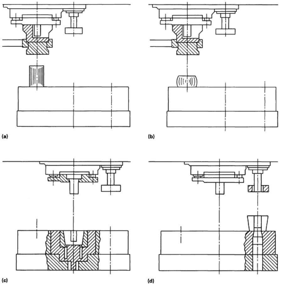
Fig. 27
Manufacture of blanks in a lower container die. (a) Billet centered on press table. (b) Billet is upset. (c)
Blank is indented and formed by backward extrusion. (d) Blank is pierced and ready for removal.
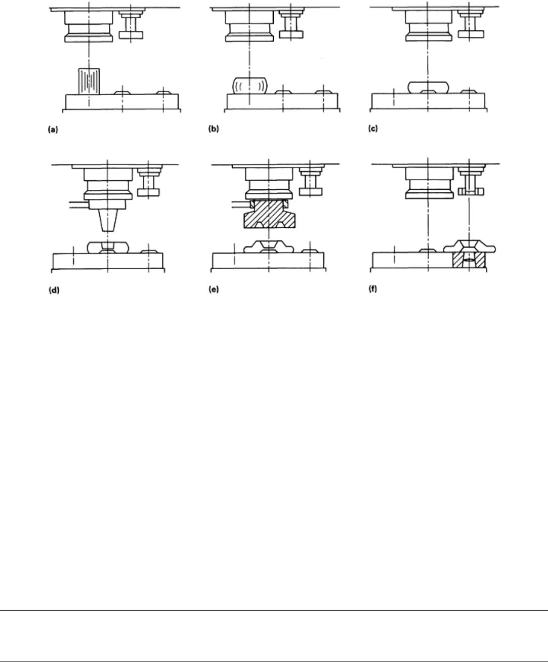
Fig. 28 Manufacture of blanks in a two-
station press using profile tools. (a) Billet centered on press table. (b)
Billet is pre-upset. (c) Billet is upset. (d), (e), and (f) Blank is indented, formed, and pierced, respectively.
On smaller, high-speed ring mills, a three-station blanking press with an integral workpiece transfer system is required to
maintain an adequate supply of blanks. These presses can produce open-die blanks, container-die blanks, and split-die
contoured blanks.
Typically, the less demanding operations of initial breakdown and final piercing, which are carried out off-press-center,
are done simultaneously on two workpieces. The higher-load main forming operation (indenting, container-die forging,
and so on) is done at press center in isolation. Therefore, a block of raw material is loaded on alternate strokes of the
press.
A 9.8 MN (400 tonf) press, serving a 390 kN (44 tonf) radial/310 kN (35 tonf) axial mill can produce up to 250 pieces per
hour in this manner. On very small rings, all three stations of a three-station press can be used simultaneously, producing
one blank per press stroke. This particular press and mill combination can then produce around 300 rings per hour.
Using a modular bottom bolster and top tool holder, tooling can be set up outside the press, and tool sets exchanged in
approximately 20 min, thus maximizing the production time available. A wide range of complexly shaped blanks, which
may be necessary for rolling rings with complex contours, can be produced using split dies by combining various top and
bottom tools at the center station of the press.
Ring Rolling
C.R. Keeton, Ajax Rolled Ring Company
Ancillary Operations
Ring rolling mills must be supported by an array of ancillary equipment. Most important is a means of forming blanks--
usually hammers or presses.

Cutting of Billets. Some method of accurately cutting raw material to the required input weight is necessary. Cold and
hot shearing are employed; the latter is usually used when an integrated production line is involved. Circular saws, which
are sometimes carbide tipped, tend to predominate. Band saws are often used, particularly on stainless steels, and abrasive
saws are used on titanium alloys and superalloys. Blocks for railroad wheels are often cut from ingots on multiple-tool
special-purpose lathes, flame cut or flame nicked, and then fractured on a large press.
Heating. Reheating of cut blocks is usually done in box or rotary fossil-fuel furnaces. Induction heating is sometimes
used for smaller stock and has the advantage of minimal scale formation. Various methods of hot block descaling are
employed, both mechanical (for example, flailing cable, chains, or rotating brushes) and high-pressure (14 to 90 MPa, or
2 to 13 ksi) water spray, which is particularly effective.
Other Operations. Some shops employ devices for sizing rings immediately after rolling. These can be straightforward
hydraulic presses, in which the ring is forced through a circular sizing die, or complex more expanders, which stretch a
ring by applying force to multiple, appropriately shaped segments acting on the inside diameter of a ring.
Appropriate heat treatment facilities are necessary, whether to render the product more easily machinable or to achieve
the mechanical properties specified for the end product. Shotblasting is often used to remove scale formed during hot
working. The resulting surface is easier to inspect and to machine.
Ring Rolling
C.R. Keeton, Ajax Rolled Ring Company
Blanking Tools and Work Rolls
Although hot-work tool steels such as H11 and H13 are frequently used for blanking and rolling tools, especially when
working heat-resistant alloys, less expensive alloy steels such as AISI 4140 and AISI 4340 find wide application on less
demanding work materials. Various types of blanking and rolling tools are shown in Fig. 29.
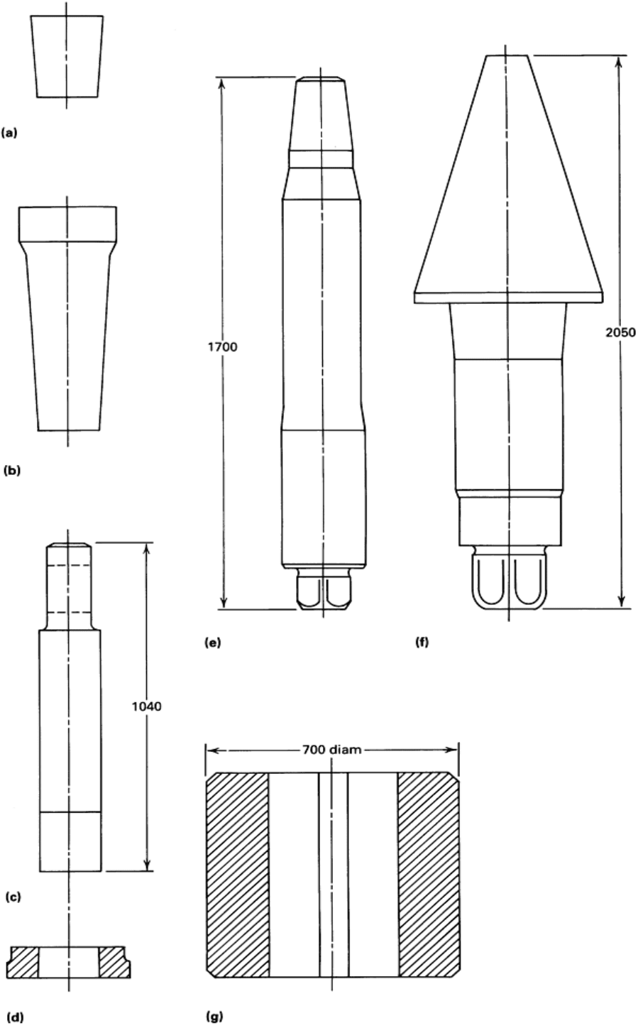
Fig. 29 Blanking and rolling tools used in ring rolling. (a) Tapered indenting
punch. (b) Tapered, swing arm
mounted indentor. (c) and (d) Piercing punch and support ring for a blanking press. (e) Typical mandrel for a
mid-size mill. (f) Axial roll. (g) Main roll. See text for discussion of tool materials.
Dimensions given in
millimeters (1 in. = 25.4 mm).
When blanks are open-die forged on hammers or presses, simple tapered indenting punches (Fig. 29a) are driven into the
preform. The preform is then turned over, allowing the punch to fall out, and the punch is then used to cut out the slug
remaining from indenting, thus forming the doughnut-shaped blank.
A wide range of punch diameters and lengths are typically available to accommodate the many different blank dimensions
required. With several punches in each size and each cooled in water immediately after use, AISI 4140 or AISI 4340 are
quite adequate in terms of life and cost. If special-purpose ring blank presses are used, tool duplication is usually not
feasible, and short periods of cooling between each blanking operation may not be sufficient to allow the use of the
regular alloy steels above.
Figure 29(b) shows a 3° tapered, swing arm mounted indentor typically used in blanking presses. A low-alloy steel such
as ASM 6F2 (see the article "Dies and Die Materials for Hot Forging" in this Volume) at 38 to 43 HRC (350 to 400 HB)
may be necessary to withstand the higher tool working temperature.
Figures 29(c) and (d) show the type of piercing punch and support ring that would be used on a two- or three-station
blanking press to shear out the slug created by indenting. Almost invariably, the punch is either solid H13 or has an
exchangeable tip in H13 heat treated to about 49 HRC (460 HB). The support ring is also usually made of H13. Typically,
the radial clearance between the punch and the support ring is of the order of 2 to 5 mm (0.008 to 0.2 in.) for punches 125
to 220 mm (5 to 8.7 in.) in diameter. On high-speed blanking presses, the indenting punch in the center station is so
heavily used that even when it is made of H13, continuous internal water cooling is necessary, along with inter-cycle
external water-spray cooling.
Container dies used on a slower-speed, larger press (for example, 24.5 MN, or 2750 tonf, capacity) can often be made
from AISI 4140 or 4340 if the duty cycle is long enough and inter-cycle water cooling is adequate. Inserts fabricated from
H13 tool steel may be necessary on smaller blanks with shorter cycle times.
On presses where no means are available for stripping blanks off (indenting) punches, these punches typically have a
taper of 3° per side. Powdered coal or waterborne graphite lubricants are usually employed to ensure release of the punch
from the blank. Where stripping mechanisms (depending on the type) are available to eject the blank, release tapers of
about 1° can be employed for both punches and containers.
The consumable tools on radial-axial ring rolling mills are principally the mandrel and, to a lesser extent, the axial
(conical) rolls and the main roll. Depending on the mill design and force capability, mandrels may be as small as 30 mm
(1.2 in.) in diameter (for a 295 kN, or 33 tonf, mill) and as large as 450 mm (18 in.) in diameter for a mill with a radial
capacity of 5 MN (550 tonf).
Figure 29(e) shows a typical 165 mm (65 in.) diam mandrel for a midsize mill with 980 kN (110 tonf) radial capacity.
Such mandrels are commonly fabricated from ASM 6F3 at 370 to 410 HB. Again, AISI 4340, at 300 to 350 HB, with
adequate water-spray cooling, can be used with good results (that is, producing up to 3000 rings before failing through
heat check initiated fatigue). Production of 1500 to 2000 rings can be expected from a 70 mm (2.75 in.) H13 tool steel
mandrel used on a high-speed multiple-mandrel mill of 390 kN (44 tonf) radial capacity.
Axial rolls (Fig. 29f) on older machines typically had a 45° included angle, along with relatively short working lengths.
This severely limited the ring wall thickness they could cover and led to rapid wear of the conical surfaces. With the
resultant need to change axial rolls frequently, two part designs were often employed with the working cone bolted to a
semipermanently installed roll shaft.
Modern machines have 30 to 40° included-angle axial cones and longer working lengths. Wear is spread over the greater
length, and roll changes are required less frequently (for example, after 600 to more than 1000 h of use).

Axial rolls are usually one-piece designs; AISI 4140, ASM 6F2, and ASM 6F3 are typical materials. These rolls are
usually welded and reworked to original dimensions many times before being discarded. Extended service life can be
obtained by using a cobalt-base hardfacing alloy, approximately 1.5 mm (0.06 in.) thick, on the working surfaces on these
axial cones.
Figure 29(g) shows a typical AISI 4140 main roll for a 980 kN (110 tonf) radial capacity ring mill. Such rolls tend to wear
most heavily at the point where the bottom corner of the ring is contacted. To prolong use between roll changes, the roll
and shaft assembly are periodically adjusted downward from maximum height setting gradually toward minimum,
typically over a full range of 30 mm (1.2 in.).
In addition to ensuring maximum roll life, they are initially made to an acceptably larger-than-nominal diameter and are
recut at intervals until the minimum mandrel/main roll gap is unacceptable. At this point, if economical, weld repair and
hardfacing can be employed.
Ring Rolling
C.R. Keeton, Ajax Rolled Ring Company
Combined Ring Rolling and Closed-Die Forging
The combination of ring rolling machines and closed-die hammers or presses in integrated manufacturing cells yields a
degree of flexibility and economic benefit not achievable by either process separately. With sufficient ingenuity applied to
equipment layout and handling devices, a number of process sequences can be used; the final component forming occurs
either on the ring mill or the closed-die unit, depending on the particular component shape and size.
Figure 30 compares the equipment required and the economics of producing a starter ring by closed-die forging and ring
rolling combined (Fig. 30a) and by closed-die forging only (Fig. 30b). Similarly, Fig. 31 shows the comparison for weld-
neck flange forming.
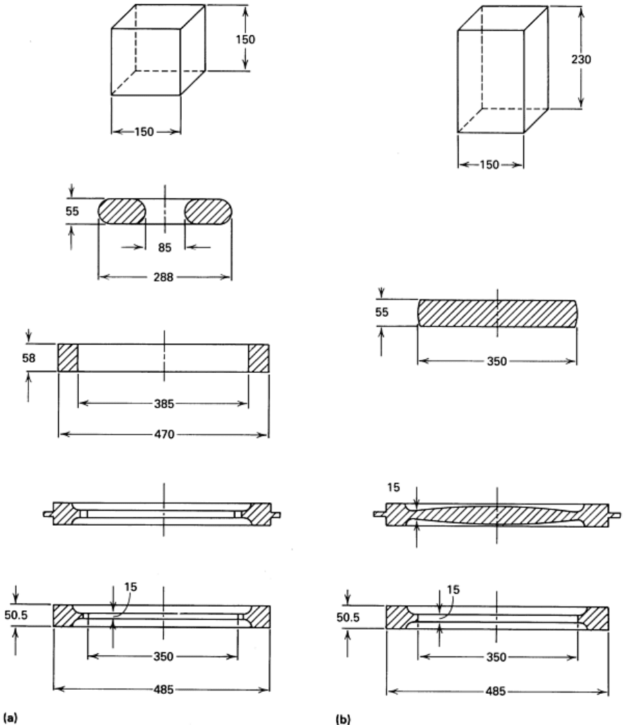
Fig. 30 Comparison of closed-die forging plus ring rolling (a) and closed-
die forging only (b) for the production
of a starter ring. (a) Top to bottom: billet, pierced blank, rolled ring, die forging, and finished part. (b) T
op to
bottom: billet, upset disk, die forging, and finished part. Although an additional step is needed when ring rolling
is used, the production rate increases from 70 to 110 pieces per hour, and a material saving of 38% per piece
is realized. Dimensions given in millimeters (1 in. = 25.4 mm).
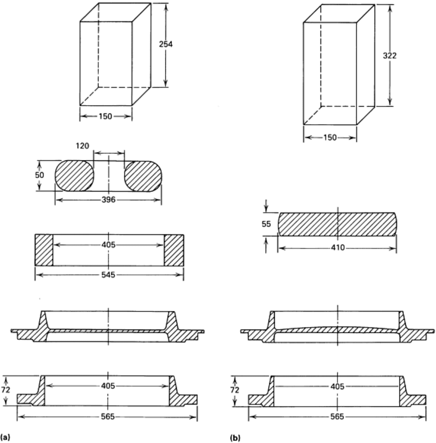
Fig. 31 Comparison of closed-die forging plus ring rolling (a) and closed-die forging
only (b) for the production
of a weld-neck flange. (a) Top to bottom: billet, pierced blank, prerolled ring, finish-
forged part, and trimmed
part. (b) Top to bottom: billet, upset disk, finished forging, and trimmed part. Production rate doubled and a
material savings of 21% per piece was realized when the ring rolling process was used.
Dimensions given in
millimeters (1 in. = 25.4 mm).
From these examples, it can be seen that for a given production program new installations can be equipped with
appreciably smaller principal forming equipment. Furthermore, despite the additional number of pieces of equipment, the
total investment is usually lower than if a 100% closed-die approach were selected. Alternatively, the addition of a ring
roller to an existing closed-die plant can extend the production range to substantially larger pieces.
By avoiding large inside flash formation, material input can be reduced by 15 to 35% (Fig. 30 and 31). Production rates
10 to 40% higher than closed-die forging can be achieved through simultaneous operations performed in more, but
individually less demanding, steps. The much-reduced inside flash means lower stock-heating costs, and approximately
50% less deformation energy is required at the closed-die stage. The number of operators required usually remains
unchanged.
Bevel Gear Manufacture. Figure 32 illustrates five possible methods of manufacturing large bevel gears. Table 3 lists
the start/finish material weight relationships for these methods. The capital investment and material yield benefits of ring
