ASM Metals HandBook Vol. 14 - Forming and Forging
Подождите немного. Документ загружается.


the dome. The piece was drawn from a 280 mm (11
1
8
in.) diam blank produced in operation 1 (not shown).
Dimensions in figure given in inches.
The stock was 289 mm (11.375 in.) wide annealed type 304 stainless steel strip, 1.1 mm (0.042 in.) thick. A single-action
mechanical press with a spring-loaded pressure pad was used to cut 280 mm (11
1
8
in.) diam blanks from the strip,
leaving 3.2 mm (
1
8
in.) minimum scrap on each side of the strip.
The first draw was made in a 2200 kN (250 tonf) double-action mechanical press. The punch was 83 mm (3
1
4
in.) in
diameter; therefore, much of the surface of the dome was drawn free (operation 2, Fig. 19). This required careful control
of the blankholder pressure to prevent puckers and wrinkles. Blankholder pressure had to be adjusted for every lot of
steel; it varied from 5.5 to 6.9 MPa (0.8 to 1.0 ksi). The die radius also had to be held closely (5.2 times the stock
thickness). The first draw produced a cup 175 mm (6
7
8
in.) in diameter with a 235 mm (9
1
4
in.) diam flange.
The second draw was also made in the 2200 kN (250 tonf) double-action press. The punch for the second draw was
shaped to the required inner contour of the part, including the step at the base of the dome, which was formed as the press
bottomed at the end of the second draw stroke (operation 3, Fig. 19). This operation formed the dome shape of the bottle
top by reshaping (mostly by stretching) the cup formed in the first draw. The metal for the cylindrical area above the step
was drawn from the flange metal remaining after the first draw.
In the fourth operation, the hole in the top of the dome was pierced, and an internal stretch flange was formed around the
hole. This was done with a spring-loaded piercing die, which gave sufficient resistance to let the piercing punch shear the
material and then retreat under pressure from the flange-forming part of the punch. Both ends of the part were later
trimmed in a lathe.
Drawing Rectangular Parts. During the deep drawing of a box-shaped part, the metal in the corners of the part and
in the flange around the corner undergoes a change much like that which takes place when a round shell is drawn from a
circular blank. Metal is compressed at the corners, and significant thickening occurs where the metal flows into the
corners. The sides of the box undergo essentially no thickening, because there is no compression of the metal in the flange
areas as it flows or bends over the die radius.
Clearances in the sides between the punch and die are ordinarily about 10% greater than the metal thickness to
compensate for gage variations and to allow for metal flow. At the corners, punch-to-die clearances are similar to those
used for cylindrical parts to allow for thickening.
Blankholding devices are almost always used in producing deeply recessed box-shaped parts in order to control the metal
movement, particularly in the corners. The corners are under severe strain because of the intense compression of the
flange metal, and most fracturing, if it does occur, takes place in the lower wall corner sections.
Punch and die radii are generally the same for rectangular draws as for circular draws. Some fabricators prefer to make
the punch and die radii at the corners larger than along the sides in order to equalize the stress in the metal at the corners.
The top surface of the draw die and the draw radii should be polished smooth (free of grind marks and well blended) to
prevent localized retardation of metal flow with resultant uneven drawing of the metal. Burrs and bent edges on the blank
often restrict metal flow or movement along the blankholder surface to such a degree that vertical wall fractures can
occur.
Semideveloped blanks usually produce better results than rectangular ones. There are a number of patterns for trimming
the corners, ranging from a simple 45° trim to patterns with a carefully developed area containing the optimal volume and
area of metal.
The economic success of the run is related to tool wear and scrap rate. The following example describes a combination of
tool materials that has given satisfactory performance in terms of parts or draws per regrind and redress. The same tooling
can be used for both drawing operations, with the draw ring reversed to present a different radius for the second draw, as
in the following example.
Example 19: Use of a Reversible Two-Radius Draw Ring for Drawing and
Redrawing of a Flanged Rectangular Shell.
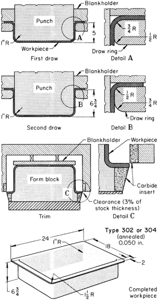
The flat-flanged single-sump kitchen sink shown in Fig. 20 was formed in four operations: blank, draw, redraw, and trim.
Forming of the part was a combined draw-and-stretch operation. Because several different models, with drain holes in
various locations, were made from the same drawn part, the drain hole was not pierced in the trimming operation but was
made separately. The production rate was 50,000 to 100,000 pieces per year.
Fig. 20 Production of a flat-flanged sink basin by drawing and redrawing (using a two-
radius reversible draw
ring) and trimming. Dimensions given in inches.

The material was annealed type 302 or 304 stainless steel coil stock 735 mm (29 in.) wide and 1.27 mm (0.050 in.) thick,
with a No. 2D sheet finish. Blanks 635 mm (25 in.) long were sheared from the coil at the rate of 40 per minute in a
single-action mechanical press. Corners of the blanks were trimmed at 45°, removing 50 mm (2 in.) from each edge of the
blank at each corner. Clearance for this trimming was kept at less than 5% of metal thickness to minimize edge distortion
and burrs.
The draws were made in a 3600 kN (400 tonf) double-action mechanical press with 2200 kN (250 tonf) available for
blank holding. The draw punch was made of alloy tool steel, and the blankholder was made of alloy cast iron. The
reversible draw ring (Fig. 20) was made of hard aluminum bronze and had a 19 mm (
3
4
in.) draw radius on one side for
the first draw and a 13 mm (
1
2
in.) draw radius on the other side for the redraw. The workpiece was annealed in an inert
atmosphere at 1065 °C (1950 °F) between the first and second draws and then air cooled rapidly to room temperature.
The depth of the sink after the first draw was 127 mm (5 in.); after the second draw it was 170 mm (6
3
4
in.). Draws were
made at a punch speed of approximately 6.4 m (21 ft) per minute, with less than 2% of the workpieces fracturing.
A similar 3600 kN (400 tonf) press was used to trim the piece. Carbide inserts provided shearing edges for the trimming
operation. The sink was held on a form block of molded plastic or cast iron for trimming.
The second draw operation sharpened the bottom and flange corner radii and stretched the bottom surface and the side
walls to remove any loose metal. Little or no metal was drawn into the part from the flange during the second draw.
Forming of Stainless Steel
Revised by Joseph A. Douthett, Armco Inc.
Spinning
Stainless steel parts such as cups, cones, and dished heads can be readily formed by manual or power spinning, although
more power is required than that needed for the spinning of low-carbon steel. Equipment and techniques for these
processes are described in the article "Spinning" in this Volume.
Manual Spinning. The amount of thinning that occurs during manual spinning is related to the severity of the formed
shape. A cross section is shown in Fig. 21 of a manually spun piece that thinned out to such a degree that it often
fractured. This piece was excessively worked, and the mid-center area was work hardened beyond the capacity of the
material, causing the workpiece to fracture. The piece was later made by press drawing the dome-shaped cup and
spinning the broad flared flange.
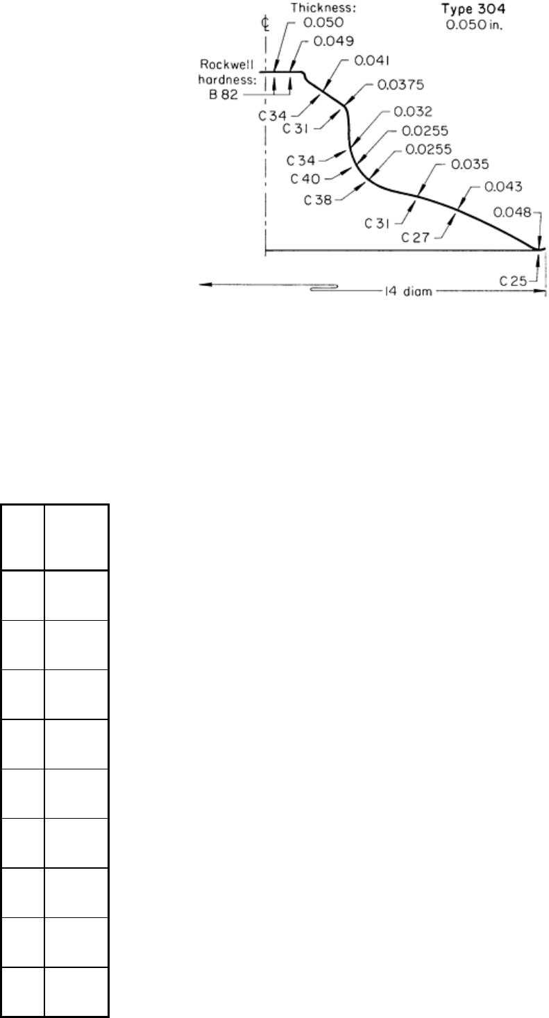
Fig. 21 Pro
file of shape, hardness, and thickness of a manually spun part that often fractured in its thinnest
section. Dimensions given in inches.
The approximate limits of stretch in manual spinning are given in Table 9. These are for 1.57 mm (0.062 in.) thick fully
annealed stock. The second stretch after annealing is about 8% less than the first. The amount of stretch is not necessarily
uniform over the entire part; it varies with the severity of the form.
Table 9 Approximate limits of stretch in the manual spinning of stainless stools 1.57 mm (0.062 in.) thick
Type
Stretch
(max), %
305
45
302
40
304
40
302B
35
316
35
316L
35
321
35
309
30
310
30

317
30
430
30
201
25
202
25
301
25
405
25
446
25
403
20
410 20
These limits are for stretching during one spinning pass; after being annealed, the metal can be respun to 8% less than the first stretch.
Although 300-series stainless steels can be formed by spinning, 302, 304, and 305 can be spun to greater reductions than
other stainless steels before intermediate annealing becomes necessary. All anneals must be followed by pickling to
remove oxides, thus restoring the clean, smooth surface. The No. 1 strip or 2D sheet finish is best for severe applications
because the metal is in the softest stress-free condition and will take the greatest amount of working. The following
example demonstrates the spinnability of type 305 stainless steel.
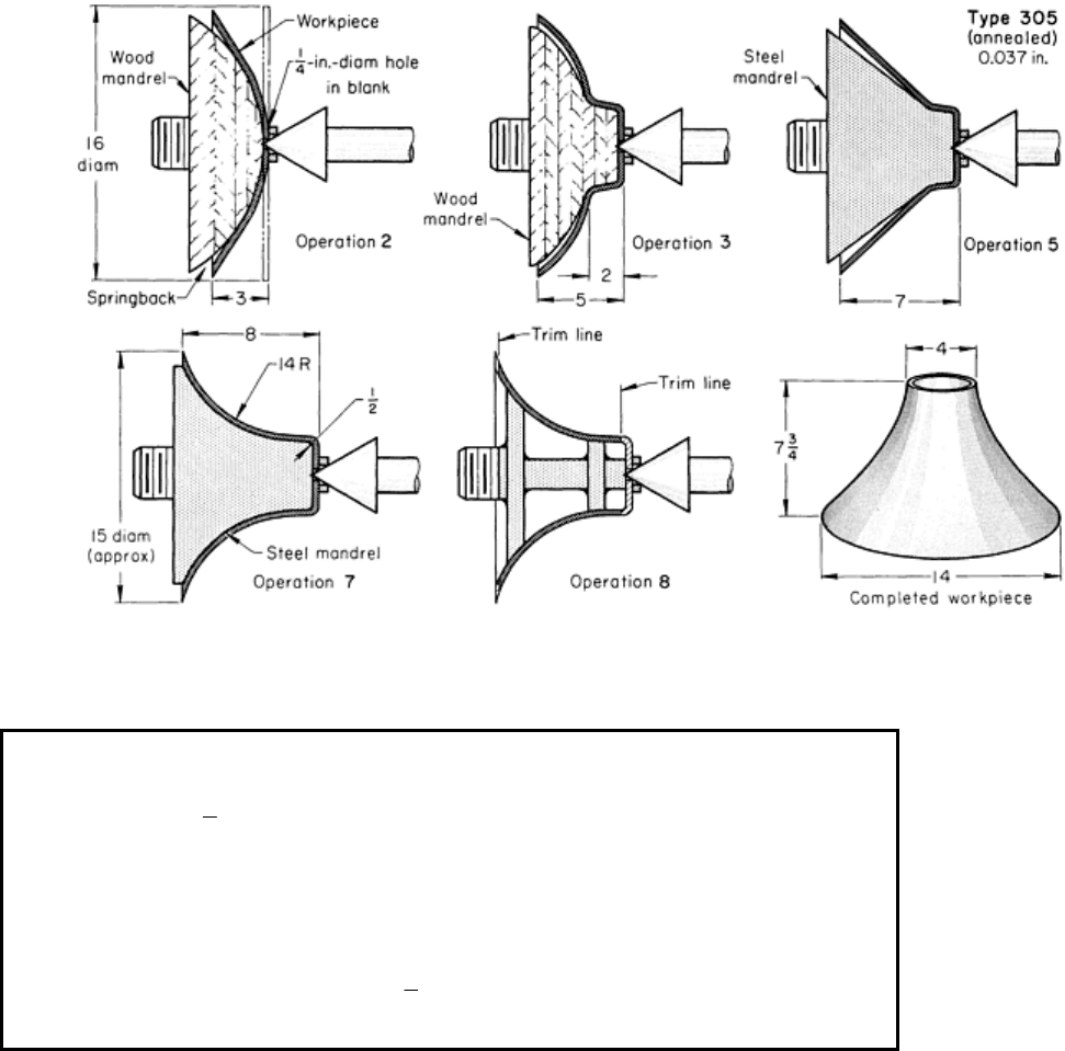
Example 20: Four-Pass Manual Spinning of a Cone From Type 305 Stainless
Steel.
The 355 mm (14 in.) diam cone shown in Fig. 22 was produced in eight operations, including four manual spinning
passes, from a 405 mm (16 in.) diam blank of 0.94 mm (0.037 in.) thick annealed type 305 stainless steel that had a No.
2D sheet finish or a No. 1 strip finish. Other types of austenitic stainless steel could have been used, but the reduction per
pass would have been lower, in proportion to the increase in rate of work hardening.
Sequence of operations
Drill a 6.4 mm (
1
4
in.) diam center hole in a 405 mm (16 in.) diam blank 0.94 mm (0.037 in.) thick.
Spin to 75 mm (3 in.) depth on a laminated hardwood mandrel at 300 rpm, applying manual pressure on lever and roller.
Spin to 125 mm (5 in.) depth on a second laminated hardwood mandrel to within 25 mm (1 in.) of edge.
Anneal in hydrogen atmosphere at 1040 °C (1900 °F); air cool.
Spin to 178 mm (7 in.) depth on a steel mandrel to within 25 mm (1 in.) of edge.
Anneal as in operation 4.
Spin to 205 mm (8 in.) depth and final shape on a steel mandrel.
Lathe-trim top and bottom ends to 195 mm (7
3
4
in.) final height of cone.
Fig. 22 Production of a stainless steel cone by four-pass manual spinning. Dimensions in figure given in inches.
As shown in Fig. 22, the mandrels for spinning were made of wood or steel. The spinning roller was made of hardened
steel. Pressure was applied to the entire blank in the first spinning pass. In the three other passes, the outer 25 mm (1 in.)
of the blank was not spun. This caused the edge to thicken to 1.78 mm (0.070 in.) and helped hold the outer shape.
Thinning was greatest at the middle of the cone, to about 0.69 mm (0.027 in.) wall thickness (28% reduction). The surface
area of the piece was increased 40%. The drastic working that accompanied the thinning and the increase in area made
two anneals necessary (see sequence of operations, Fig. 22). Annual production quantity was 500 pieces.
The 400-series stainless steels, because of their relatively low ductility, do not adapt readily to manual spinning,
especially when the deformation is severe. The high pressure of the forming tool causes wear of the work metal, resulting
in early thinning and fracturing. Figure 23 shows forming speeds used for manual spinning of 400-series stainless steels.
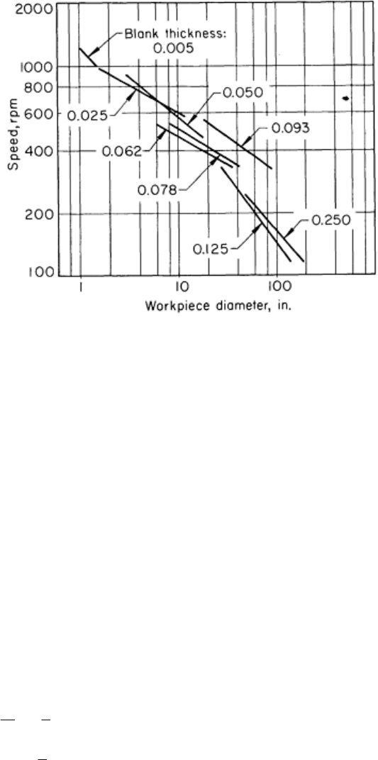
Fig. 23 Effect of workpiece diameter and bla
nk thickness on rotational speed for the manual spinning of
austenitic stainless steel. Dimensions given in inches.
The surface of severely spun parts is often very rough because of the action of the tools on the metal, and the production
of a buffed or highly polished finish on a part spun from a 400-series stainless steel can be expensive. It is generally
necessary to rough grind the material to smooth out the irregularities before polishing and buffing.
Typical stock thicknesses of stainless steel for manual spinning are 0.30 to 3.18 mm (0.012 to 0.125 in.), although
stainless steels as thin as 0.13 mm (0.005 in.) and as thick as 6.35 mm (0.250 in.) have been spun by hand. The corner
radius should be at least five times the thickness of the work metal. Allowance must be made in the size and shape of
mandrels for springback and for heat-induced dimensional changes.
Power spinning is used for severe reductions and for work that cannot be done by hand. Stainless steels in both the 300
and 400 series are readily formed by power spinning, but the low-work-hardening types 302 and 305 are superior. Much
larger reductions of type 430 can be made by power spinning than by manual spinning.
Spinning can be done hot or cold, although the severe reduction accompanying power spinning may cause so much heat
that the spinning that began cold becomes warm spinning. Hot spinning, done only above 790 °C (1450 °F), is commonly
used for work 4.8 to 13 mm (
3
16
to
1
2
in.) thick. The need for careful control of the temperature makes it difficult to hot
spin metal that is less than 6.4 mm (
1
4
in.) thick. Thicker stainless steel can be hot spun as easily as low-carbon steel.
Cracking at the edge is the main problem in the power spinning of austenitic stainless steels. The edge of the blank may
need to be ground smooth to prevent cracking. A generous trim allowance is helpful so that the cracked edge can be cut
off. Cracking and distortion can be prevented by keeping a narrow flange on the work. If the size of the spun piece is not
correct after it cools (because of springback and heat expansion), the piece can be annealed and spun to size while it is
still above 150 °C (300 °F).
Considerable thinning can be produced by power spinning, as indicated by the cross section of a deeply spun vessel
shown in Fig. 24. The thickness of the vessel was reduced from 1.90 to 0.66 mm (0.075 to 0.026 in.) in one spinning
operation. A preformed cup 152 mm (6 in.) in diameter and 75 mm (3 in.) deep, drawn on a conventional press, was used
as the starting shape. The top of the vessel is much thicker than the wall. Thickening of the rim occurred during drawing,
and it remained thick because there was essentially no deformation in this region during spinning.
Fig. 24
Variations in hardness and thickness of a shell that was power spun from a preform drawn from
stainless steel 1.9 mm (0.075 in.) thick. Dimensions in figure given in inches.
The surfaces of power-spun pieces are rough, and extensive finishing is required to make them smooth and bright. The
spun surface is rough because the roller usually imparts a spiral or helical groove to the surface as the roller is fed into the
metal while it rotates. Except for this disadvantage, power spinning is an excellent way of forming pieces from stainless
steel.
Lubricants (see Table 2) are used to reduce friction, to minimize galling and tool drag, and to provide cooling. For
manual spinning, firmly adherent lubricants are preferred; for power spinning, coolant action is more important.
Lubricants containing sulfur or chlorine are usually avoided; they are difficult to remove completely and have harmful
effects on heated stainless surfaces.
Forming of Stainless Steel
Revised by Joseph A. Douthett, Armco Inc.
Rubber-Pad Forming
Annealed austenitic stainless steels--types 301, 302, 304, 305, 321, and 347--are rubber-pad formed in thicknesses to 1.3
mm (0.050 in.). Most of the operations are straight flanging, especially in thicker workpieces. With auxiliary devices,
such as wedges or rollers, pieces up to 2.0 mm (0.078 in.) thick can be formed. Flanges must be wide enough to develop
adequate forming force from the unit pressure on their surface. For annealed stainless steels, the following minimum
flange widths beyond the bend radius are recommended for successful forming:
Thickness
Flange width

mm
in. mm
in.
0.41
0.016
6.35
0.250
0.51
0.020
6.86
0.270
0.64
0.025
7.37
0.290
0.81
0.032
8.38
0.330
1.02
0.040
9.14
0.360
1.30
0.051
10.0
0.410
1.63
0.064
12.2
0.480
1.83
0.072
13.0
0.510
In quarter-hard temper, types 301 and 302 up to 0.81 mm (0.032 in.) thick can be flanged if the flange is at least 16 mm
(
5
8
in.) wide.
The rubber-pad forming of contoured flanges in stainless steel requires more powerful equipment than that used for flat
flanges. Most forming of contoured flanges is done on annealed stainless steel, but a limited amount is done on quarter-
hard stock.
Stretch flanges are readily formed on annealed stainless steel up to 1.3 mm (0.050 in.) thick. Rubber-pad-formed
stretch flanges of thin metal are generally smoother and more accurately formed than those formed by single-action dies.
Die-formed flanges often curl outward, requiring considerable hand work for correction.
The hydraulic presses used in the Guerin process develop forming pressures to 34.5 MPa (5 ksi). Narrow stretch flanges
that require pressures greater than 34.5 MPa (5 ksi) are formed with the aid of auxiliary devices, such as traps and wedge
blocks, that raise the forming pressure locally (see the article "Rubber-Pad Forming" in this Volume).
Thin metal can be formed by means of a simple form block, but if the web is narrow, the workpiece should be protected
by a cover plate to avoid distortion. The following example demonstrates the limits of rubber-pad forming of stretch
flanges in stainless steel:
• The stock was quarter-hard type 302
• The workpiece had a narrow web and therefore required the use of a cover plate in forming
• The workpiece had external hole flanges
• The stretch flange was only 7.9 mm (
5
16
in.) wide
• The curved workpiece was nearly 965 mm (38 in.) long
If a stainless steel part of this shape is more than 610 mm (24 in.) long, it is almost impossible to prevent the springback
of the flange material from bowing the part unless curved dies are used.
Example 21: Use of a Curved Die With Cover Plates in Rubber-Pad Forming.
The strut shown in Fig. 25 had a 7.9 mm (
5
16
in.) wide stretch flange and external 65° flanges on two lightening holes at
the large end. It was rubber-pad formed from a quarter-hard type 302 stainless steel blank 0.41 mm (0.016 in.) thick.
Fig. 25 Long narrow strut with a contoured stretch flange that was made by rubber-
pad forming in a curved die
with cover plates to prevent springback. Dimensions given in inches.
The zinc alloy die used was made with a curve to offset the springback of the flange (Fig. 25). Right-hand and left-hand
pieces were flanged at the same time in the same die. A steel cover plate protected the thin web of each piece from
distortion during forming. No lubricant was used. The pressure developed by the rubber was 10.3 MPa (1.5 ksi).
Deep Drawing. By the rubber-pad and rubber-diaphragm processes, stainless steels in both the 300 and the 400 series
can be deep drawn to greater reductions than can be achieved with conventional methods. For extremely deep sections,
the lower-work-hardening austenitic types 302 and 305 are recommended.
Two characteristics of rubber-pad methods make this great depth of draw possible. The first is controlled, continuously
adjustable pressure on the blankholder or hold-down mechanism, and the second is the continuously variable draw ring
radius. There is no draw ring as such, but the rubber that forms around the workpiece functions as a draw ring and
conforms to the radius that will apply equal pressure to the entire surface of the workpiece. This minimizes both thinning
at the punch radius and work hardening as the flange metal is drawn into the cup.
Figure 26 illustrates the relatively uniform wall thickness that can be produced by drawing using the rubber-pad method.
For comparison, Fig. 17 shows the much greater variation in wall thickness produced by conventional deep drawing.