ASM Metals HandBook Vol. 14 - Forming and Forging
Подождите немного. Документ загружается.

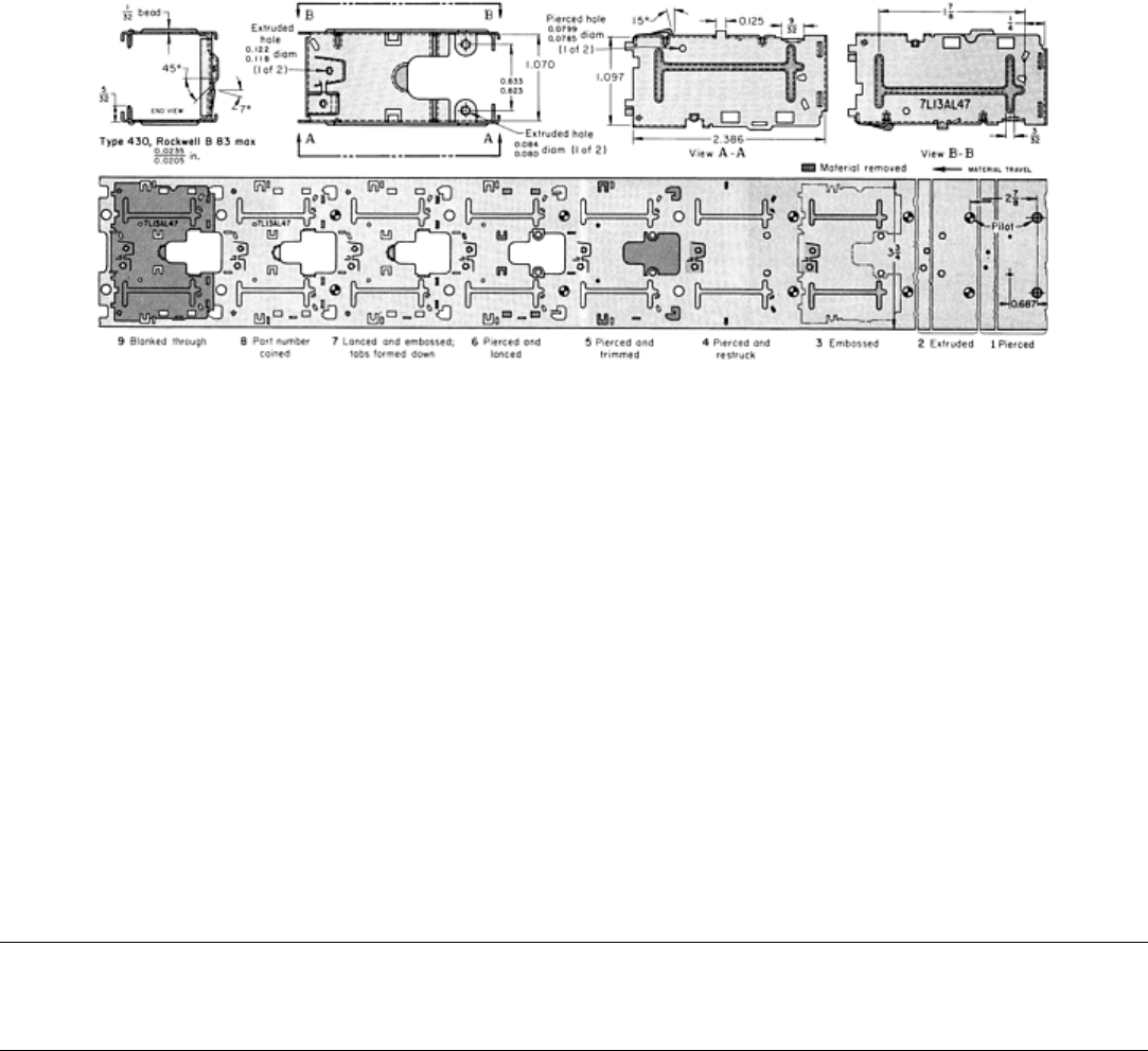
Fig. 13 Frame produced in a nine-
station progressive die in the sequence of operations indicated on the strip
development shown. Final forming was done in separate dies. Dimensions given in inches.
A nine-station progressive die was used to pierce and flange the holes, to emboss the stiffening beads on the two legs, to
trim and form the tabs, to coin identification data, and to blank the part from the strip. Stops were then lanced and formed,
and bottom flanges were formed in a forming die. A final forming die was used for the deep side flanges.
The progressive die was run in a 670 kN (75 tonf) mechanical press at a rate of 5000 pieces per hour. The first and second
forming dies were run in a 270 kN (30 tonf) press at speeds of 984 and 936 pieces per hour, respectively.
Annual production was 90,000 frames, and demand was expected to increase. This, in addition to the short press time
(0.2284 h per 100 pieces, as against an estimated 0.6665 h per 100 pieces if produced in eight separate dies) and the
greater accuracy obtainable in the progressive die, justified the higher tooling cost for the progressive-die method (60%
higher when compared to separate dies).
The dies were made of A2 tool steel and had a life of 50,000 to 75,000 pieces between regrinds. The lubricant was an
emulsifiable chlorinated oil concentrate.
Forming of Stainless Steel
Revised by Joseph A. Douthett, Armco Inc.
Multiple-Slide Forming
Small high-production stainless steel parts can sometimes be formed in multiple-slide machines with the same kinds of
tools as those used for the forming of low-carbon steel. Additional information is available in the article "Forming of
Steel Strip in Multiple-Slide Machines" in this Volume. The following example describes the forming of a link for a
flexible expanding wristband.
Example 11: Multiple-Slide Forming of a Wristband Link.
The workpiece shown in Fig. 14, a link for an expanding wristband, was formed in a multiple-slide machine from
stainless steel strip 0.25 mm (0.010 in.) thick by 8.99 mm (0.354 in.) wide, and it was locked in shape by bent lugs. The
production rate was 6000 pieces per hour.
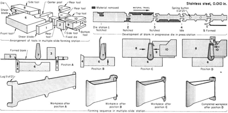
Fig. 14 Operations in the forming of a wristband link in a multiple-slide machine.
The blank for the link was made in a five-station progressive die mounted in the press station of the machine. As shown in
the upper right corner of Fig. 14, the strip was notched in stations 1, 2, and 3 by four small heeled punches. For support
against side thrust, the heels entered the die before engaging the stock. An air blast entering through holes in the punches
removed the scrap in order to protect the die and the feed mechanisms. In the fifth die station, two lugs on the blank were
bent 60°. Spring-actuated lifters stripped the blank from the bending section of the die after the lugs were bent. The
workpieces were held together by a narrow strip of stock that was left to index the workpiece through the stations of the
progressive die.
The blank was then fed to the forming station so that it was edge-up between the center post (7) and the front tool (6), as
shown in position A in Fig. 14. As the blank entered the forming station, the center post moved upward into the forming
position. The shear blade (1) then moved forward against the fixed die (2) to trim off the joining strip. The shear blade (1)
also bent the end of the blank against the auxiliary rear tool (3), which then retracted. The other end of the blank was cut
off by the shear blade (4) against the die (5).
After the blank was cut off by the shear blade (4), the front tool (6) bent the workpiece around the center post (7), as
shown in position B in Fig. 14.
In position C, the workpiece was formed on the center post by the side tools (8 and 9) while still being held by the front
tool (6). The front tool was wide enough to form the full width of the workpiece, including the lugs, but the side tools (8
and 9) were narrower, leaving exposed the top and bottom lugs that had been formed in the last press-die station.
In position D, the front and side tools (6, 8, and 9) held the part against the center post (7), while the rear tools (11)
flattened the top and bottom lugs against the center post. The center post was then lowered from the workpiece. The side
tool (9), which was spring loaded, slid between the top and bottom tools (10), permitting them to advance to form the top
and bottom lugs into a U-shape. The side tool (9) held the workpiece against the front and side tools (6 and 8), while the
top tools (10) tucked in the lugs.
With all the other tools holding the closed position against the workpiece, the rear tools (11) moved slightly to press the
lugs closed against the top tools (10). As the tools opened, the completed link was then ejected by an air jet.

Forming of Stainless Steel
Revised by Joseph A. Douthett, Armco Inc.
Deep Drawing
The percentages of reduction obtainable in deep drawing range from 40 to 60% for the chromium-nickel (austenitic)
stainless steels of best drawability and from 40 to 55% for the straight-chromium (ferritic) grades (percentage of reduction
= [(D - d)/D] × 100, where D is the diameter of the blank and d is the inside diameter of the drawn piece). The amount of
reduction obtainable varies greatly with the radius of the die and to a lesser extent with the radius of the punch nose. As
the die radius decreases, the drawability decreases, as shown in Table 6 for austenitic stainless steel. Typically used punch
and die radii are five to ten times metal thickness. With the ferritic grades, the drawability and ductility usually decrease
with increasing chromium content. To offset this, steels with high chromium content are often warmed moderately before
drawing.
Table 6 Effect of die radius on percentage of reduction obtainable in the deep drawing of aust
enitic
stainless steel
Percentage of reduction = [(D - d)/D] × 100, where D is the diameter of blank, and d is the inside diameter of the drawn piece
Die radius
(a)
Reduction
in drawing, %
15t
50-60
10t
40-50
5t
30-40
2t 0-10
(a)
t, stock thickness
Presses used for the deep drawing of stainless steel differ only in power and rigidity from those used for low-carbon steel.
Because of the higher work-hardening rate of stainless steel and its inherent higher strength, presses used for the deep
drawing of stainless steel often need 100% more ram force and the necessary frame stiffness to support this greater force.
Dies for drawing stainless steel must be able to withstand the high force and resist galling. For ordinary service, D2 tool
steel dies give a good combination of hardness and toughness. On long runs, carbide draw rings have exceptionally long
life. Where friction and galling are the principal problems, draw rings are sometimes made of high-strength aluminum
bronze. The following example describes an application in which the selection of tool material was critical in order to
avoid scoring of the workpiece and to obtain acceptable die life in drawing.
Example 12: Use of a Carbide Blank-and-Draw Ring.
An orifice cup, 25 mm (1 in.) in diameter by 11 mm (
7
16
in.) deep, was blanked and drawn in one operation. A 1.35 mm
(0.053 in.) diam orifice was pierced in the cup in a second operation. The specifications called for the sides of the cup to
be free of score marks from the die. The blank was 40.0 mm (1.575 in.) in diameter, cut from 0.97 mm (0.038 in.) thick
type 302 stainless steel strip 50 mm (2 in.) wide.
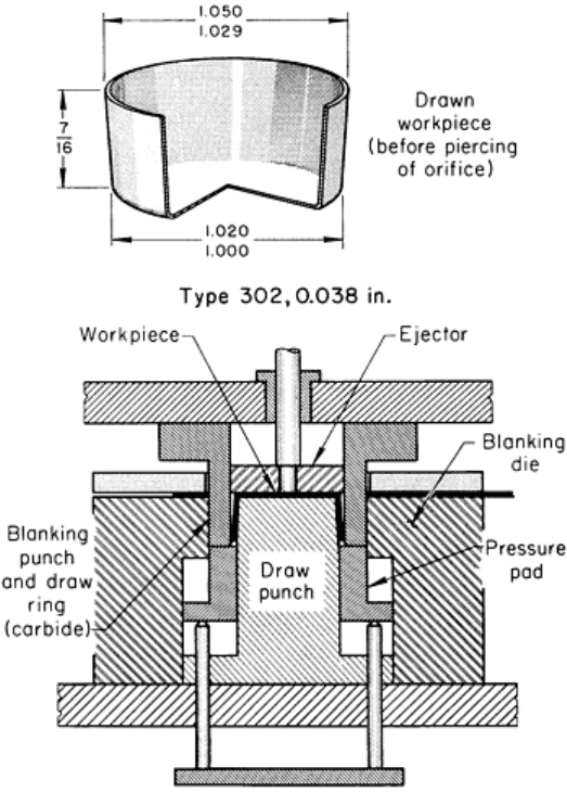
The blank-and-draw tooling shown in Fig. 15 was originally made of tool steel of a grade no longer used. It produced
fewer than 50 pieces without scoring the workpieces. The combination blanking punch and draw ring was chromium
plated in an attempt to increase its durability. Adhesion of the plating was not satisfactory; the chromium started to peel
after 180 pieces had been produced. A draw ring of graphitic tool steel was then tried, but this also scored the workpieces.
Fig. 15 Forming an orifice cup in a blank-and-
draw die with a carbide punch and draw ring. Orifice was pierced
in a second operation. Annual production was 60,000 pieces. Rate of blanking and drawing was 670 pieces per
hour. Rate of piercing was 153 pieces per hour. Dimensions given in inches.
Finally, a new draw ring was made of sintered carbide consisting of 81% tungsten carbide, 15% Co and 4% Ta--a
composition especially recommended for draw dies. The new ring, used with a chlorinated oil-base lubricant, withstood
the heat and pressure generated by the severe blank-and-draw operation and produced mar-free parts. Maintenance was
negligible, and after 3 years the carbide draw ring had produced 180,000 pieces, with little evidence of wear.
The blanking punch-to-die clearance was 0.05 mm (0.002 in.) per side. Drawing punch-to-die clearance was 0.851 mm
(0.335 in.) plus 3° taper per side on the draw punch. The punch nose radius was 0.38 mm (0.015 in.), and the draw radius
was 2.4 mm (0.093 in.).
Effect of Worn Draw Rings. The following example shows how the gradual wear of carbide draw rings in severe
drawing affected the outside diameter of drawn shells.
Example 13: Effect of Wear of a Carbide Draw Ring on the Diameter of a Drawn
Shell.
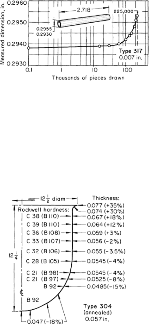
The carbide draw ring used in deep drawing a shell for pens and pencils made more than 225,000 pieces before it was
replaced. Measurements of the pieces were made at production intervals, as shown in Fig. 16.
Shortly after 225,000 pieces had been drawn, shells
began to be produced that would no longer enter the
"go" ring gage freely, because of wear on the draw ring.
The worn draw ring, which permitted excessive
springback, was replaced before the beginning of the
next production run.
The shell was drawn from a blank of type 317 stainless
steel 48.4 mm (1.906 in.) in diameter and 0.18 mm
(0.007 in.) thick to a finished depth of 69.0 mm (2.718
in.) using chromium-plated punches. The shell was made
in eight single-station dies, seven drawing and one end
forming, at a rate of 600 per hour. The punches had a
2.29 mm (0.090 in.) nose radius, and the draw dies had a
90° conical entrance angle with a 1.52 mm (0.060 in.)
radius blending the corners. A mixture of three parts
inhibited hydraulic oil and one part chlorinated oil was
used as lubricant.
Die clearance for heavy draws is 35 to 40% greater than the original metal thickness for austenitic alloys. For the
ferritic alloys, which thicken less, 10 to 15% is generally adequate.
Figure 17 shows a profile of an austenitic stainless steel drawn part that illustrates the thickening pattern observed in
drawing a cup from this material. If the process is one of stretching more than of drawing, the clearances do not have to
compensate for natural thickening.
Clearances of less than the metal thickness are generally not used
with stainless steel, because they result in ironing (squeezing of the
metal between the punch and die). The austenitic stainless steels
are not suited to ironing, because their high rate of work hardening
promotes scoring and rapid wear of the dies. In addition, any
substantial ironing in the drawing of austenitic stainless steels
greatly increases the likelihood of fracturing the workpiece.
The example below describes an application in which the work
metal was changed from galvanized carbon steel to a thinner
ferritic stainless steel without a revision of die clearance. The
resultant problems were solved by substituting an austenitic
stainless steel that was better suited to the original clearance even
though it had the same thickness as the ferritic steel.
Example 14: Matching Work Metal to Die
Clearance.
Using the tooling shown in Fig. 18, basins were made at the rate of
10,000 to 15,000 pieces per year from galvanized carbon steel,
1.27 mm (0.050 in.) thick. The press was an 8900 kN (1000 tonf)
hydraulic press with an air-over-oil pressure pad and a draw rate of
152 mm (6 in.) in 5 s. The punch, draw ring, and pressure pad for
the drawing die (Fig. 18a) were hardened cast iron. Carbide inserts
were used as cutting edges on the trimming punch and die (Fig.
18b). The locator on the trimming die was molded plastic, and the
die plate was cast iron. Both dies were used side-by-side in the press at the same time because it had enough capacity to
draw and trim in one stroke. Therefore, a finished piece was produced with each stroke of the press, using manual
transfer.
Fig. 16 Variation in diameter of a deep-drawn shell th
at
resulted from wear of the carbide draw ring used.
Dimensions given in inches.
Fig. 17
Profile of a shell drawn from an
austenitic stainless steel showing variations in
hardness and thickness produced by drawi
ng.
Dimensions given in inches.
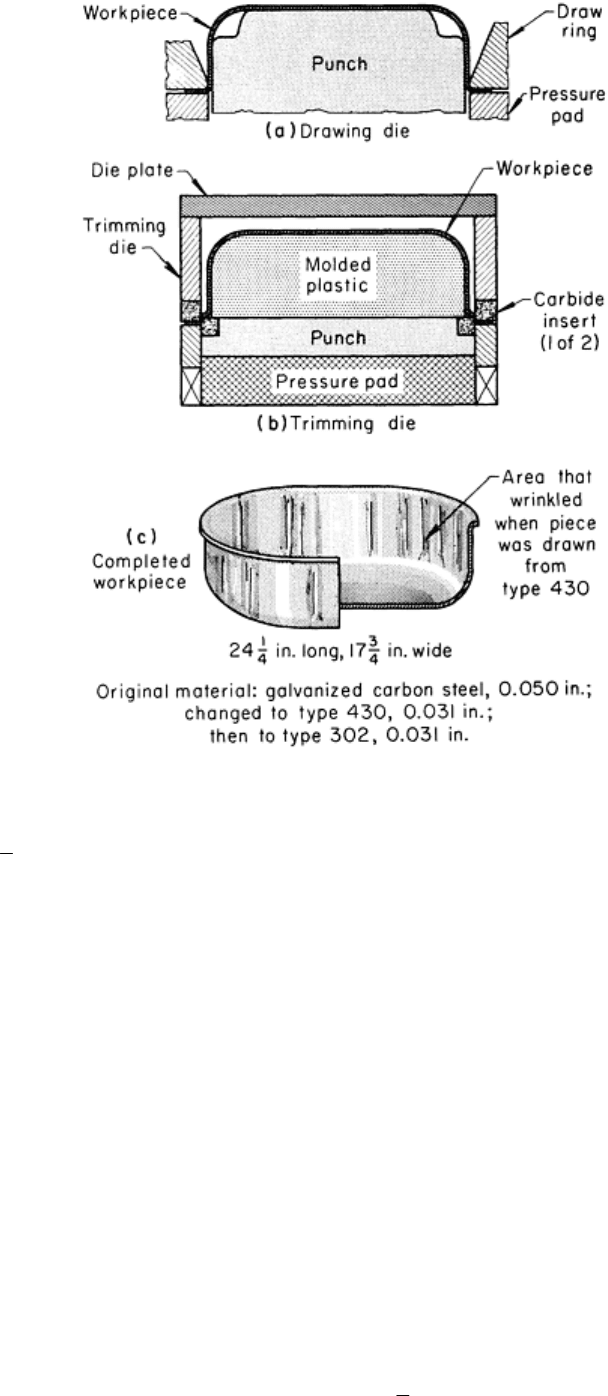
Fig. 18 Setups for drawing and trimming a basin. Die clearance (1.40
mm, or 0.055 in., per side) and drawing
radius (6.4 mm, or
1
4
in.) were not changed when 0.79 mm (0.031 in.) thick type 430 was substituted for 1.27
mm (0.050 in.) thick galvanized carbon steel as the work metal, and wrinkles resulted in drawing.
Dimensions
in figure given in inches.
To produce a more corrosion-resistant basin, type 430 stainless steel was substituted for the galvanized carbon steel. The
type 430 was only 0.79 mm (0.031 in.) thick in order to minimize the increase in material costs; however, the same
tooling was used because the relatively low annual quantity did not warrant the cost of retooling. Because the hold-down
forces were not suitable for the ferritic stainless steel, several hundred pieces out of the first run were fractured in
drawing.
When the hold-down pressure was adjusted to a level suitable for a ferritic stainless steel, contraction wrinkles formed
where the material entered the throat of the die (Fig. 18c) because the die clearance was too great. The corners of the
blank were cropped, the viscosity of the lubricant was changed, and the hold-down pressures were more closely adjusted
in an effort to control wrinkling.
The data given in Table 7 for noncylindrical draws provide an explanation for the difficulties encountered in changing the
work metal as well as guidance for the selection of a suitable stainless steel. According to these data, the thickness of type
430 stock that could best be formed by the die would be the same as that of the carbon steel previously formed. In
addition, if the stock thickness were reduced, an austenitic steel such as type 302 could be used. The die clearance was 1.4
mm (0.055 in.) per side, and the draw ring radius was 6.4 mm (
1
4
in.). Therefore, the die was suited for the 1.27 mm
(0.050 in.) thick carbon steel, but not for the 0.79 mm (0.031 in.) thick type 430. However, 0.79 mm (0.031 in.) thick type
302 would be closely matched to the die capacity.
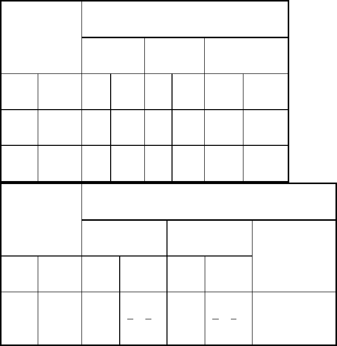
Table 7 Effect of die clearance and draw ring radius on noncylindrical draws of stainless steel
Die clearance per side
Stock thickness, t
Carbon steel
Type 430
Types 302 and 304
mm in. mm
in. mm
in. mm
in.
1.27 0.050 1.40
0.055
1.40
0.055
2.29
0.090
0.76 0.030 0.84
0.033
0.84
0.033
1.37 0.054
Draw ring radius
Stock thickness, t
Carbon steel Type 430
mm in. mm in. mm in.
Types 302 and 304
1.27 0.050 6.4-9.5
1
4
-
3
8
6.4-9.5
1
4
-
3
8
4t min
A change was made to type 302 stainless steel, 0.79 mm (0.031 in.) thick, with no further difficulty. A change to 1.27 mm
(0.050 in.) thick stock of type 430 might have been successful.
Speed of drawing has an important bearing on the success of the draw. A rate of 6 to 7.5 m (20 to 25 ft) per minute is
a good compromise between the rate of work hardening and the uniform distribution of stress. With proper forming
techniques, the rate of fracture at this speed is often less than 2%.
Lubricants. Ordinarily, both sides of the workpiece need to be lubricated for each draw. If too little lubricant is used,
tools may accumulate enough heat during a production run to cause the work metal to fracture because of galling. In tests
with a minimum of lubricant, failures occurred after 25 draws.
The chemical type and the viscosity of the lubricant are both important. Either chemical or mechanical EP activity (see
the article "Selection and Use of Lubricants in Forming of Sheet Metal" in this Volume) is needed for the severe deep
drawing of stainless steel.
Viscosity or pigment loading must not be too high or too low. Too thick a lubricant can cause wrinkling of compressed
metal; too thin, seizing or galling. The ability to remove a lubricant readily is also important. In general, the higher the
viscosity, the more difficult the lubricant is to apply and remove.
The same characteristics that make chlorinated oils and waxes useful for the press forming of stainless steel (see the
section "Press-Brake Forming" in this article) also make them useful for the deep drawing of these alloys. Table 2 lists
other lubricants used in the deep drawing of stainless steel. Pigmented pastes and dry films are also effective (and in some
cases superior) in deep drawing.

In Example 15, changing from a viscous mineral oil to a low-viscosity mineral oil blend of a chlorinated wax eliminated
wrinkling and galling. Sometimes, however, there is no substitute for the physical separation and equalization of pressure
provided by pigments, as in Example 16.
Example 15: Effect of Reducing Viscosity and Adding Chlorinated Wax to
Mineral Oil Lubricant in Deep Drawing.
A coffeepot was deep drawn from a type 302 stainless steel blank, 355 mm (14 in.) in diameter by 0.81 mm (0.032 in.)
thick, in two deep draws and one bulging operation. At first, the blanks were lubricated by brushing both sides with
mineral oil having a viscosity of 6000 SUS at 40 °C (100 °F). The workpiece wrinkled in the first draw, and it galled in
the second draw and in bulging.
The lubricant was replaced with a thinner mineral oil (viscosity: 500 SUS at 40 °C, or 100 °F) that was fortified with a
chlorinated wax. The lubricant was brushed on, as before. Not only did the use of the modified lubricant eliminate the
wrinkles in the first draw, but enough lubricant remained on the surface to prevent galling in the two other operations.
Even though a fluid of much lower viscosity was used, the tenacity imparted by the chlorinated wax permitted the
retention of sufficient lubricant for the subsequent bulging and deep-drawing operations.
Example 16: Pigmented Paste Versus Chlorinated Oil for Deep Drawing.
For easy cleaning in a vapor degreaser, highly fortified oils were specified for the deep drawing of a rectangular shell
from 0.89 mm (0.035 in.) thick type 304 stainless steel. Chlorinated and sulfochlorinated oils with viscosities of 4000 to
20,000 SUS at 40 °C (100 °F) failed to eliminate welding to the dies and splitting of the workpiece at the corners. The
shell, a well for a steam table, was deep drawn from a rectangular blank measuring 760 × 585 mm (30 × 23 in.) with
corners trimmed at 45°. The shell was drawn in one operation, and the flange was then trimmed. Interior dimensions of
the drawn shell were 510 × 305 × 150 mm (20 × 12 × 6 in.). Bottom corners had 16 mm (
5
8
in.) radii; vertical corners, 29
mm (1
1
8
in.) radii; and the flange, a 6.4 mm (
1
4
in.) radius. The shell had approximately 3° taper on each side. The
clearance between the punch and die was equal to the stock thickness.
The oil-type lubricant was replaced with a highly pigmented water-miscible fatty paste, diluted with two parts of water,
which was applied to both sides of each blank by rollers. This lubricant eliminated the welding and allowed enough metal
flow to prevent splitting. The drawn parts were cleaned with hot alkaline solution in a soak tank.
Lubricant Location. The location of the lubricant on the blank is also critical in the successful fabrication of a drawn
part. Because all draws are made up of a combination of stretching and deep drawing, the lubricant location often depends
on which type of forming is dominant. In a stretch condition, lubricant should especially be applied on the steel surface
contacting the punch so that friction is minimized and the steel slips over the punch surface during stretching and
thinning. Under deep-draw conditions, the steel surface contacting the die is definitely lubricated in order to allow ease of
movement into the die cavity. However, whether stretch or deep drawing dominates, some lubricant is necessary on both
steel surfaces to minimize the galling tendencies of stainless alloys.
Drawing Cylindrical Parts. When a part is made in several drawing operations, the amount of reduction in redrawing
is related to the condition of the metal in the first drawing operation (cupping). If the material is highly stressed because
of excessive blankholder pressure or because of small die radius, very little reduction can be made in the second
operation.
General practice on the more formable grades of austenitic stainless steel is to allow 40 to 45% reduction in the first
operation, followed by a maximum of 30% in the second operation, if the workpiece is not annealed between draws. With
an anneal, the second reduction is usually 30 to 40%. On some parts, it may be preferable to spread the reduction over
four draws before annealing--for example, successive reductions of 35, 30, 20, and 10%.
There is usually a decrease in drawability upon redrawing, and the greatest total reduction in a two-draw operation is most
often produced by having the first-stage reduction as large as possible. During redrawing, it is advisable to use a tapered
or rounded-end internal blankholder or sleeve to allow easy flow of metal into the die, as indicated in the article "Deep

Drawing" in this Volume. An internal blankholder with small-radius 90° corners causes the metal to be bent severely
through two 90° bends before flowing into the die.
Optimal drawability is available at ram speeds of not more than 6 to 9 m (20 to 30 ft) per minute. Because of the strain-
rate sensitivity of most stainless steels, work hardening of these alloys is minimized by slow forming.
The following example describes an application in which small shells were deep drawn in several steps to reduce the
amount of work done in a single operation. Because production quantities were small, individual dies were more
economical than a transfer die.
Example 17: Seven-Step Deep Drawing of a Fountain-Pen Cap.
Fountain-pen caps of various closely related designs were made on the same production line by one blanking and cupping
operation and six redraws. A flat blank of type 302 stainless steel having a hardness of 83 to 88 HR15-T was used. The
first five draws were usually the same for any of the caps made on the line; therefore, to set up for a different size of cap,
only the compound blank-and-cup die and the last die (or, for some caps, the last two dies) needed to be changed. As a
result, the changeover time was only about 45 min.
In the first operation, which was done in a 160 kN (18 tonf) mechanical press, a compound blank-and-cup die equipped
with a rubber die cushion was used to cut circular blanks from 0.267 to 0.279 mm (0.0105 to 0.0110 in.) thick strip and to
draw them into a cup. To make a typical cap 90 mm (3
1
2
in.) long by 8.55 to 8.57 mm (0.3365 to 0.3375 in.) in outside
diameter, a blank 55.9 mm (2.200 in.) in diameter was cut from stock 57 mm (2
1
4
in.) wide and was drawn into a cup 19
mm (
3
4
in.) deep by 31.8 mm (1.250 in.) in diameter--a 43% reduction in diameter. Reductions in the subsequent redraws
were 27, 22, 18, 18, 16, and 15%, respectively. All except the last redraw were done in 35 kN (4 tonf) hydraulic presses
with 152 mm (6 in.) strokes. The final redraw was made in a 55 kN (6 tonf) hydraulic press with a 305 mm (12 in.) stroke.
The draw dies were carbide inserts 13 to 16 mm (
1
2
to
5
8
in.) thick. The die openings had a 4.8 mm (
3
16
in.) radius
blending with a 1.6 mm (
1
16
in.) wide land. There was a 2° relief per side below the land. The high-speed steel punches
had a 2.4 mm (
3
32
in.) nose radius and were chromium plated for smoothness and wear characteristics. The workpiece
was pushed through the die and stripped from the punch by a split stripper plate under the draw die. The strippers were
closed by cam action from the press stripper rod.
Because production quantities of any one part were small, this technique was preferable to making a transfer die for each
of the several caps produced on this line. Operations were set up in machines in the line as they were needed and as the
machines became available.
The final draw, which was the deepest, governed the final production rate of 575 pieces per hour. However, when there
was a backlog of pieces, this operation was set up on two machines at the same time.
The blank-and-cup die made about 45,000 pieces before resharpening. The draw rings were used for 150,000 to 200,000
pieces before wear was too great. Dies in the first few draws were allowed to wear over a fairly wide range. As the die
opening increased, clearance was maintained by increasing the thickness of the chromium plating on the punch. When the
die openings were 0.10 to 0.13 mm (0.004 to 0.005 in.) oversize, the dies were replaced, and punches were returned to the
original size by stripping, polishing, and replating.
The lubricant was a mixture of one part sulfur-free chlorinated oil with three parts inhibited hydraulic oil having a
viscosity of 250 SUS at 40 °C (100 °F). This lubricant was furnished to all presses through a central pumping system.
Critical tolerances on these fountain-pen caps were ±0.02 mm (±0.001 in.) on outside diameter and ±0.01 mm (±0.0005
in.) on inside diameter. Holding the clearance between the draw die and punch to 10% greater than stock thickness helped
to maintain these tolerances.
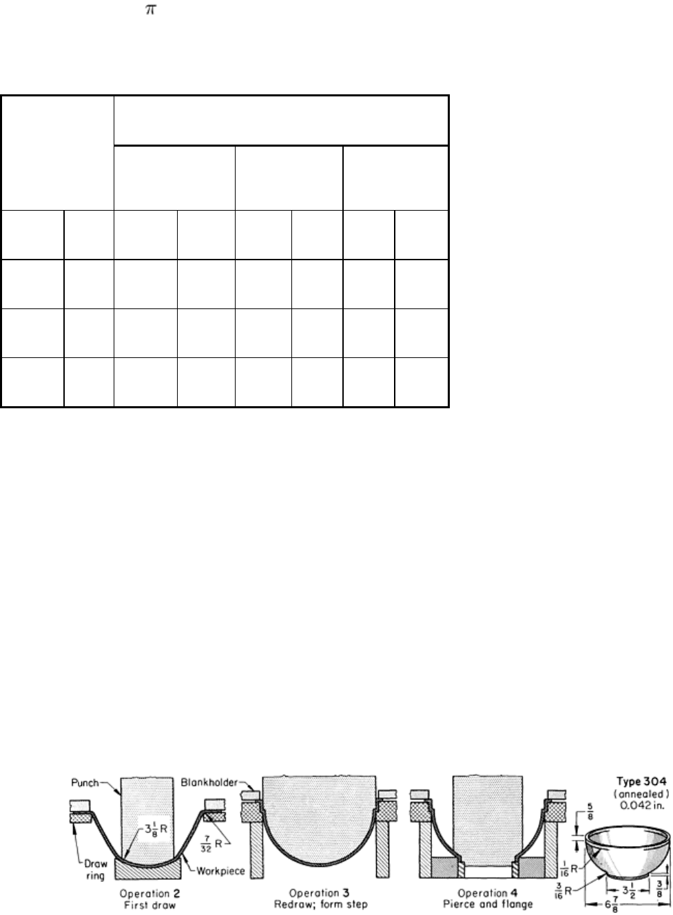
Steel Drawing Forces. Estimates of the maximum drawing forces necessary to form cups from an austenitic stainless
steel, a ferritic stainless steel, and low-carbon steel are compared in Table 8. These drawing forces, in tons of force, are
based on the formula S Dt, where S is the tensile strength of the metal in tons of force per square inch, D is the cup
diameter in inches, and t is the metal thickness in inches.
Table 8 Force required for drawing two stainless steels and low-
carbon steel of 1.27 mm (0.050 in.)
thickness to various diameters
Approximate drawing force required
Diameter of piece
Austenitic stainless
steel, type 18-8
Ferritic stainless
steel, 17% Cr
Low-carbon steel
mm in. kN tonf kN tonf kN
tonf
125 5 350 39 180 20 160
18
255 10 700 78 520 59 350
39
510 20 1400 157 1040 117 700 78
Blankholding pressures for the austenitic alloys must be much higher than those for the ferritic types or low-carbon steels.
For austenitic alloys, the pressure, P, on the metal under the blankholder is usually about 6.9 MPa (1.0 ksi); for the ferritic
alloys, 1.4 to 3.4 MPa (0.2 to 0.5 ksi). Thinner material and larger flange areas generally require greater pressure.
Drawing Hemispherical Parts. The drawing of hemispherical, or dome-shaped, parts demands special attention to
blankholder pressure to prevent wrinkling because so much of the metal surface is not in contact with any die surface for
most of the draw. Only the very tip of the punch is in contact with the work at the start of the stroke, and the surface
between the tip and the blankholder draws or stretches free until the punch descends far enough to contact it. An
undersize punch can sometimes be used to draw or stretch the blank into a preform before the dome-shaped punch makes
the final draw, as in the following example.
Example 18: Two-Stage Drawing of a Stepped-Diameter Hemisphere.
One of the critical points in the production of the vacuum-bottle top shown in Fig. 19 was the forming of the shoulder at
the large end of the dome-shaped top. The stepped inside diameter of this shoulder had to be an exact fit with the body of
the vacuum-bottle jacket. The pierced hole at the small end also had to be accurately formed to conform to the mouth of
the inner container.
Fig. 19 Production of a stepped-
diameter flanged hemisphere, in which a narrow punch was used in predrawing
