Altan T. Metal Forming Handbook
Подождите немного. Документ загружается.

ver’s cab. Both operations are generally executed in a single line using
two die sets.
When manufacturing side members, two different methods are used
in conjunction with different types of production lines. These are dis-
tinguished from each other already in the blank feed stage.
Side members with a length of up to 7 m are generally manufactured
from plates, which have a maximum thickness of 4mm. The plates are
fed into the press on an intermittent basis transversely to the longitu-
dinal axis of the press. With each stroke the blanking die in the press
punches a contoured blank from the plate. The blank is then bent in
the next station to become a side member.
To produce side members with a length ranging from 4 to 13m,
blankswith a thickness of 5 to 10 mm are available. The blanks are
generally cross-cut directly off the coil to the contoured blank width
(cf.Sect.4.6.1) in order to ensure optimum material utilization. The
camber shaped blanks produced using this method have to be correct-
ed in a separate unit by straightening. The straightened blanks are fed
individually into the longitudinal axis of the press and processed to cre-
211
Sheet metal forming lines
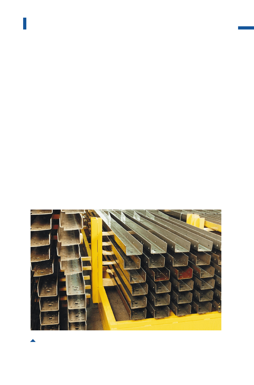
Fig. 4.4.12Side members used in truck production
Metal Forming Handbook / Schuler (c) Springer-Verlag Berlin Heidelberg 1998

ate a contoured blank. This is done either by an all round blanking
stroke or by local edge blanking – generally at both ends of the side
member.
The advantage of processing sheet plates is that the blanks do not
assume a camber shape due to the all round blanking cut used in their
manufacture. Thus, the straightening process can be omitted. However,
in this case a lower degree of material utilization is achieved. In the case
of complex side member geometries, involving different flange and
web heights, however, it is possible to save on material input by nesting
the contoured blanks (cf. Fig.4.5.2to 4.5.5).The blanking cut leaves
behind scrap webs which are broken down into scrap segments.
Production line concepts
There are two basic line types used to produce side members. These dif-
fer in principle, based on the infeed and outfeed direction of the sheet
metal: Whereas sheet plates below 7m in length can still be fed into the
press through the press uprights transversely to the longitudinal press
axis, longer untreated blanks have to be fed parallel to the longitudinal
press axis.
In lines wheretransport takes place parallel to the longitudinal press axis,
the blanks are fed by means of an infeed conveyor belt inside the press
uprights (Fig.4.4.13). Cross-feed units simultaneously feed the uncut
blank into the die and the previously contoured blank out of the die
onto the reverse outfeed conveyor. Transport systems making use of
magnets are used to stack the contoured blanks emerging from the out-
feed conveyor. Integrated in the line is also a blank turning station. The
lines are designed in such a way that both, contoured blanks punched
from uncut blanks and side members formed from contoured blanks,
can be manufactured.
Important accessories for use with fully automatic lines include a
blank lubricating or spraying device at the press infeed, a hole pattern
camera to detect punch breakage and a device for edge milling. Fully
automatic lines achieve cycle times of 3 strokes per minute. Taking into
account the need for two passes and without considering the set-up
time of around 15 min required for the change from blanking to bend-
ing, this results in an average line output of some 1.5 side members per
minute. Die changeover also takes place in the longitudinal axis of the
press.
212
Sheet metal forming and blanking
Metal Forming Handbook / Schuler (c) Springer-Verlag Berlin Heidelberg 1998
In the case of presses with material transport transversely to the longitu-
dinal press axis, the sheet plates are guided between the press uprights
by means of a chain conveyor and a gripper feed device in synchro-
nization with the press cycle. After each stroke, the remaining plate
pushes the newly punched contoured blank onto the reverse outfeed
conveyor belt. When an operation has been completed, the waste strip
of the old plate must be disposed of together with the blanking waste
from the new plate.
The equipment used for destacking the bales of plates or contoured
blanks and the other elements of the line are the same as those used in
lines transporting the material in the direction of the longitudinal press
axis.
213
Sheet metal forming lines
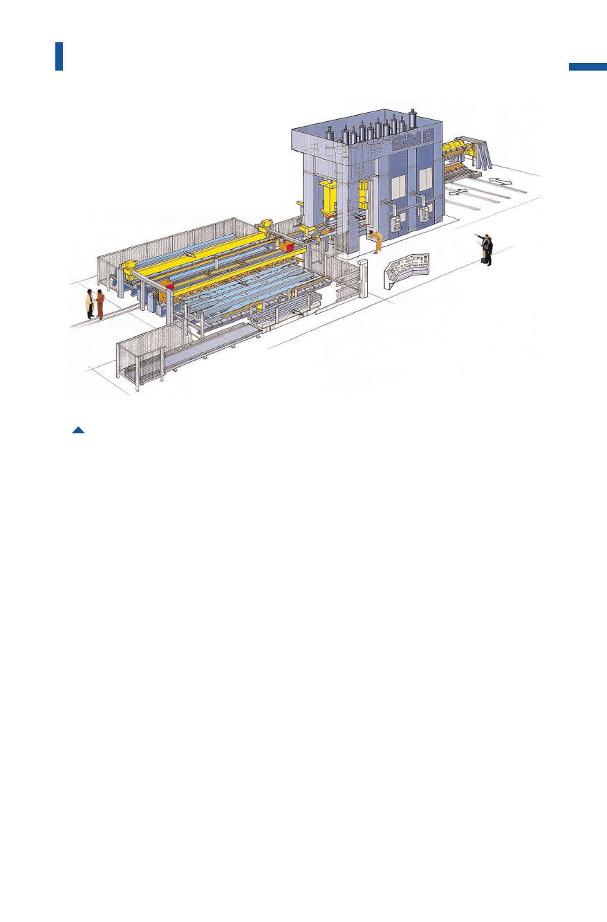
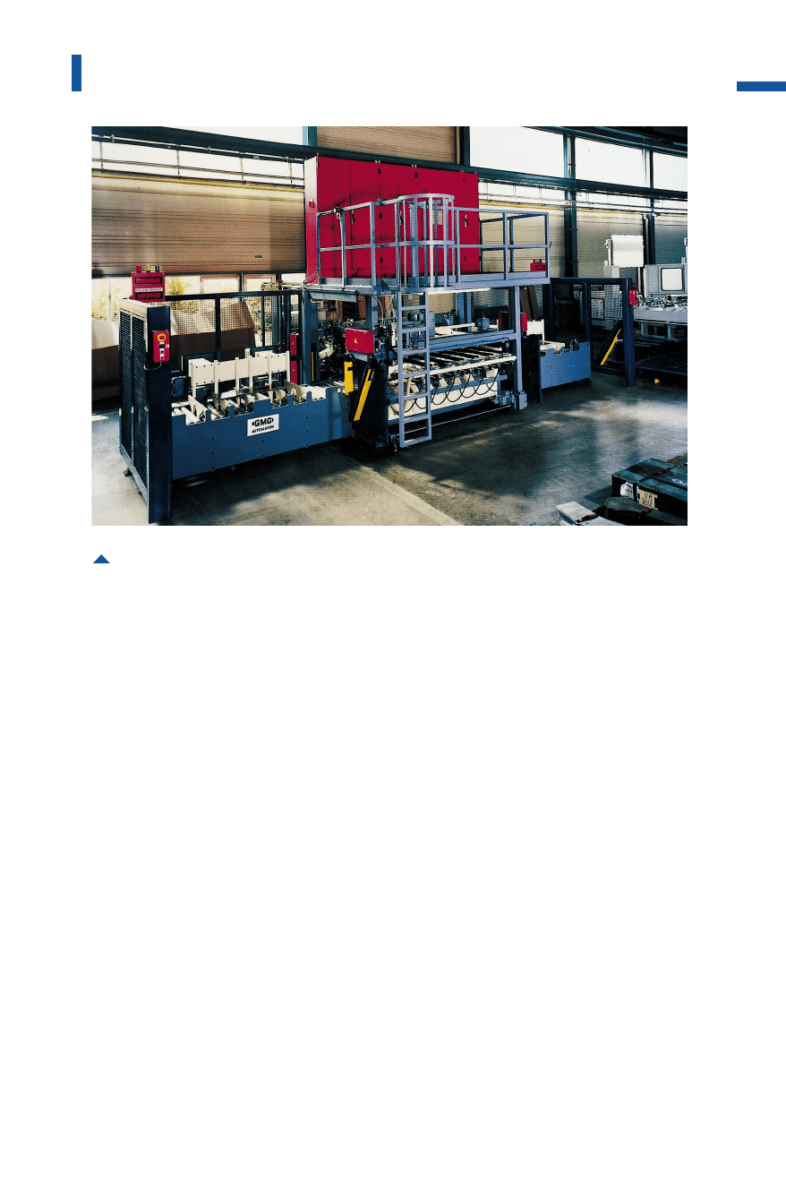
Fig. 4.4.13 Layout of a line for the manufacture of truck side members
(F
N
= 50,000 kN, blanking shock damping and stroke limitation, 11 bed cushions,
25 slide ejectors, maximum off-center load: 25,000 kNm with electronic control
of parallelity)
Metal Forming Handbook / Schuler (c) Springer-Verlag Berlin Heidelberg 1998

Die concept
The blanking and bending die each comprise a basic die equipped with
trimming and piercing modules in accordance with the various side
member lengths. Side members are structured in such a way that cer-
tain groups of holes, for example those used to fasten the front and rear
suspension mounting, are identical and only change relative to the
wheel base. In the area of the driver’s cab at the front end of the side
member, the contour and hole patterns are identical. The modules are
accordingly adjusted and positioned according to the requirements of
each individual side member type:
– front module for the area of the driver’s cab,
– main module, for example for the rear axle area,
– intermediate module to bridge different side member lengths and
– the end module.
If at all possible, right and left-hand side members should have the same
hole pattern. Only then it is possible to minimize the effort required for
drawing and mounting piercing hole punches when changing set-up
from right-hand to left-hand side members. The shearing edges required
for blanking the side member contour do not have to be reset, as for
example the left-hand contoured blank is produced from the right-hand
contoured blank by simply rotating it in the turning station. However,
for the bending process, bending dies, forming edges and ejector beams
in the asymmetrical areas must be changed for a new set-up.
As the position of the front module does not change, if the length of
the side members decreases, the position of the workpieces in the
blanking and bending dies becomes increasingly off-center. If a single-
sided coping cut is to be carried out at the same time, e.g. for example
when trimming the front, an additional off-center load is applied. The
off-center forces must be accounted for, either by a balancing module or
by providing a suitable press concept. Otherwise an unacceptable
amount of slide tilting action will occur.
To reduce the blanking force, the edges of the blanking die and
punch are configured in a saw-tooth arrangement and the piercing hole
punches are staggered on several blanking levels. The aim is to achieve
uniform loading over the entire length of the workpiece at every blank-
ing plane.
214
Sheet metal forming and blanking
Metal Forming Handbook / Schuler (c) Springer-Verlag Berlin Heidelberg 1998

During the bending process, the web surface of the side member is
supported above the bed cushion by means of a support beam. By vary-
ing the bed cushion pressure levels, it is possible to influence the flat-
ness of the web surface, and in particular the rectangularity of the ribs.
A stripping device in the die ensures controlled stripping of the angled
side members from the bending punch. Parallel ejection is achieved
using the support beams.
Segmented bed cushion
As a result of the variable side member length, the cushions at the end
zones of the side members are only partially in use. A tilting moment
occurs here which must be balanced by means of stable gibs.
If all bed cushions are activated at the same time during the upstroke
of the slide for ejection, the cushions which have the smallest load reach
the top dead center first. However, the side members must be ejected in
parallel formation in order to avoid damage. There are two alternatives
here: to eject the side member while maintaining continuous contact
with the top die during the upstroke of the slide, or to control the syn-
chronous ejection speed of all the cushions. If side members are formed
with right-angled bends, different cushion strokes are required.
Control of parallelity and cylinder deactivation
The pistons of the cylinders that control parallelity are located at the
outside of the slide. During the working stroke, they operate against the
mean pressure of the servo valves (cf. Fig. 3.3.5). The off-center loading
of the dies generates a tilting moment on the slide. In the event of a
deviation from parallelity, the pressure is increased in the control cylin-
der that is on the loading side while pressure on the opposite side is
reduced. A supporting moment occurs which acts opposite to the tilt-
ing moment. In the case of side member tools, the off-center loading of
the slide can be large due to the arrangement of the individual mod-
ules. In some cases, tilting of the slide can no longer be prevented by
control of parallelity at a reasonable cost. In such cases, the control of
parallelism is supported by the selective deactivation of individual slide
cylinders (Fig. 4.4.14). As a result, the center of application of the press
force shifts in the direction of the forces generated in the dies. The larg-
er lever arms of the parallelism control force help to increase the
moment acting opposite to the off-center loading. However, deactiva-
tion of individual cylinders reduces the maximum available die force.
215
Sheet metal forming lines
Metal Forming Handbook / Schuler (c) Springer-Verlag Berlin Heidelberg 1998
216
Sheet metal forming and blanking
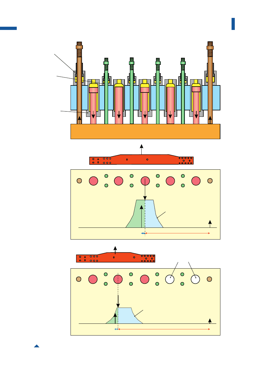
Fig. 4.4.14 Tilt and parallelity control moments in a press for forming side members
a
FF
FF
F
b
b a
slide cylinder
parallelity
control
cylinder
blanking
shock
damping
center of loading
center of loading
controllable
moment
controllable
moment
F
N
= 5 x F – F
PR1
– F
PR2
F
PR1
F
PR2
long side members
short side members
deactivated cylinders
F
N
F
U
F
PR2
3/5 F
N
F
U
F
PR2
Metal Forming Handbook / Schuler (c) Springer-Verlag Berlin Heidelberg 1998

4.4.4Destackers and blank turnover stations
Destackers
Destackers separate the blanks and feed them into the press in syn-
chronization with the press cycle. Where low stroking rates are
involved, the destacking and feeding operation is performed by feeders.
In the case of higher stroking rates, after destacking the blank is trans-
ferred onto magnetic belts which transport them into the centering sta-
tion, for example the pick up position of the press transfer.
Destackers with feeder and suction cup tooling
In the case of press lines (cf. Sect. 4.4.5) with a stroking rate of about 10
to 12 parts per minute and where suitable blank shapes are being
processed, feeder systems are used. In case of a die change, the entire
tooling is replaced together with the attached suction cups. During
destacking, the tooling suction cups pick up the top blank from a stack.
The operation is supported by fanning magnets whose magnetic field
fans the top-most blanks in order to prevent the blanks from sticking to
each other. The magnets can be positioned manually or automatically
near the stack. Both permanent fanning magnets and electrically pul-
sating magnets are used.
When processing non-magnetic materials, e.g. blanks from alumini-
um or stainless steel, only suction cups can be used. In this case, com-
pressed air is blown in from the side of the stack to enhance the sepa-
ration of the individual blanks.
Destackers with magnetic belts
This design is equipped with one or two cylinder-actuated destacking
units provided with vacuum cups or magnets (Fig.4.4.15). These are
lowered between the magnet belts on the top-most blank of the respec-
tive stack, and then raise and transfer the suspended blank to the mag-
netic belt conveyor. Here, too, fanning magnets are used to support the
removal of individual blanks. Using these systems, up to 25 relatively
small and up to 15 larger parts per minute can be fed into the press.
To ensure that the press is able to operate continuously when chang-
ing from one stack to the next, either two destacking stations or systems
with a reserve magazine are used. In the case of dual stacking feeders,
switchover from the finished to the new stack takes place automatically.
217
Sheet metal forming lines
Metal Forming Handbook / Schuler (c) Springer-Verlag Berlin Heidelberg 1998
Another possibility is to work with a reserve magazine. Here, the
remainder of the stack is supported and destacked off the reserve forks
while a new stack is added to it from underneath. Double blanks are
detected electronically and automatically separated out of the system
without bringing the entire line to a standstill.
In the case of non-magnetic materials, an integrated feeder with suc-
tion cups is used. Here, after destacking, the top-most blank is positioned
from above onto a conveyor belt. A lower cycle rate is expected when
using this type of handling system.
Another configuration used to transport medium-sized parts
involves the use of magnetic belts mounted on a lifting bridge, which
are lowered onto the stack of blanks. Thus, the top-most blank of the
stack is picked up. This type of system is driven by means of a crank
mechanism (Fig. 4.4.16).The maximum achievable cycle rate with this
method is about 16 parts per minute.
Prior to the forming operation, frequently the blanks must be
washed, lubricated, centered and oriented. These operations are inde-
pendent of the selected destacking method.
218
Sheet metal forming and blanking
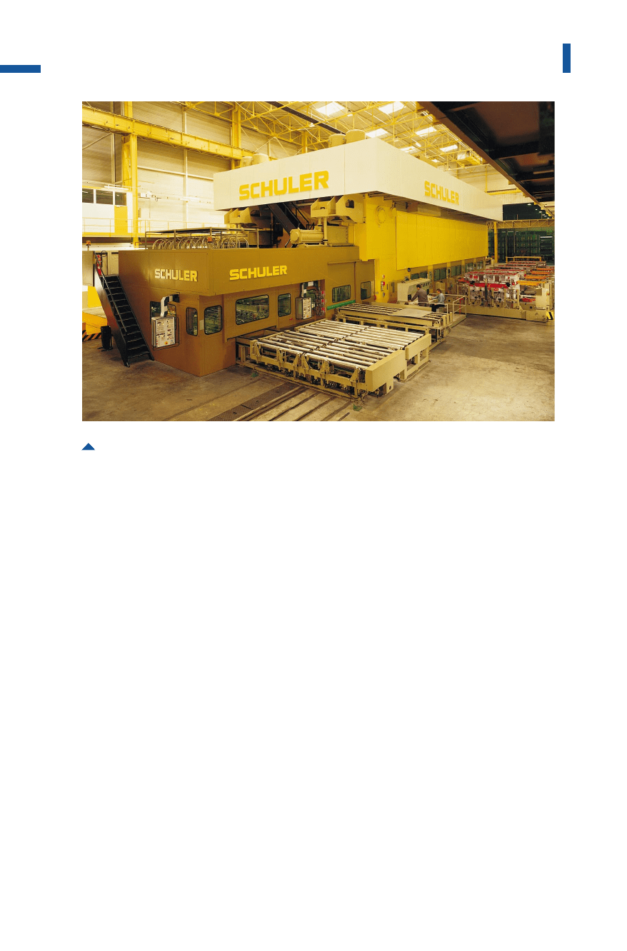
Fig. 4.4.15 Destacker of a large-panel transfer press for maximum blank dimensions of
3,800 31,800mm with a destacking bridge
Metal Forming Handbook / Schuler (c) Springer-Verlag Berlin Heidelberg 1998
Washing
To ensure the maximum possible part quality, the blanks – particularly
those used to produce visible parts such as doors and roofs etc. – are
washed and cleaned prior to forming. The washing/cleaning process is
performed using cleaning emulsions or oils in conjunction with clean-
ing brushes. The blanks are fed towards the washing machine through a
conveyor belt (Fig.4.4.22). The blank is mechanically washed in the
washing/cleaning machine by a pair of roller brushes. During this
process, the washing medium is continuously applied to the blank by
means of nozzles. Downstream from the pair of roller brushes is a pair of
squeezing rollers made of non-woven fabric. These reduce the cleaning
medium uniformly and assure that there is only a minimal residue. The
high throughfeed velocity based on the cycle rate is up to 150 m/min.
For less complex parts, subsequent lubrication can be eliminated if the
residue of the washing emulsion is sufficient for drawing, and the medi-
um used is suitable for this purpose.
219
Sheet metal forming lines
Fig. 4.4.16 Destacker with magnetic belt for maximum blank dimensions of 2,100 3750mm,
suitable for coated and non-coated blanks
Metal Forming Handbook / Schuler (c) Springer-Verlag Berlin Heidelberg 1998

Oiling/greasing
For selective lubrication of blanks, oil spraying and greasing devices are
integrated into the destacker. These can be used to apply the lubricant
partially on the upper and/or lower side of the blank. Modern oiling
devices are computer controlled and capable of partial greasing or oiling
of approx.200 mm length at throughfeed velocity of up to 150 m/min.
Centering/orientation
Before the blank can be automatically transported into the die, it must
be aligned or centered in line with the required position. Inaccuracies
may occur when positioning a blank. These may be due to the location
on the stack or transport and they are corrected by means of end stops
or lateral pushers. In order to obtain a high degree of flexibility con-
cerning the dimensions and geometry of the blanks, all the positioning
devices can be programmed and power adjusted. As a result, the set-up
times are reduced.
Turnover devices for blank stacks
Blanks intended for further processing in forming lines are parted from
the coil stock on blanking lines (cf. Sect.4.6.2) and layered to blank
stacks. In order to save tool costs, where symmetrical parts are involved,
only a single blanking die is produced. Thus, it is possible, for instance,
to use the blanks for the left-hand fender also for the right-hand side by
simply turning over the stack. A distinction is made between the fol-
lowing blank stack turnover concepts:
– Friction-locked stack turning device: The stack is pressed with suffi-
cient force so that friction holds the blanks together and then it is
turned over.
– Positive-locked stack turning device: When turning in a drum or fork
turning device, the stacks are mechanically supported.
Drum turning device: for blanks with complex geometries
Many blanks with irregular geometry, for example trapezoidal parts,
may slip out when the stack is being turned over. Therefore, the stack
must be supported on two sides by means of end stops. In addition,
turning devices are often required to occupy only a minimal space and
a single location to accommodate stacks both before and after turning.
220
Sheet metal forming and blanking
Metal Forming Handbook / Schuler (c) Springer-Verlag Berlin Heidelberg 1998