Altan T. Metal Forming Handbook
Подождите немного. Документ загружается.

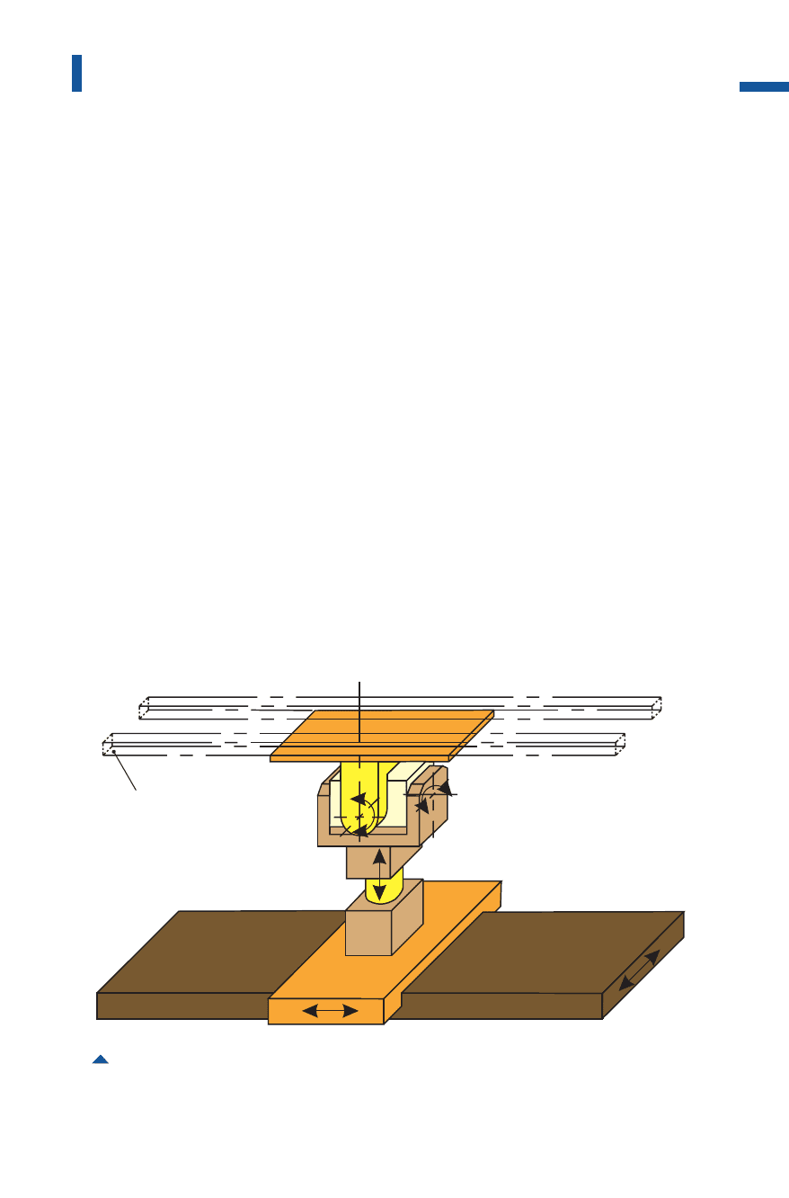
Draw cushion
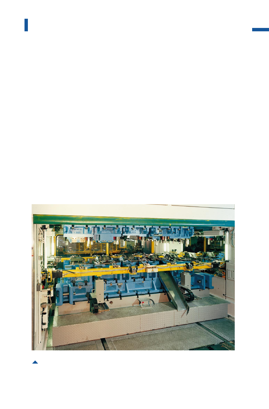
When producing car body parts on large-panel transfer presses, the blank
holder function must be performed by the draw cushion in the press bed
in order to permit the part to be further processed in the same position
(cf.Fig.3.1.11).Provided the geometry of the drawn part is suitable and
with adequate pre-acceleration of the draw cushion, good results can
be obtained using pneumatic draw cushions. However, the blank holder
force control is even more favorable when using microprocessor-con-
trolled hydraulic draw cushions (Fig.4.4.33and cf. Fig. 3.1.12). Even with
large drawing depths up to 250 mm, the use of this type of draw cushion
produces workpiece quality comparable to that achieved on double-
action presses. However, this system necessitates adjusting the die design
to the press (cf. Fig. 4.1.16)and transfer system, so that marginally higher
die costs must be taken into account. Retrofitting of existing die sets for
use in this type of large-panel transfer press must be reviewed individu-
ally in each case as regards costs and feasibility. A particularly econom-
241
Sheet metal forming lines
Fig. 4.4.32 Electrical transfer in a large-panel tri-axis transfer press
Metal Forming Handbook / Schuler (c) Springer-Verlag Berlin Heidelberg 1998
ical solution is to integrate a large-panel transfer press into the produc-
tion process when a model change is made and when new die sets have
to be manufactured.
Die change
In large-panel transfer presses, dies are also exchanged using moving bol-
sters which move automatically in and out on the left and right of the
press, in some cases simultaneously (cf. Fig.3.4.4).The die change area is
safeguarded by light barriers and partially monitored by video cameras.
The die changeover sequence is depicted in a die change diagram.
Initially, the part-specific contoured nests of the intermediate stations
are automatically transferred to the moving bolster. The part of the
gripper rails between the uprights to which the part-specific grippers
are attached, must be exchanged as part of the die change process.
242
Sheet metal forming and blanking
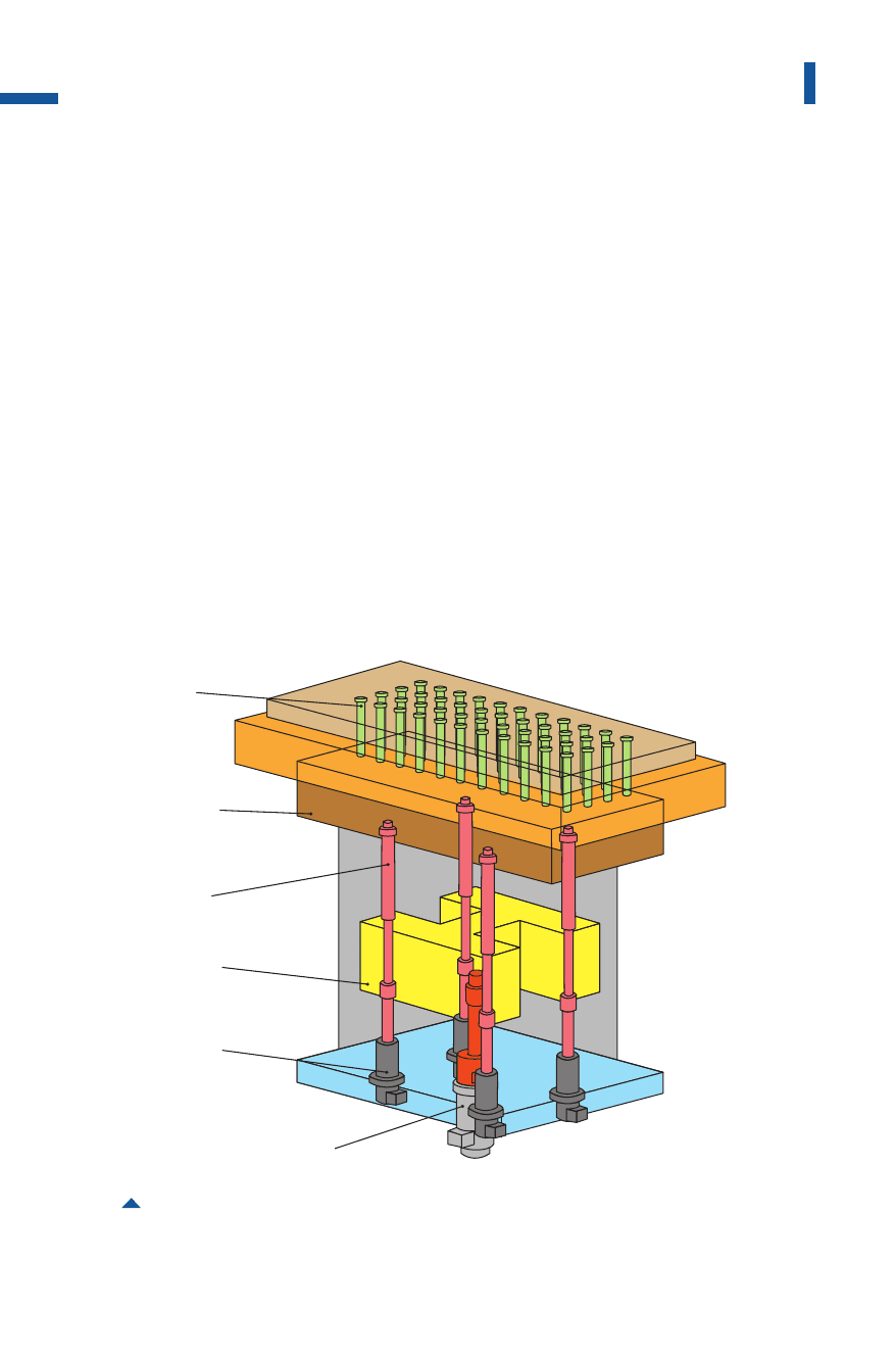
Fig. 4.4.33 Hydraulic four-point draw cushion with pressure pins
displacement
cylinders
pressure
column
pressure
pins
liftingcylinder
liftingbridge
diecushion
box
Metal Forming Handbook / Schuler (c) Springer-Verlag Berlin Heidelberg 1998

These components are separated from the part of the rail which
remains in the press by means of an automatic coupling device, and
deposited on the moving bolster.
After releasing the power connections, the moving bolster with the
die and part-specific accessories travels to one side out of the press,
while the sliding bolster with the next die enters from the other side
(Fig.4.4.27). After automatic coupling of the gripper rails and power
connections, the die data such as pressure levels and positions are
accessed from the data memory and automatically set. When the mov-
ing bolster with a new die set is set up outside the press, all the part-spe-
cific devices such as grippers and contoured nests are exchanged and
prepared for the next production process.
A characteristic feature of large-panel transfer presses is their high
productivity with an outstanding degree of flexibility made possible by
short set-up times. The automatic die change process possible in large-
panel transfer presses can be completed in less than 5 min. Thus, a
major precondition is satisfied for the reduction of capital costs and of
the need for intermediate storage of finished parts between the stamp-
ing plant and the body assembly plant. This means that, depending on
batch size, it may be possible to perform several die changes per pro-
duction shift (cf. Sect. 4.9.2).
Depending on the press operating period, on a large-panel transfer
press between 5 and 30 different die sets are used with batch sizes of
3,000 to 10,000 panels. To ensure economic utilization of the press, parts
with nearly identical form and size and a similar degree of forming com-
plexity should be grouped to create families of parts (cf. Fig. 4.9.2and
4.9.3).
4.4.8Crossbar transfer presses
Where large panels from around 2.5 31.5 m in size are processed, the
low inherent stability of the parts during transportation calls for special
measures. Conventional gripper rails which only grip or hold the parts
around their outer periphery (Fig.4.4.29)are not suitable. Particularly
large unstable parts such as roofs, full body side panels or floor assem-
blies are accordingly produced using crossbar transfer presses. The
application of this type of press also covers the dual production of
243
Sheet metal forming lines
Metal Forming Handbook / Schuler (c) Springer-Verlag Berlin Heidelberg 1998

medium-sized parts, in which two parts are formed from one blank or
two adjacent blanks (Fig.4.4.34and cf. Fig.4.9.2). Double parts pro-
duced from a single blank are separated as required in a subsequent
operation. The production of double parts could refer to any suitable
parts, for example passenger car doors. This kind of production doubles
the output per press stroke and increases considerably the economy of
the system, compared to gripper rail transfer systems. Moreover, dual
production helps to better utilize the press load capacity when forming
a single large and unstable part does not fully require the available press
load.
Large-panel crossbar transfer presses can be structured in different
ways. Ideally, each die should be assigned to a separate slide to ensure
optimum peripheral conditions for the die and for the forming process.
The design is based on a modular structure comprising individual
machines in which all the drive systems are connected to the main
press drive system by means of central longitudinal drive shaft and
intermediate couplings(cf.Fig.3.2.9). This ensures synchronous run-
ning of all the stations: The transport system can be operated by a con-
tinuous transfer with only a minimal safety clearance to the top die.
To transport large unstable parts in transfer presses, a two-axis trans-
fer system equipped with crossbars and suction cups is used (Fig. 4.4.34).
Unlike the off-center positioning of parts on feeder or robot arms as used
on press lines (Fig. 4.4.35),here the parts are held directly by suction cup
carriers located above the part. Due to the symmetrical arrangement of
the suction cups relative to the center of gravity of the parts, higher
accelerating forces acting on the part are permissible. In comparison
with feeder mechanisms, stroke rates can be increased from 13 to 15
parts per minute with transport steps between 2,000 and 2,600 mm.
The crossbars are fastened on carriages which execute the longitudi-
nal feed step from one die to the next. The carriages run on the two lift
beams of the transfer which move in the vertical direction to raise and
lower the part. No supplementary aids, such as lifters or ejectors in the
die, are required for part transport.
The time-motion diagram differs markedly from that of the tri-axis
transfer (Fig. 4.4.36).In contrast to a tri-axis transfer, the crossbar trans-
fer cannot return during the forming process, as the crossbars are locat-
ed between the dies. When the dies are closed the crossbars are located
in a parked position outside the die area. The die spacing must in any
244
Sheet metal forming and blanking
Metal Forming Handbook / Schuler (c) Springer-Verlag Berlin Heidelberg 1998
245
Sheet metal forming lines
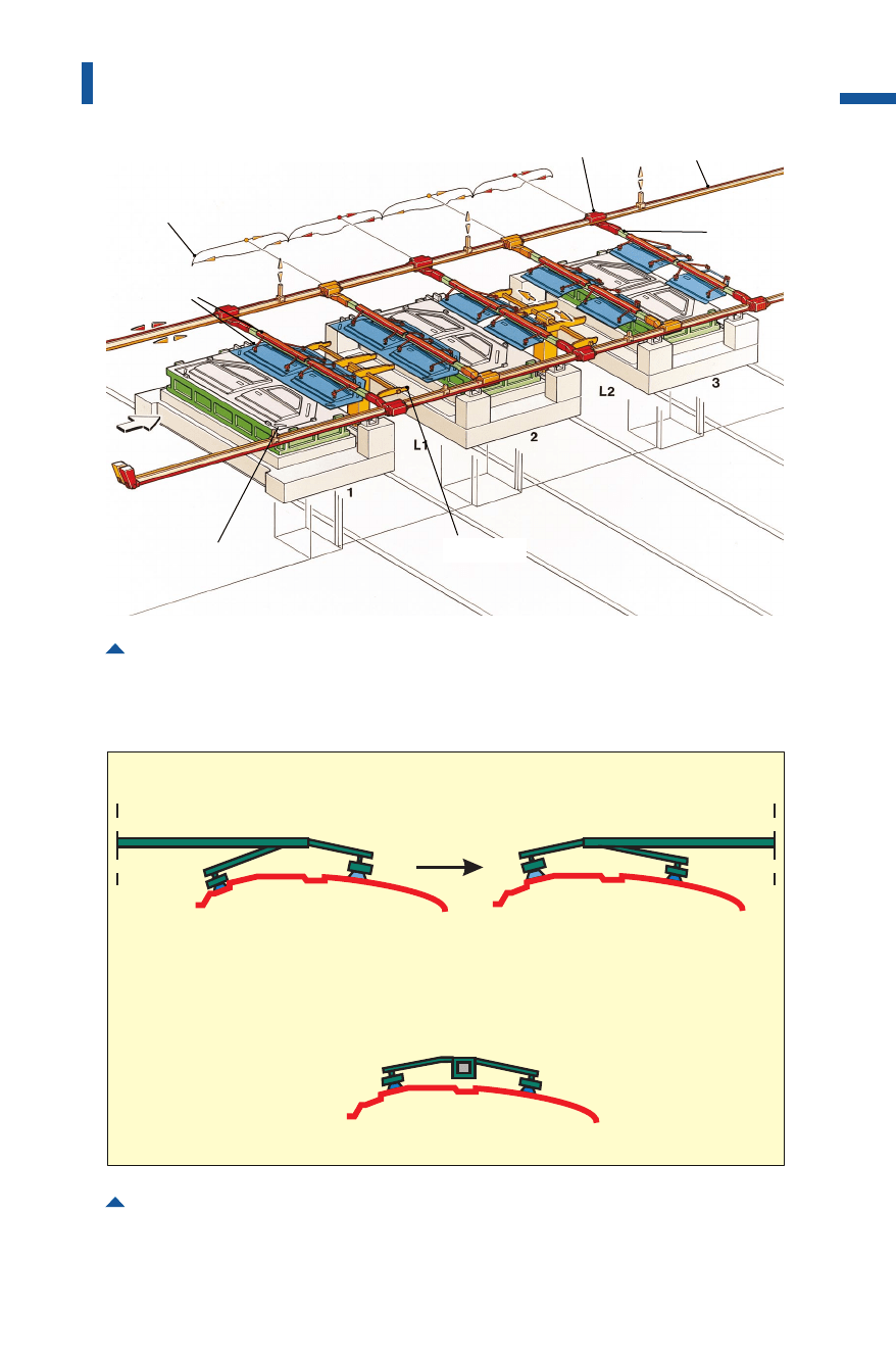
Fig. 4.4.34 Part transport with crossbar transfer system in the production of doors using a
double die
motion curves
carriage
lift beam
crossbar
universal station
double die
part-specific
tooling
Fig. 4.4.35 Positioning of parts on a feeder or robotic arm of a press line and on a crossbar
loading
unloading
loading and unloading
feeder arm of
a press line
crossbar of a
transfer press
Metal Forming Handbook / Schuler (c) Springer-Verlag Berlin Heidelberg 1998
case be sufficiently great to accommodate the crossbars. With a suitable
number and arrangement of the suction cups on the crossbars, it is pos-
sible to transport large one-piece body side panels for passenger cars or
even minivan-type vehicles. The blank dimensions for this type of side
panel can be up to 4,200 31,900 mm.
In order to achieve smooth transfer in conjunction with maximum
output, the movement sequences are computer-optimized (Fig. 4.4.36).
Composite carbon fiber materials are used for the crossbars in order to
improve rigidity, damping and to reduce mass. This permits more reli-
able part transport to be achieved even at high stroking rates.
With the use of universal stations between the uprights, it is possible
to achieve an optimum degree of production flexibility (Fig. 4.4.37and
4.4.34).Program control of up to five axes allows the transport of parts
into the ideal position for subsequent operations, thus reducing the
expense of the dies and improving the reliability of die functions.
Furthermore, the universal stations allow the crossbars to assume an
asymmetrical parking position during die closure. This means a marked
reduction in the length of the part transfer and consequently an
246
Sheet metal forming and blanking
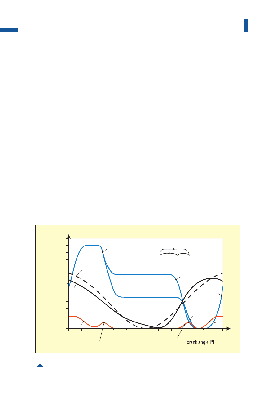
Fig. 4.4.36 Motion diagram of a crossbar transfer press
unloading,parkedposition
loading,parkedposition
slide
movement
slide
movement
(slide1)
lifttransfer
stroke
[mm]
2600
2200
1800
1400
1000
600
200
0
0 30 60 90 120 150 180 210 240 270 300
330
360
returnstrokepickup
inparkingposition(2)
returnstroketo
pickuppart(3)
die
parkedposition
universal
station
1
2
3
pickup
lift
pickup
lift
transport
lower
returnstroke
(slide2to5)
Metal Forming Handbook / Schuler (c) Springer-Verlag Berlin Heidelberg 1998
increase in the stroking rate of 10 to 15% without generating high
forces during part acceleration. The motion paths and acceleration val-
ues are calculated once the part family has been defined.
The press concept in which every station is equipped with a separate
slide (Fig. 4.4.38)offers certain advantages over slides which accept sev-
eral dies. For example each slide and therefore each die station can be
individually adjusted concerning height, press force and response of
the overload system. The slide is generally subjected to on-center loads,
as the individual die stations do not influence each other. Forces are
absorbed by the four connecting rods with minimal tilt of the slide. The
slides are guided in eight-way gibs which reduce tilting of the slide (cf.
Fig.3.1.5). The deflection in the direction of transport is reduced in
both the press beds and the slides.
These features ensure – particularly in the case of large dies – an
advantageous effect on part quality and on the service life of dies.
Moreover, it results in reduced die try-out periods and run-in times for
new die sets until production of the first acceptable part.
Separate slides also offer the benefit that the spacing between indi-
vidual dies – still with the advantage of reduced part transfer – increases.
247
Sheet metal forming lines
Fig. 4.4.37 Universal station with three to five programmable axes
part-dependent
contouredtemplate
Metal Forming Handbook / Schuler (c) Springer-Verlag Berlin Heidelberg 1998
As a result, quick die clamps, tooling at the transfer and universal sta-
tions and the dies themselves are more easily accessible, allowing for
more generously dimensioned scrap chutes. Malfunctions are less fre-
quent and easier to locate and remedy. In general, separate slides help
to increase the utilization rate and economy of the press.
In addition to crossbar presses with separate slides described here,
this press type can alternatively be designed to accept several dies under
one slide. This represents a solution at lower capital investment similar
to the solution used in a tri-axis transfer press (Fig. 4.4.27).
Basically this system transfers the parts directly from one die to the
next die without employing universal stations for part repositioning in
between. Consequently, the part transport needs to cover the distance
between die centers with the inclusion of the crossbar parking space
which results in about 20% more horizontal transportation and conse-
quently reduced stroking rate.
Die changing equipment plays a significant role in reducing press
set-up times. Transfer presses are equipped with moving bolsters
248
Sheet metal forming and blanking
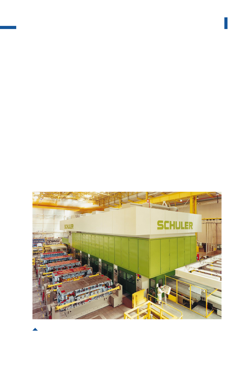
Fig. 4.4.38 Crossbar transfer press with moving bolsters outside the press
nominal press force: 52,000kN; slides:5; work stages: 5; feed pitch: 2,000mm
Metal Forming Handbook / Schuler (c) Springer-Verlag Berlin Heidelberg 1998

(cf. Fig. 3.4.3)for automatic die change. For each die station there are
two moving bolsters. One die set is used for production inside the press,
the other set is located outside the press being prepared for the next
production run (Fig.4.4.38and cf. Fig.3.4.4).This allows the die and
part-specific tooling to be prepared while the press is still producing.
While the lift beams stay in the press, the crossbars and the tooling
are separated by automatic couplings from the lift beams for die change.
They are then positioned on the moving bolster of the die and moved
out of the press at 90°to the direction of part flow. Every die set is
equipped with its own crossbar and suction cup tooling. When setting-
up the moving bolsters outside the press, the crossbars assigned to the
moving bolster are equipped with the tooling required for the next part.
The steps performed when changing dies and resetting all relevant
parameters of the press are executed automatically. These steps include:
deposit and unclamping of top dies, release of crossbar couplings, rais-
ing of lift beams to clear traversing of moving bolsters, exit of moving
bolsters; entry, lowering and centering of new bolsters, clamping of
upper dies, replacing the next crossbars with tooling and contoured
nests of the universal stations.
All the die change parameters are automatically set by a programma-
ble logic control. Accordingly, all the adjustable parameters of the
peripheral press systems such as the destacker or part stacking are
recalled and automatically set (cf. Sect. 4.4.11).
A complete die changeover requires about 10min, as various reset-
ting processes run simultaneously. The individual phases of the die
changing process are locally and centrally displayed on screens for
monitoring purposes.
When manufacturing large parts such as one-piece body sides, in par-
ticular, individual and direct control of the blankholding forces is very
important to achieve good part quality. Just as in tri-axis transfer press-
es, power is transmitted via pressure cylinders to the blank holder
frame. Generally, systems with four displacement cylinders are used.
The fundamental advantage of the hydraulic displacement system,
compared to pneumatic draw cushions, is that the draw cushion force
can be optionally controlled at each individual hydraulic cylinder dur-
ing the drawing process by means of microprocessor-controlled servo
valves. The pressure can be adjusted between 25 and 100% of the rated
pressure(cf. Fig. 3.1.12).
249
Sheet metal forming lines
Metal Forming Handbook / Schuler (c) Springer-Verlag Berlin Heidelberg 1998
Double parts can be most successfully produced (Fig.4.4.39)on
eight-cylinder draw cushions with a split pressure pad. This allows indi-
vidual adjustment of four cylinders per part.
4.4.9Presses for plastics
Metal components are being replaced by plastics in a number of applica-
tions, including the automotive engineering industry. The materials used
here include FRTP (glass fiber-reinforced thermoplastics) and SMC (sheet
molding compound). The manufacture of these parts imposes particu-
250
Sheet metal forming and blanking
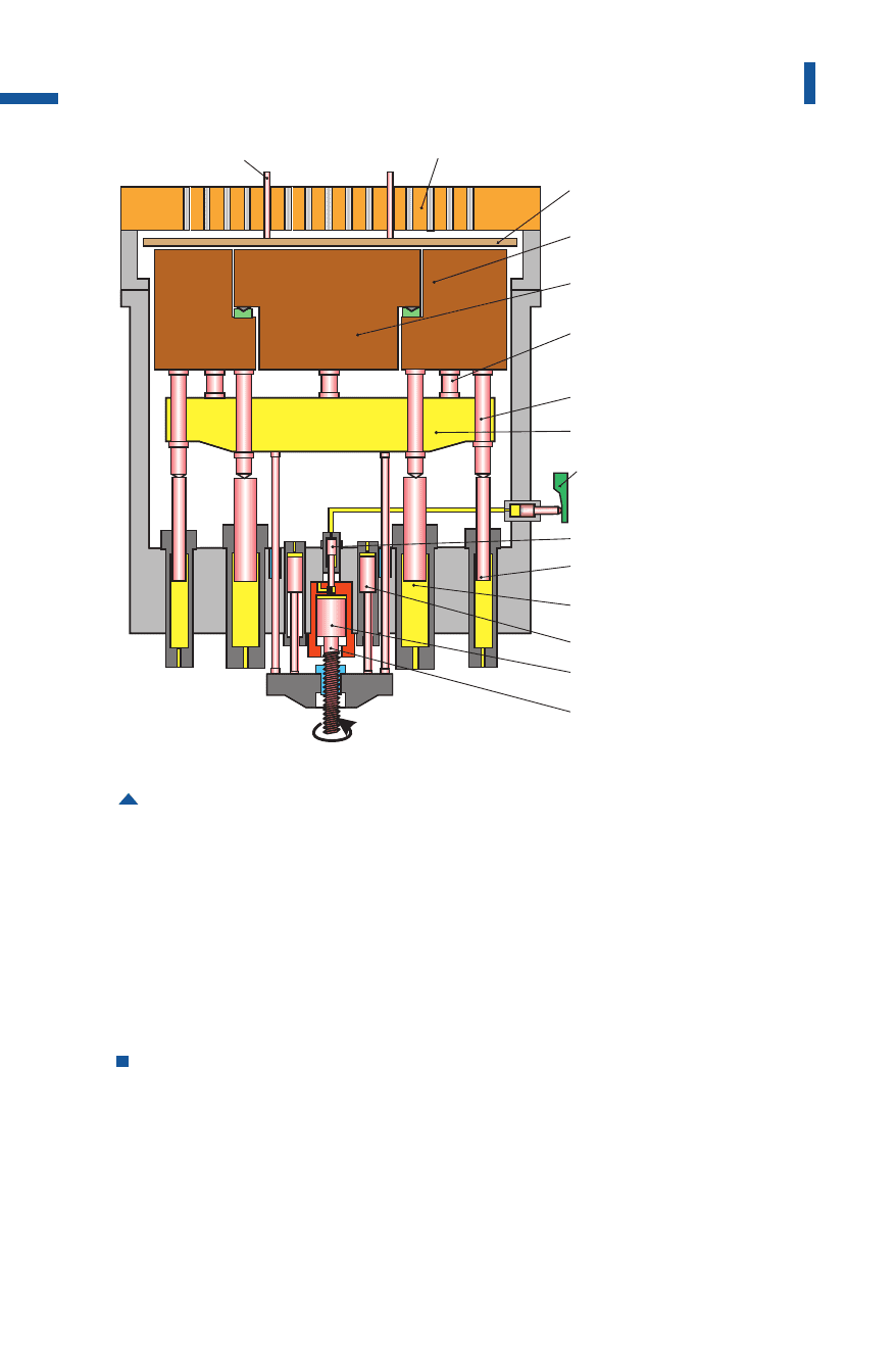
Fig. 4.4.39 Hydraulic draw cushion with eight displacement cylinders and a split
pressure pad
movingboster
pinholdingplate
externalbox
internalbox
connection
pressurecolumn
crossbar
controlcam
pilotcylinder
outsidecylinder
centralcylinder
intermediatestop
acceleratorpiston
strokelimitation
pressurepin
Metal Forming Handbook / Schuler (c) Springer-Verlag Berlin Heidelberg 1998