Altan T. Metal Forming Handbook
Подождите немного. Документ загружается.

protects against overload or in extreme cases against breakage of the
slide, die or press as a result of excessive forces (cf.Fig. 3.2.10).In the
case of transfer presses with high loads at individual stations, a total
press overload system is also provided.
To eject parts that may stick to upper dies, it is possible to equip each
station individually with pneumatic, hydraulic or mechanical ejectors
(cf. Fig.3.2.12).Their ejection force can be adjusted by means of pres-
sure reducing valves or pressure axes. In conjunction with mechanical
hold-back devices, the ejectors can also be used for thin-walled parts.
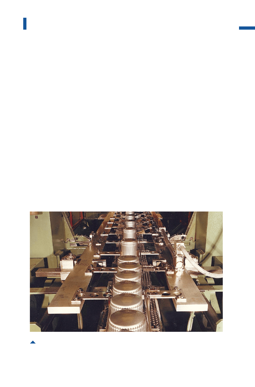
In mechanical transfer presses, parts are transported from one station
to the next by a gripper rail system whose two or three-dimensional
movement is generally coupled mechanically to the slide motion
(Fig. 4.4.24).
In two-dimensional systems, the gripper rails execute only the open-
ing and closing as well as forward and return feed movements. If the
workpieces have to be raised at certain stations of the forming sequence,
this is executed by special grippers. A three-dimensional transport sys-
tem is used in cases where workpieces require a lift motion at most sta-
231
Sheet metal forming lines
Fig. 4.4.24 Tool area of a transfer press for producing oil filter housings
Metal Forming Handbook / Schuler (c) Springer-Verlag Berlin Heidelberg 1998

tions. The entire gripper rail system is then equipped with a lift stroke.
This principle, which is described in Sect. 4.4.7 “tri-axis transfer presses”,
is generally in the production of larger panels.
All three axes of the gripper rail drive systems are positively driven by
double cams. Configuration of the motion curves in accordance with
mathematical principles prevents jerky accelerations – in other words,
no centrifugal effects are created which would jeopardize reliable work-
piece transport. The distance between the gripper rails perpendicular to
the direction of transport can be adjusted infinitely or on a step-by-step
basis. In the case of parts with small dimensions, this eliminates the
need for long grippers and corresponding motion of large masses.
Hydraulic transfer presses
In the case of hydraulic transfer presses, an electrically driven gripper
rail system transports the workpieces from the destacker to the storage
location behind the press (Fig. 4.4.25).
The manufacture of parts using the counter drawing method is gener-
ally used only in hydraulic presses (Fig.4.4.26, cf. Fig.3.1.10and 4.2.4).
The drawing process is performed, generally in two stages, by active draw
cushions in the press bed followed by trimming and flanging of the edge.
The slide closes and displaces the blank holder while the two rear dies
form the edge. The slide reaches its bottom dead center when it makes
contact with mechanical stops. Only after this stage is reached, the parts
are drawn using the punches by switching over the drive pumps from
slide to bed cushion operation. The blanks are held at every die station
using the pre-selected force level acting from above. Once the forming
operation has been completed, the slide opens while the bed cushions
return to their starting positions. The advantage of this forming method
is that no tilting moment acts on the slide during the forming process, as
the two halves of the die set are resting on each other during the entire
drawing operation. Thus, it is possible to achieve a high standard of part
quality and also a favorable energy balance (cf. Sect. 3.3).
If the parts are produced in the transfer press using a single-acting sys-
tem with a draw cushion, large off-center loads can occur if drawing
forces come into effect in the first stations, e. g. in the front-most dies,
while the rear die stations have not yet been subjected to loading. This
situation leads to tilting of the slide, which can be compensated with the
aid of a hydraulic system controlling the slide parallelity (cf. Fig. 3.3.5).
232
Sheet metal forming and blanking
Metal Forming Handbook / Schuler (c) Springer-Verlag Berlin Heidelberg 1998
Within the distance between the die centers – which corresponds at
the same time to the transfer step – the draw cushions and bed ejectors
are located underneath the bolster. Each drawing die set requires its
own draw cushion whose blankholding force can be individually
adjusted for the drawing process, carried out at each individual station
(cf. Sect. 3.1.4). During the upstroke motion of the slide, the bed ejec-
tors raise the workpieces to the transfer plane to allow the gripper rails
to engage the part and transport it forward.
Hydraulic ejectors in the slide help to prevent the formed parts from
sticking in the upper dies. The force and the speed of these ejectors
must be configured in such a way that the parts remain in a defined
position on the lower dies (cf. Fig. 3.2.12).Optionally, it is also possible
to equip the tools with low-cost spring loaded slide ejectors. However,
in this case, the ejection of the parts is not well controlled.
233
Sheet metal forming lines
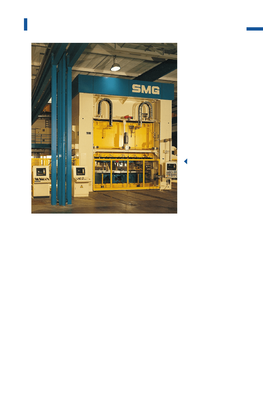
Fig. 4.4.25
Hydraulic transfer
press: nominal press
force: 42,000 kN;
number of stations:
11; feed pitch:
700 mm; slides: 3;
strokes per
minute: 10-28
Metal Forming Handbook / Schuler (c) Springer-Verlag Berlin Heidelberg 1998
4.4.7Large-panel tri-axis transfer presses
During the sixties and seventies, developments in the field of press line
technology led to continuous performance improvement, culminating
in the synchronized press line with fully automatic part transport (cf.
Sect. 4.4.5). As a result of developments in large-panel transfer presses, it
was possible to improve production times per part and to further reduce
capital investment, production and storage costs. In conjunction with
the integrated gripper rail transfer system, this press concept incorporates
all the processing stages required in a press line (Fig. 4.4.27).
Large-panel transfer presses with a distance between die centers of
approx. 2,200 mm and die widths of up to 3,000mm can process large
workpieces measuring up to 2,500 31,500 mm. The forming stations
are moved so close together that several stations can be accommodated
under a single slide. This reduces the space requirement by 50 and
70%. The required power is reduced by 40 to 50% and the investment
by 20 to 40%. Other benefits are gained as a result of reduced man-
234
Sheet metal forming and blanking
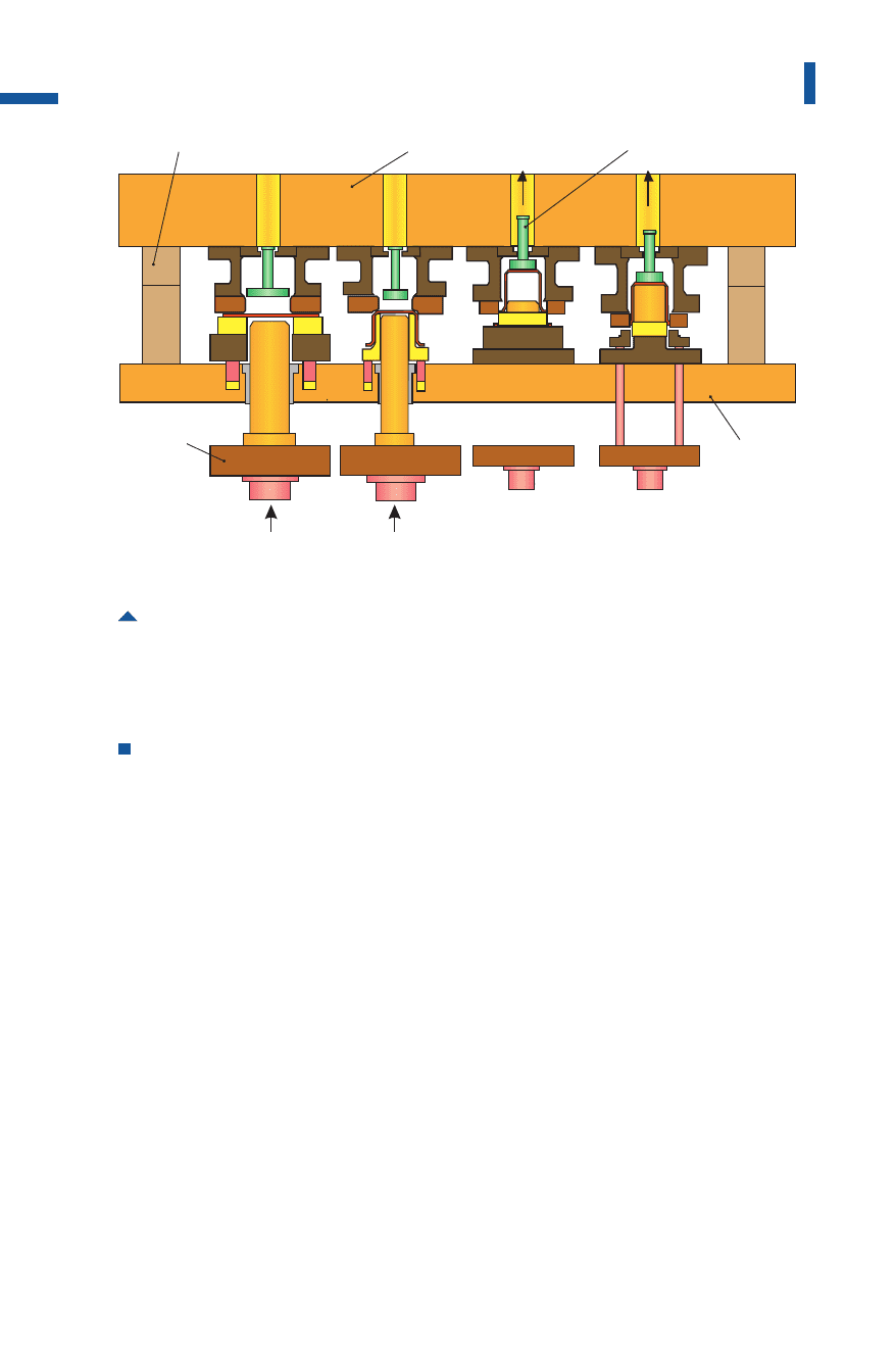
Fig. 4.4.26 Transfer die set for a press with active counter drawing and fixed stops
stop
first
draw
second
draw
edge
trimming
edge
flanging
slide ejector
draw
cushion
bolster
Metal Forming Handbook / Schuler (c) Springer-Verlag Berlin Heidelberg 1998
power requirement, increased safety against accidents and reduction of
noise at lower cost.
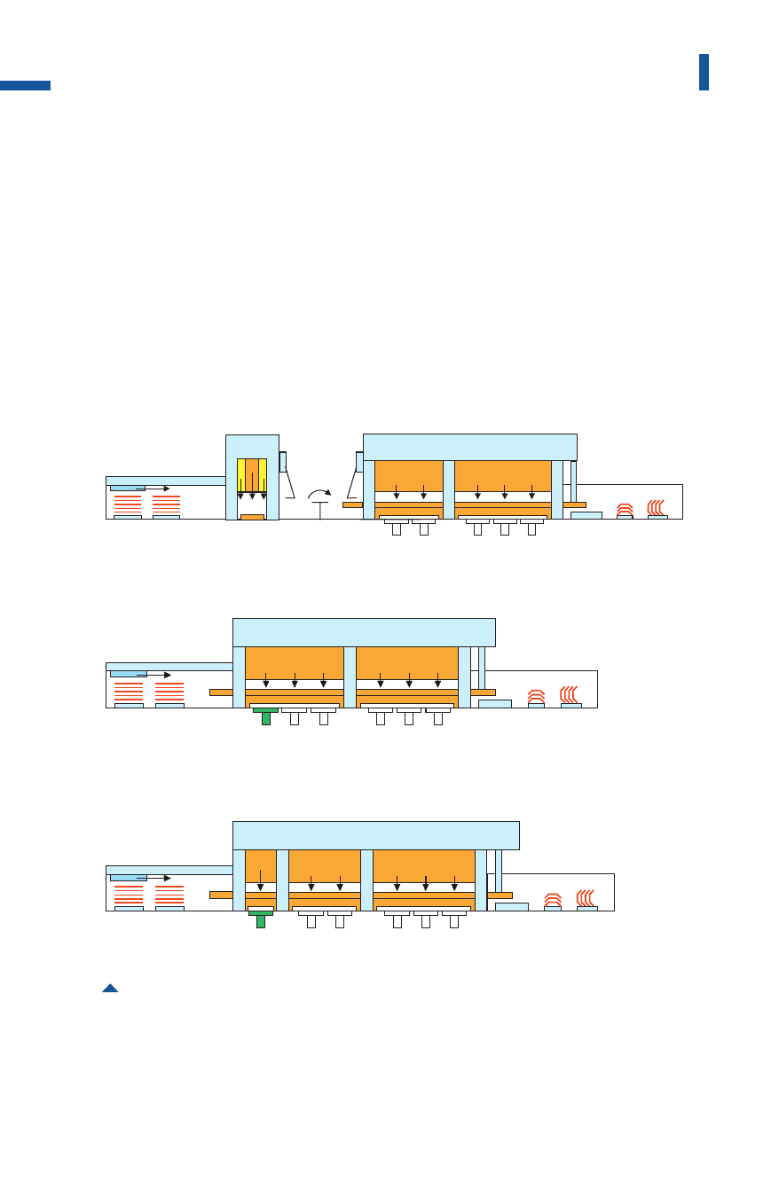
In the initial layouts of press lines, the large-panel transfer press was
combined with a double-action draw press (cf.Fig.3.1.8and Fig. 4.4.28a),
meaning that the drawing technique customary on double-acting press-
es was retained. The additionally required turnover device and syn-
chronization of the presses, however, reduced the output to approx.
12 parts per minute. In addition, due to the use of the turnover device
(cf.Sect.3.1.3), the time required for die changing was considerably
longer. Investment, operation and space costs still substantially exceeded
those of a single-action large-panel transfer press.
235
Sheet metal forming lines
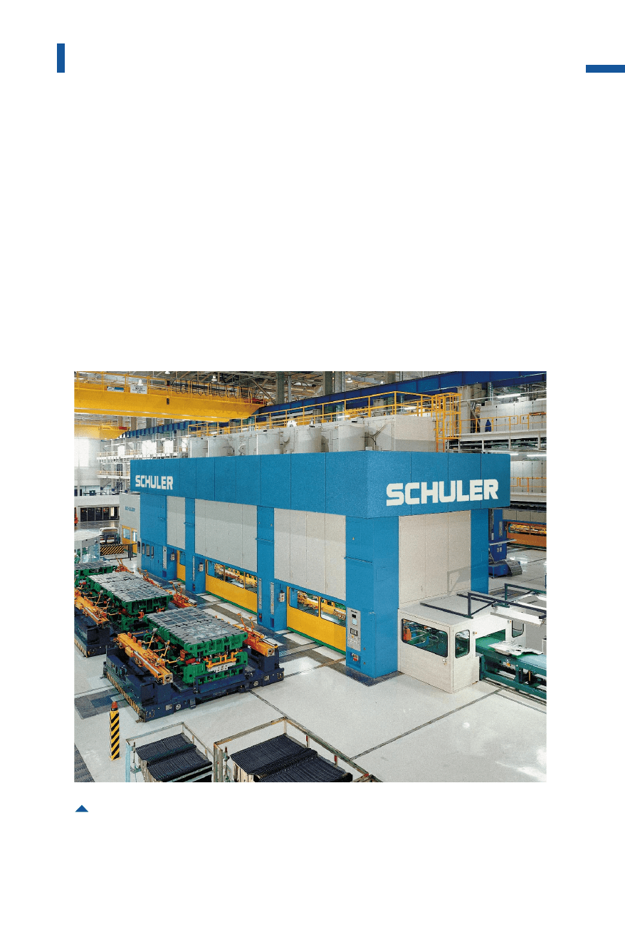
Fig. 4.4.27 Large-panel tri-axis transfer press
nominal press force: 38,000kN; slides:3; work stations: 6;
feed pitch: 2,000mm; strokes per minute: 8-18
Metal Forming Handbook / Schuler (c) Springer-Verlag Berlin Heidelberg 1998
Through the use of recently developed, controlled draw cushions in
the press bed, today it is possible to execute all the necessary produc-
tion steps on a large-panel transfer press (cf. Sect.3.1.4). As workpiece
transport from the first to the last processing station now only takes
place using a single transfer system, higher transport speeds are possi-
ble. Depending on the transfer step, these lines are capable of an output
of between 15 and 25 parts per minute. This corresponds to an increase
in output of some 50% over an automated press line.
236
Sheet metal forming and blanking
Fig. 4.4.28 Large-panel transfer press systems
adouble-action press combined with a transfer press
bpress with three uprights
cpress with four uprights
1
1
1
2
2
2
3
3
3
4
4
4
5
5
5
6
6
6
a
b
c
Metal Forming Handbook / Schuler (c) Springer-Verlag Berlin Heidelberg 1998

Press layout
The design of a large-panel transfer press depends on the number of sta-
tions and the distribution of forces. The four to seven die sets required
for the production of sheet metal parts are distributed over one, two or
three slides. The transfer step depends on the size of the parts. The
slides are guided in eight tracks (cf.Fig.3.1.5). In two- and three-upright
presses, two, three or six die sets are each distributed to one slide
(Fig. 4.4.28c). Here, tilting of the slide can occur as a result of off-center
loads, and must be partially compensated by appropriate countermea-
sures in the die set. In the case of extremely high drawing forces in the
first work station, a four-upright press with a separate slide for the first
station is recommended (Fig. 4.4.28c).
Modern large-panel transfer presses are equipped with link drive sys-
tems in order to reduce the closing speed of the dies (cf. Fig. 3.2.3). The
press crown is split into two parts, the press bed into two or three parts.
The press body is clamped by hydraulically pre-tensioned tie rods (cf.
Fig. 3.1.1).
Automation
Blank feed, workpiece transport, draw cushion control, part removal
and in some cases also the stacking of finished parts as well as electrical
control of the entire transfer press are fully automatic (Fig. 4.4.11).
When changing from one stack to the next and when ejecting double
blanks, continuous operation of the destacker is essential. Supplementary
attachments for washing and lubricating the blank in the destacker are
also frequently integrated. The first blank is separated off the stack by fan-
ning magnets and lifted by suction units. It is then transferred to the cen-
tering station by means of magnetic belts and roller conveyors (cf. Sect.
4.4.4). The feeder to the first station lifts the blank from the centering sta-
tion and transfers it to the first press station. Subsequent workpiece trans-
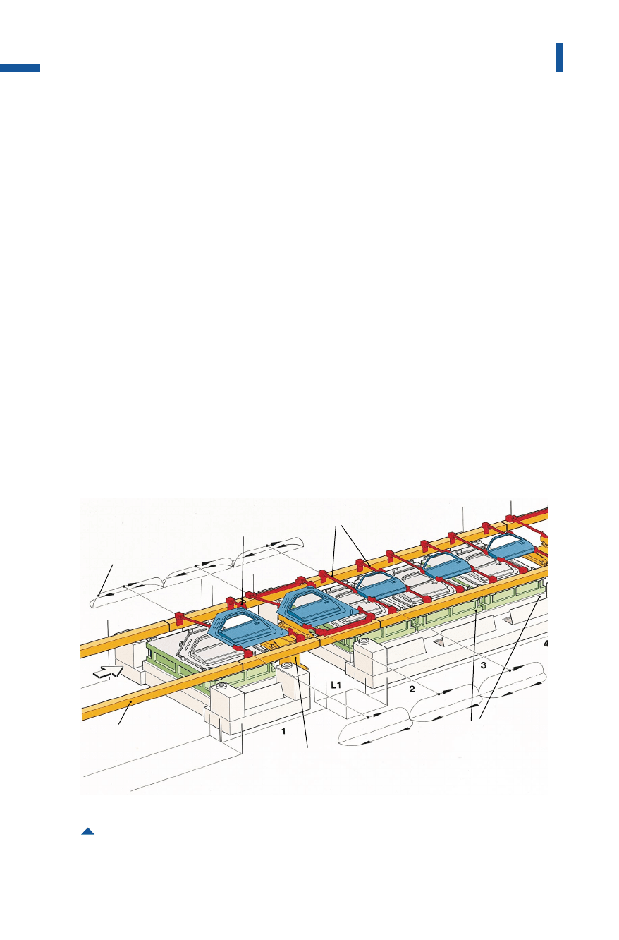
port is performed by the tri-axis gripper rails. The gripper rails index the
workpieces from one station to the next (Fig.4.4.29).Depending on the
blank geometry, the rails are equipped with pneumatically actuated active
grippers or shovels which support the workpiece during transport. In
order to achieve a higher output, the gripper rail mechanism is manufac-
tured for optimum weight savings as a box-type construction using hol-
low profiles. The entire transfer system is electronically monitored to
check for part presence, position and other functions.
237
Sheet metal forming lines
Metal Forming Handbook / Schuler (c) Springer-Verlag Berlin Heidelberg 1998
If there is an upright located after a die station, the grippers deposit
the part on an intermediate station. The three movements executed by
the gripper rails are performed in the longitudinal direction to trans-
port the parts from one station to the next, in the transverse direction
in the form of a closing movement for gripping the workpieces and in
the vertical direction to lift out the drawn parts. The path covered by
the gripper rails in the longitudinal direction is equal to the distance
between die centers.
The longitudinal movement of the gripper rails is actuated directly
from the press drive via intermediate gears, cams and cam levers. The
closing boxes for lifting and lowering, and for opening and closing the
gripper rails, are driven via cam levers and thrust rods.
Thus, part transfer is mechanically synchronized with the press drive
system and it is therefore precisely reproducible. It is particularly bene-
ficial for the entire transfer drive system to be located above floor level,
as this reduces distances and also changes in the direction of motions.
Lower masses, less strain and less play are the result thus permitting a
238
Sheet metal forming and blanking
Fig. 4.4.29 Transportation of parts using mechanically driven gripper rail transfer
motion curve
shovel
part-specific tooling
gripper rail
intermediate station
transfer die
Metal Forming Handbook / Schuler (c) Springer-Verlag Berlin Heidelberg 1998
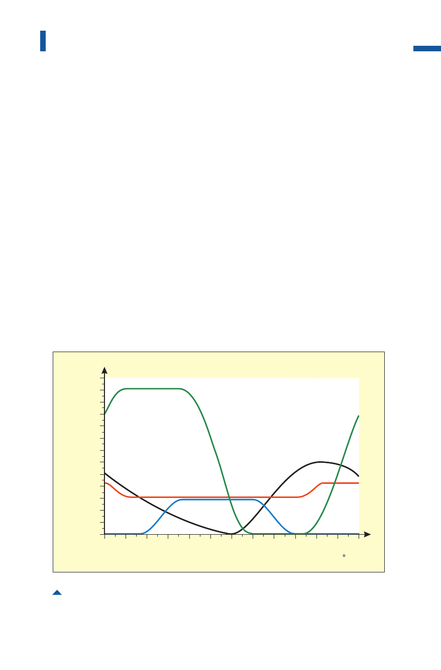
higher stroking rate and reliable part transport. A special computer
program optimizes the motion curve of the transfer movements regard-
ing mass and acceleration so that the shortest possible cycle times
and extremely smooth movements are ensured for all stroking rates
(Fig. 4.4.30).
Motion curves are established for each transfer system and they are
used to check the clearance of the gripper rail system relative to the die
movement. A safety clearance of at least 20mm must be ensured
between the tool and the curve in each case. All elements which may
impede this clearance, such as cam drives or gib elements must be tak-
en into consideration (cf. Sect. 4.1.6).
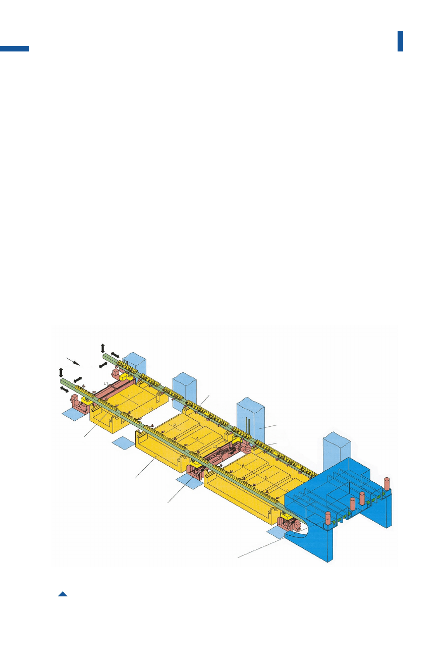
Electrically driven transfer
Instead of mechanical transfer systems, electrically driven systems can
also be used for large-panel presses (Fig. 4.4.31). The path, acceleration
and speed values of electrical transfers can be freely programmed,
which allows the system to be adjusted to different sets of dies.
239
Sheet metal forming lines
Fig. 4.4.30 Motion diagram of a tri-axis transfer system
slidemovement
parttransport
bytransfer
transferreturn
withoutpart
lift
gripper
rails
lowergripperrails
opengripper
rails
closegripper
rails
stroke
[mm]
crankangle[]
2600
2200
1800
1400
1000
600
200
0
0 30 60 90 120 150 180 210 240 270 300 330 360
Metal Forming Handbook / Schuler (c) Springer-Verlag Berlin Heidelberg 1998
Workpiece-specific axis data, lifting strokes, closing distances and
where applicable also transfer steps are entered into the press control
system. Electrical transfers make particular sense wherever just-in-time
production of small batch sizes is called for (Fig.4.4.32).Here, the trans-
port system can be adjusted to a different number of stations, in some
cases different distances between die centers and other parameters by
accessing the values for each part from the data memory. However, for
reasons of safety, this high degree of flexibility means compromising
on cycle speeds in comparison with mechanically coupled transfer
systems.
In the case of gripper rails for high stroking rates with high values of
acceleration and speed, extremely light composite materials and alu-
minium alloys are used.
240
Sheet metal forming and blanking
Fig. 4.4.31 Layout of an electrical transfer system
part-specific tooling
press upright
transverse
drive
direction of
transport
gripper rail
moving bolster
lift / lower drive
longitudinal drive
Metal Forming Handbook / Schuler (c) Springer-Verlag Berlin Heidelberg 1998