ALSTOM T&D. Network Protection And Automation Guide (NPAG)
Подождите немного. Документ загружается.

Chapter 16 Transformer and Transformer Feeder Protection
16-11
16.10 COMBINED DIFFERENTIAL AND
RESTRICTED EARTH FAULT SCHEMES
The advantages to be obtained by the use of restricted earth
fault protection, discussed in Section 16.7 lead to the system
being frequently used in conjunction with an overall differential
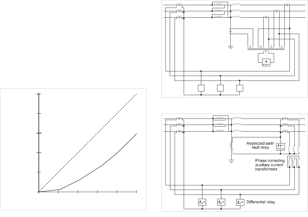
system. The importance of this is shown in Figure 16.12 from
which it will be seen that if the neutral of a star-connected
winding is earthed through a resistance of one per unit, an
overall differential system having an effective setting of 20%
will detect faults in only 42% of the winding from the line end.
020406080100
0
20
40
60
80
100
D
i
f
f
er
e
nt
i
al
pr
o
t
e
c
t
i
o
n
Percentage of winding protected
Primary operating current
(percentage of rated current)
Restrict
ed
e
art
h f
au
lt
protection
Figure 16.12: Amount of winding protected when transformer is
resistance earthed and ratings of transformer and resistor are equal
Implementation of a combined differential/REF protection
scheme is made easy if a numerical relay with software
ratio/phase compensation is used. All compensation is made
internally in the relay.
Where software ratio/phase correction is not available, either a
summation transformer or auxiliary CTs can be used. The
connections are shown in Figure 16.13 and Figure 16.14
respectively.
Care must be taken in calculating the settings, but the only
significant disadvantage of the Combined Differential/REF
scheme is that the REF element is likely to operate for heavy
internal faults as well as the differential elements, thus making
subsequent fault analysis somewhat confusing. However, the
saving in CTs outweighs this disadvantage.
I
d
I
d
I
d
>
I
earth fault
Restricted
relay
Differential relay
Figure 16.13: Combined differential and earth fault protection using
summation current transformer
Figure 16.14: Combined differential and restricted earth fault
protection using auxiliary CTs
16.10.1 Application When an Earthing Transformer is
Connected Within the Protected Zone
A delta-connected winding cannot deliver any zero sequence
current to an earth fault on the connected system, any current
that does flow is in consequence of an earthed neutral
elsewhere on the system and will have a 2-1-1 pattern of
current distribution between phases. When the transformer in
question represents a major power feed, the system may be
earthed at that point by an earthing transformer or earthing
reactor. They are frequently connected to the system, close to
the main supply transformer and within the transformer
protection zone. Zero sequence current that flows through the
earthing transformer during system earth faults will flow
through the line current transformers on this side, and,
without an equivalent current in the balancing current
transformers, will cause unwanted operation of the relays.
The problem can be overcome by subtracting the appropriate
component of current from the main CT output. The earthing
transformer neutral current is used for this purpose. As this
represents three times the zero sequence current flowing, ratio
correction is required. This can take the form of interposing
© 2011 Alstom Grid. Single copies of this document may be filed or printed for personal non-commercial use and must include this
copyright notice but may not be copied or displayed for commercial purposes without the prior written permission of Alstom Grid.
Network Protection & Automation Guide
16-12
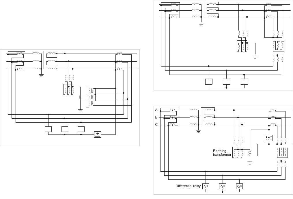
CT’s of ratio 1/0.333, arranged to subtract their output from
that of the line current transformers in each phase, as shown
in Figure 16.15. The zero sequence component is cancelled,
restoring balance to the differential system. Alternatively,
numerical relays may use software to perform the subtraction,
having calculated the zero sequence component internally.
C
A
B
Earthing
transformer
Differential relay
Restricted earth fault relay
1/0.333
>
I
I
d
> I
d
> I
d
>
Figure 16.15: Differential protection with in-zone earthing
transformer, with restricted earth fault relay
A high impedance relay element can be connected in the
neutral lead between current transformers and differential
relays to provide restricted earth fault protection to the
winding.
As an alternative to the above scheme, the circulating current
system can be completed via a three-phase group of
interposing transformers that are provided with tertiary
windings connected in delta. This winding effectively short-
circuits the zero sequence component and thereby removes it
from the balancing quantities in the relay circuit; see Figure
16.16.
Provided restricted earth fault protection is not required, the
scheme shown in Figure 16.16 has the advantage of not
requiring a current transformer, with its associated mounting
and cabling requirements, in the neutral-earth conductor. The
scheme can also be connected as shown in Figure 16.17 when
restricted earth fault protection is needed.
C
A
B
Differential relay
Earthing
transformer
I
d
> I
d
> I
d
>
Figure 16.16: Differential protection with in-zone earthing
transformer; no earth fault relay
Figure 16.17: Differential protection with in-zone earthing
transformer, with alternative arrangement of restricted earth fault
relay
16.11 EARTHING TRANSFORMER
PROTECTION
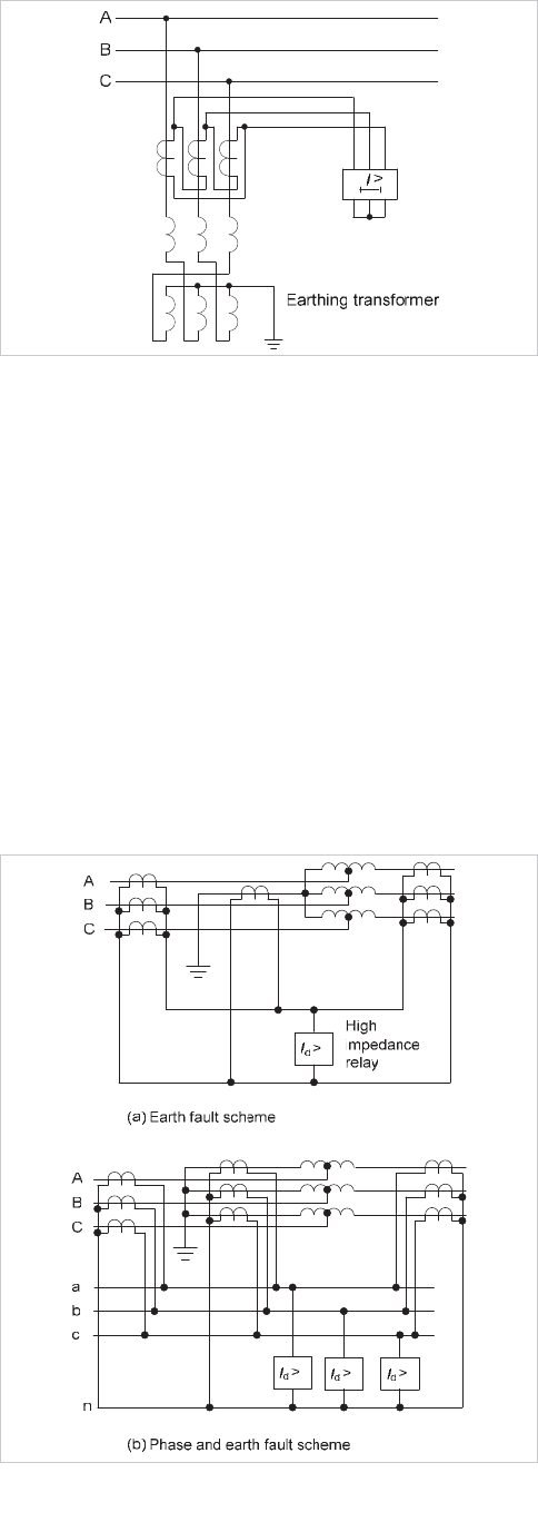
Earthing transformers not protected by other means can use
the scheme shown in Figure 16.18. The delta-connected
current transformers are connected to an overcurrent relay
having three phase-fault elements. The normal action of the
earthing transformer is to pass zero sequence current. The
transformer equivalent current circulates in the delta formed
by the CT secondaries without energising the relay. The latter
may therefore be set to give fast and sensitive protection
against faults in the earthing transformer itself.
© 2011 Alstom Grid. Single copies of this document may be filed or printed for personal non-commercial use and must include this
copyright notice but may not be copied or displayed for commercial purposes without the prior written permission of Alstom Grid.
Chapter 16 Transformer and Transformer Feeder Protection
16-13
Figure 16.18: Earthing transformer protection
16.12 AUTOTRANSFORMER PROTECTION
Autotransformers are used to couple EHV power networks if
the ratio of their voltages is moderate. An alternative to
Differential Protection that can be applied to autotransformers
is protection based on the application of Kirchhoff's law to a
conducting network, namely that the sum of the currents
flowing into all external connections to the network is zero.
A circulating current system is arranged between equal ratio
current transformers in the two groups of line connections and
the neutral end connections. If one neutral current
transformer is used, this and all the line current transformers
can be connected in parallel to a single element relay,
providing a scheme responsive to earth faults only; see Figure
16.19(a).
Figure 16.19: Protection of auto-transformer by high impedance
differential relays
If current transformers are fitted in each phase at the neutral
end of the windings and a three-element relay is used, a
differential system can be provided, giving full protection
against phase and earth faults; see Figure 16.19(b). This
provides high-speed sensitive protection. It is unaffected by
ratio changes on the transformer due to tap-changing and is
immune to the effects of magnetising inrush current.
It does not respond to interturn faults, a deficiency that is
serious in view of the high statistical risk quoted in Section
16.1. Such faults, unless otherwise cleared, will be left to
develop into earth faults, by which time considerably more
damage to the transformer will have occurred.
In addition, this scheme does not respond to any fault in a
tertiary winding. Unloaded delta-connected tertiary windings
are often not protected; alternatively, the delta winding can be
earthed at one point through a current transformer that
energises an instantaneous relay. This system should be
separate from the main winding protection. If the tertiary
winding earthing lead is connected to the main winding
neutral above the neutral current transformer in an attempt to
make a combined system, there may be ‘blind spots’ which the
protection cannot cover.
16.13 OVERFLUXING PROTECTION
The effects of excessive flux density are described in Section
16.2.8. Overfluxing arises principally from the following
system conditions:
x high system voltage
x low system frequency
x geomagnetic disturbances
The latter results in low frequency earth currents circulating
through a transmission system.
Since momentary system disturbances can cause trans
ient
overfluxing that is not dangerous, time delayed tripping is
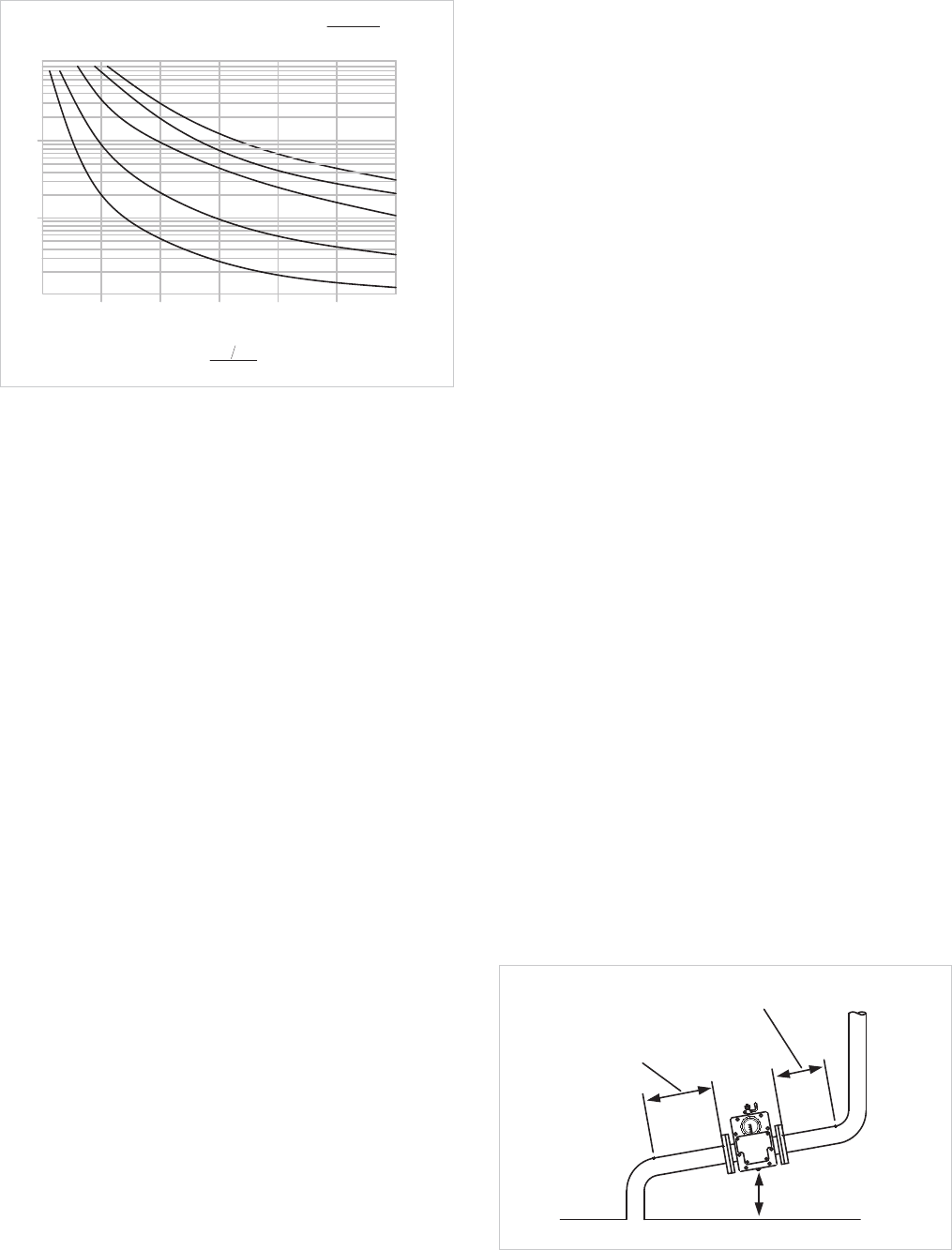
required. The normal protection is an IDMT or definite time
characteristic, initiated if a defined V/f threshold is exceeded.
Often separate alarm and trip elements are provided. The
alarm function would be definite time-delayed and the trip
function would be an IDMT characteristic. A typical
characteristic is shown in Figure 16.20.
Geomagnetic disturbances may result in overfluxing without
the V/f threshold being exceeded. Some relays provide a 5
th
harmonic detection feature, which can be used to detect such
a condition, as levels of this harmonic rise under overfluxing
conditions.
© 2011 Alstom Grid. Single copies of this document may be filed or printed for personal non-commercial use and must include this
copyright notice but may not be copied or displayed for commercial purposes without the prior written permission of Alstom Grid.
Network Protection & Automation Guide
16-14
1
10
100
1000
Operating
time (s)
u
2
0. 8 0. 18 K
t
M1
K=63
K=40
K=20
K=1
K=5
1 1.1 1.2 1.3 1.4 1.5 1.6
Vf
M
Setting
Figure 16.20: Typical IDMT characteristic for overfluxing protection
16.14 TANK-EARTH PROTECTION
This is also known as Howard protection. If the transformer
tank is nominally insulated from earth (an insulation resistance
of 10 ohms being sufficient) earth fault protection can be
provided by connecting a relay to the secondary of a current
transformer the primary of which is connected between the
tank and earth. This scheme is similar to the frame-earth fault
busbar protection described in Chapter 15.
16.15 OIL AND GAS DEVICES
All faults below oil in an oil-immersed transformer result in
localised heating and breakdown of the oil; some degree of
arcing will always take place in a winding fault and the
resulting decomposition of the oil will release gases. When the
fault is of a very minor type, such as a hot joint, gas is released
slowly, but a major fault involving severe arcing causes a very
rapid release of large volumes of gas as well as oil vapour. The
action is so violent that the gas and vapour do not have time
to escape but instead build up pressure and bodily displace the
oil.
When such faults occur in transformers having oil
conservators, the fault causes a blast of oil to pass up the relief
pipe to the conservator. A Buchholz relay is used to protect
against such conditions. Devices responding to abnormally
high oil pressure or rate-of-rise of oil pressure are also
available and may be used in conjunction with a Buchholz
relay.
16.15.1 Oil Pressure Relief Devices
The simplest form of pressure relief device is the widely used
‘frangible disc’ that is normally located at the end of an oil
relief pipe protruding from the top of the transformer tank.
The surge of oil caused by a serious fault bursts the disc, so
allowing the oil to discharge rapidly. Relieving and limiting the
pressure rise avoids explosive rupture of the tank and
consequent fire risk. Outdoor oil-immersed transformers are
usually mounted in a catchment pit to collect and contain spilt
oil (from whatever cause), thereby minimising the possibility of
pollution.
A drawback of the frangible disc is that the oil remaining in the
tank is left exposed to the atmosphere after rupture. This is
avoided in a more effective device, the sudden pressure relief
valve, which opens to allow discharge of oil if the pressure
exceeds a set level, but closes automatically as soon as the
internal pressure falls below this level. If the abnormal
pressure is relatively high, the valve can operate within a few
milliseconds, and provide fast tripping when suitable contacts
are fitted.
The device is commonly fitted to power transformers rated at
2MVA or higher, but may be applied to distribution
transformers rated as low as 200kVA, particularly those in
hazardous areas.
16.15.2 Sudden Pressure Rise Relay
This device detects rapid rise of pressure rather than absolute
pressure and thereby can respond even quicker than the
pressure relief valve to sudden abnormally high pressures.
Sensitivities as low as 0.07bar/s are attainable, but when fitted
to forced-cooled transformers the operating speed of the
device may have to be slowed deliberately to avoid spurious
tripping during circulation pump starts. Alternatively, sudden
pressure rise relays may have their output supervised by
instantaneous high-set overcurrent elements.
16.15.3 Buchholz Protection
Buchholz protection is normally provided on all transformers
fitted with a conservator. The Buchholz relay is contained in a
cast housing which is connected in the pipe to the conservator,
as in Figure 16.21.
76mm typical
Transformer
Conservator
3 x internal pipe
diameter (min)
5 x internal pipe
diameter (min)
Figure 16.21: Buchholz relay mounting arrangement
© 2011 Alstom Grid. Single copies of this document may be filed or printed for personal non-commercial use and must include this
copyright notice but may not be copied or displayed for commercial purposes without the prior written permission of Alstom Grid.
Chapter 16 Transformer and Transformer Feeder Protection
16-15
A typical Buchholz relay will have two sets of contacts. One is
arranged to operate for slow accumulations of gas, the other
for bulk displacement of oil in the event of a heavy internal
fault. An alarm is generated for the former, but the latter is
usually direct-wired to the CB trip relay.
The device will therefore give an alarm for the following fault
conditions, all of which are of a low order of urgency.
x hot spots on the core due to short circuit of lamination
insulation
x core bolt insulation failure
x faulty joints
x interturn faults or other winding faults involving only
lower power infeeds
x loss of oil due to leakage
When a major winding fault occurs, this causes a surge of oil,
which displaces the lower float and thus causes isolation of
the
transformer. This action will take place for:
x all severe winding faults, either to earth or interphase
x loss of oil if allowed to continue to a dangerous degree
An inspection window is usually provided on either side
of the
gas collection space. Visible white or yellow gas indicates that
insulation has been burnt, while black or grey gas indicates the
presence of, dissociated oil. In these cases the gas will
probably be inflammable, whereas released air will not. A vent
valve is provided on the top of the housing for the gas to be
released or collected for analysis. Transformers with forced oil
circulation may experience oil flow
to/from the conservator on
starting/stopping of the pumps. The Buchholz relay must not
operate in this circumstance.
Cleaning operations may cause aeration of the oil. Under such
conditions, tripping of the transformer due to Buchholz
operation should be inhibited for a suitable period.
Because of its universal response to faults within the
transformer, some of which are difficult to detect by other
means, the Buchholz relay is invaluable, whether regarded as a
main protection or as a supplement to other protection
schemes. Tests carried out by striking a high voltage arc in a
transformer tank filled with oil, have shown that operation
times of 0.05s-0.1s are possible. Electrical protection is
generally used as well, either to obtain faster operation for
heavy faults, or because Buchholz relays have to be prevented
from tripping during oil maintenance periods. Conservators
are fitted to oil-cooled transformers above 1000kVA rating,
except those to North American design practice that use a
different technique.
16.16 TRANSFORMER-FEEDER PROTECTION
A transformer-feeder comprises a transformer directly
connected to a transmission circuit without the intervention of
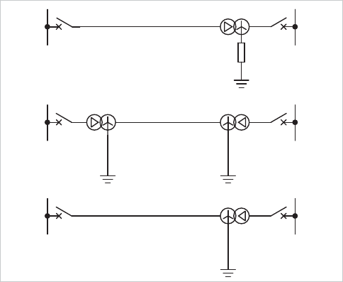
switchgear. Examples are shown in Figure 16.22.
HV LV
HV LV
HV LV
HVLV
Figure
16.22
: Typical transformer-feeder circuits
.
The saving in switchgear so achieved is offset by increased
complication in the necessary protection. The primary
requirement is intertripping, since the feeder protection remote
from the transformer will not respond to the low current fault
conditions that can be detected by restricted earth fault and
Buchholz protections.
Either unrestricted or restricted protection can be applied;
moreover, the transformer-feeder can be protected as a single
zone or be provided with separate protections for the feeder
and the transformer. In the latter case, the separate
protections can both be unit type systems. An adequate
alternative is the combination of unit transformer protection
with an unrestricted system of feeder protection, plus an
intertripping feature.
16.16.1 Non-Unit Schemes
The following sections describe how non-unit schemes are
applied to protect transformer-feeders against various types of
fault.
16.16.1.1 Feeder phase and earth faults
High-speed protection against phase and earth faults can be
provided by distance relays located at the end of the feeder
remote from the transformer. The transformer constitutes an
appreciable lumped impedance. It is therefore possible to set a
distance relay zone to cover the whole feeder and reach part
way into the transformer impedance. With a normal tolerance
on setting thus allowed for, it is possible for fast Zone 1
protection to cover the whole of the feeder with certainty
© 2011 Alstom Grid. Single copies of this document may be filed or printed for personal non-commercial use and must include this
copyright notice but may not be copied or displayed for commercial purposes without the prior written permission of Alstom Grid.
Network Protection & Automation Guide
16-16
without risk of over-reaching to a fault on the low voltage side.
Although the distance zone is described as being set ’half way
into the transformer’, it must not be thought that half the
transformer winding will be protected. The effects of auto-
transformer action and variations in the effective impedance of
the winding with fault position prevent this, making the
amount of winding beyond the terminals which is protected
very small. The value of the system is confined to the feeder,
which, as stated above, receives high-speed protection
throughout.
16.16.1.2 Feeder phase faults
A distance scheme is not, for all practical purposes, affected by
varying fault levels on the high voltage busbars and is therefore
the best scheme to apply if the fault level may vary widely. In
cases where the fault level is reasonably constant, similar
protection can be obtained using high set instantaneous
overcurrent relays. These should have a low transient over-
reach (t), defined as:
%100u
F
FS
I
II
where:
I
s
= setting current
I
F
= steady state r.m.s value of the fault current, which when
fully offset, just operates the relay.
The instantaneous overcurrent relays must be set without risk
of them operating for faults on the remote side of the
transformer.
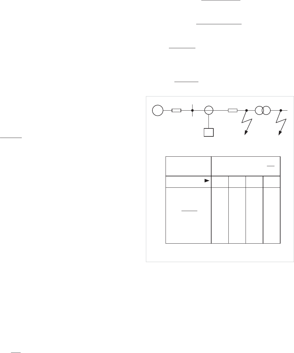
Referring to Figure 16.23, the required setting to ensure that
the relay will not operate for a fully offset fault
I
F2
is given by:
2
12.1
Fs
ItI
Where
I
F2
is the fault current under maximum source
conditions, that is, when
Z
S
is minimum, and the factor of 1.2
covers possible errors in the system impedance details used for
calculation of
I
F2
, together with relay and CT errors.
As it is desirable for the instantaneous overcurrent protection
to clear all phase faults anywhere within the feeder under
varying system operating conditions, it is necessary to have a
relay setting less than
I
F1
to ensure fast and reliable operation.
Let the setting ratio resulting from setting
I
s
be:
1F
s
I
I
r
Therefore,
21
12.1
FF
ItIr
Hence,
TLS
LS
ZZZ
ZZ
tr
12.1
LS
LS
ZZx
ZZ
t
1
12.1
x
t
1
12.1
where:
LS
T
ZZ
Z
x
Z
S
Z
L
Z
T
I
F1
I
F2
over-reach (%)
Transient
0.25
1.0
0.5
2.0
8.0
4.0
Setting ratio
1.01 1.20 1.44 1.92
0.84
0.42
0.63
0.14
0.25
0.50
0.30
0.17
1.00
0.75
0.60
0.36
0.20
1.20
0.90
0.80
0.48
0.27
1.60
1.20
I
S
= Relay setting =
t = Transient over-reach (p.u.)
52550100
>
I
>
T
SL
Z
x
ZZ
S
F1
I
r
I
F2
1.2 1 t I
~
Figure 16.23: Over-reach considerations in the application of
transformer-feeder protection
It can be seen that for a given transformer size, the most
sensitive protection for the line will be obtained by using relays
with the lowest transient overreach. It should be noted that
where
r
is greater than 1, the protection will not cover the
whole line. Also, any increase in source impedance above the
minimum value will increase the effective setting ratios above
those shown. The instantaneous protection is usually applied
with a time delayed overcurrent element having a lower
current setting. In this way, instantaneous protection is
provided for the feeder, with the time-delayed element
covering faults on the transformer.
When the power can flow in the transformer-feeder in either
© 2011 Alstom Grid. Single copies of this document may be filed or printed for personal non-commercial use and must include this
copyright notice but may not be copied or displayed for commercial purposes without the prior written permission of Alstom Grid.
Chapter 16 Transformer and Transformer Feeder Protection
16-17
direction, overcurrent relays will be required at both ends. In
the case of parallel transformer-feeders, it is essential that the
overcurrent relays on the low voltage side be directional,
operating only for fault current fed into the transformer-feeder,
as described in Section 9.14.3.
16.16.1.3 Earth faults
Instantaneous restricted earth fault protection is normally
provided. When the high voltage winding is delta connected, a
relay in the residual circuit of the line current transformers
gives earth fault protection which is fundamentally limited to
the feeder and the associated delta-connected transformer
winding. The latter is unable to transmit any zero sequence
current to a through earth fault.
When the feeder is associated with an earthed star-connected
winding, normal restricted earth fault protection as described
in Section 16.7 is not applicable because of the remoteness of
the transformer neutral.
Restricted protection can be applied using a directional earth
fault relay. A simple sensitive and high-speed directional
element can be used, but attention must be paid to the
transient stability of the element. Alternatively, a directional
IDMT relay may be used, the time multiplier being set low.
The slight inverse time delay in operation will ensure that
unwanted transient operation is avoided.
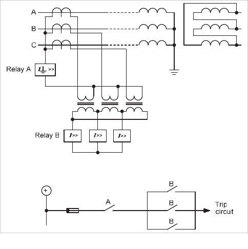
When the supply source is on the high voltage star side, an
alternative scheme that does not require a voltage transformer
can be used. The scheme is shown in Figure 16.24. For the
circuit breaker to trip, both relays
A
and
B
must operate, which
will occur for earth faults on the feeder or transformer winding.
External earth faults cause the transformer to deliver zero
sequence current only, which will circulate in the closed delta
connection of the secondary windings of the three auxiliary
current transformers. No output is available to relay
B
.
Through phase faults will operate relay
B
, but not the residual
relay
A
. Relay
B
must have a setting above the maximum
load. As the earthing of the neutral at a receiving point is likely
to be solid and the earth fault current will therefore be
comparable with the phase fault current, high settings are not
a serious limitation.
Figure 16.24: Instantaneous protection of transformer-feeder
Earth fault protection of the low voltage winding will be
provided by a restricted earth fault system using either three or
four current transformers, according to whether the winding is
delta or star-connected, as described in Section 16.7.
16.16.1.4 In-zone capacitance
The feeder portion of the transformer-feeder will have an
appreciable capacitance between each conductor and earth.
During an external earth fault the neutral will be displaced,
and the resulting zero sequence component of voltage will
produce a corresponding component of zero sequence
capacitance current. In the limiting case of full neutral
displacement, this zero sequence current will be equal in value
to the normal positive sequence current.
The resulting residual current is equal to three times the zero
sequence current and hence to three times the normal line
charging current. The value of this component of in-zone
current should be considered when establishing the effective
setting of earth fault relays.
16.16.2 Unit Schemes
The basic differences between the requirements of feeder and
transformer protections lie in the limitation imposed on the
transfer of earth fault current by the transformer and the need
for high sensitivity in the transformer protection, suggesting
that the two components of a transformer-feeder should be
protected separately. This involves mounting current
transformers adjacent to, or on, the high voltage terminals of
the transformer. Separate current transformers are desirable
for the feeder and transformer protections so that these can be
arranged in two separate overlapping zones. The use of
common current transformers is possible, but may involve the
© 2011 Alstom Grid. Single copies of this document may be filed or printed for personal non-commercial use and must include this
copyright notice but may not be copied or displayed for commercial purposes without the prior written permission of Alstom Grid.
Network Protection & Automation Guide
16-18
use of auxiliary current transformers, or special winding and
connection arrangements of the relays. Intertripping of the
remote circuit breaker from the transformer protection will be
necessary, but this can be done using the communication
facilities of the feeder protection relays.
Although technically superior, the use of separate protection
systems is seldom justifiable when compared with an overall
system or a combination of non-unit feeder protection and a
unit transformer system.
An overall unit system must take into account the fact that
zero sequence current on one side of a transformer may not be
reproduced in any form on the other side. This represents little
difficulty to a modern numerical relay using software
phase/zero sequence compensation and digital
communications to transmit full information on the phase and
earth currents from one relay to the other. However, it does
represent a more difficult problem for relays using older
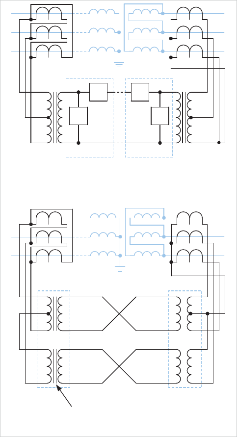
technology. The line current transformers can be connected to
a summation transformer with unequal taps, as shown in
Figure 16.25(a). This arrangement produces an output for
phase faults and also some response for
A
and
B
phase-earth
faults. However, the resulting settings will be similar to those
for phase faults and no protection will be given for
C
phase-
earth faults. An alternative technique is shown in Figure
16.25(b).
The
B
phase is taken through a separate winding on another
transformer or relay electromagnet, to provide another
balancing system. The two transformers are interconnected
with their counterparts at the other end of the feeder-
transformer by four pilot wires. Operation with three pilot
cores is possible but four are preferable, involving little increase
in pilot cost.
16.17 INTERTRIPPING
To ensure that both the high and low voltage circuit breakers
operate for faults within the transformer and feeder, it is
necessary to operate both circuit breakers from protection
normally associated with one. The technique for doing this is
known as intertripping.
The necessity for intertripping on transformer-feeders arises
from the fact that certain types of fault produce insufficient
current to operate the protection associated with one of the
circuit breakers. These faults are:
x faults in the transformer that operate the Buchholz
relay and trip the local low voltage circuit breaker, while
failing to produce enough fault current to
operate the
protection associated with the remote high voltage
circuit breaker
(b) Balanced voltage system
A
B
C
Relay electromagnets
(bias inherent)
Pilots
(a) Circulating current system
E
DD
E
A
B
C
Differential relays
Feeder
D
E
Bias winding
Operating winding
Figure 16.25: Methods of protection for transformer-feeders using
electromechanical static technology
x earth faults on the star winding of the transformer,
which, because of the position of the fault in the
winding, again produce insufficient current for relay
operation at the remote circuit breaker
x earth faults on the feeder or high voltage delta-
connected winding which trip the high voltage circuit
breaker only, leaving the transformer energised form
the low voltage side and with two high voltage phases
at near line-to-line voltage
above earth. Intermittent
arcing may follow and there is a possibility of transient
overvoltage occurring and causing a further breakdown
of insulation
Several methods are available for intertripping; these are
discussed in Chapter 8.
© 2011 Alstom Grid. Single copies of this document may be filed or printed for personal non-commercial use and must include this
copyright notice but may not be copied or displayed for commercial purposes without the prior written permission of Alstom Grid.
Chapter 16 Transformer and Transformer Feeder Protection
16-19
16.17.1 Neutral Displacement
An alternative to intertripping is to detect the condition by
measuring the residual voltage on the feeder. An earth fault
occurring on the feeder connected to an unearthed transformer
winding should be cleared by the feeder circuit, but if there is
also a source of supply on the secondary side of the
transformer, the feeder may be still live. The feeder will then
be a local unearthed system, and, if the earth fault continues in
an arcing condition, dangerous overvoltages may occur.
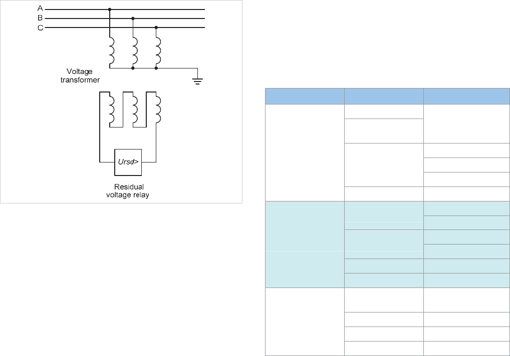
A voltage relay is energised from the broken-delta connected
secondary winding of a voltage transformer on the high
voltage line, and receives an input proportional to the zero
sequence voltage of the line, that is, to any displacement of the
neutral point; see Figure 16.26.
The relay normally receives zero voltage, but, in the presence
of an earth fault, the broken-delta voltage will rise to three
times the phase voltage. Earth faults elsewhere in the system
may also result in displacement of the neutral and hence
discrimination is achieved using definite or inverse time
characteristics.
Figure 16.26: Neutral displacement detection using voltage
transformer.
16.18 CONDITION MONITORING OF
TRANSFORMERS
It is possible to provide transformers with measuring devices to
detect early signs of degradation in various components and
provide warning to the operator to avoid a lengthy and
expensive outage due to failure. The technique, which can be
applied to other plant as well as transformers, is called
condition monitoring
, as the intent is to provide the operator
with regular information on the condition of the transformer.
By reviewing the trends in the information provided, the
operator can make a better judgement as to the frequency of
maintenance, and detect early signs of deterioration that, if
ignored, would lead to an internal fault occurring. Such
techniques are an enhancement to, but are not a replacement
for, the protection applied to a transformer.
The extent to which condition monitoring is applied to
transformers on a system will depend on many factors,
amongst which will be the policy of the asset owner, the
suitability of the design (existing transformers may require
modifications involving a period out of service – this may be
costly and not justified), the importance of the asset to system
operation, and the general record of reliability. Therefore, it
should not be expected that all transformers would be, or need
to be, so fitted.
A typical condition monitoring system for an oil-immersed
transformer is capable of monitoring the condition of various
transformer components as shown in Table 16.4. There can
be some overlap with the measurements available from a
digital/numerical relay. By the use of software to store and
perform trend analysis of the measured data, the operator can
be presented with information on the state of health of the
transformer, and alarms raised when measured values exceed
appropriate limits. This will normally provide the operator with
early warning of degradation within one or more components
of the transformer, enabling maintenance to be scheduled to
correct the problem prior to failure occurring. The
maintenance can obviously be planned to suit system
conditions, provided the rate of degradation is not excessive.
Monitored Equipment Measured Quantity Health Information
Voltage
Partial discharge measurement
(wideband voltage)
Insulation quality
Loading
Permissible overload rating
Load current
Hot-spot temperature
Bushings
Oil pressure Insulation quality
Hot-spot temperature
Oil temperature
Permissible overload rating
Oil quality
Gas-in-oil content
Winding insulation condition
Moisture-in-oil content Oil quality
Tank
Buchholz gas content Winding insulation condition
Position
Frequency of use of each tap
position
Drive power consumption OLTC health
Total switched load current OLTC contact wear
Tap changer
OLTC oil temperature OLTC health
© 2011 Alstom Grid. Single copies of this document may be filed or printed for personal non-commercial use and must include this
copyright notice but may not be copied or displayed for commercial purposes without the prior written permission of Alstom Grid.
Network Protection & Automation Guide
16-20
Monitored Equipment Measured Quantity Health Information
Oil temperature difference
Cooling air temperature
Ambient temperature
Cooler efficiency
Coolers
Pump status Cooling plant health
Conservator Oil level Tank integrity
Table 16.4: Condition monitoring for transformers
As asset owners become more conscious of the costs of an
unplanned outage, and electric supply networks are utilised
closer to capacity for long periods of time, the usefulness of
this technique can be expected to grow. See Section 16.20 for
further information on this topic
.
16.19 EXAMPLES OF TRANSFORMER
PROTECTION
This section provides three examples of the application of
modern relays to transformer protection. The latest MiCOM
P640 series relay provides advanced software to simplify the
calculations, so an earlier Alstom type KBCH relay is used to
show the complexity of the required calculations.
16.19.1 Provision of Vector Group Compensation and
Zero-Sequence Filtering
Figure 16.27 shows a delta-star transformer to be protected
using a unit protection scheme. With a main winding
connection of Dyn11, suitable choices of primary and
secondary CT winding arrangements, and software phase
compensation are to be made. With the KBCH relay, phase
compensation is selected by the user in the form of software-
implemented ICTs.
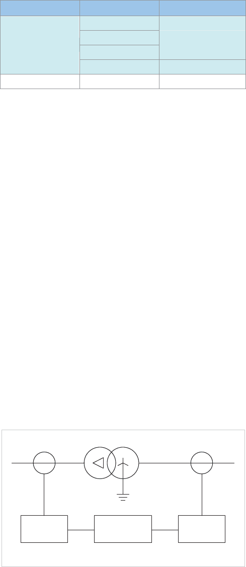
Unit Protection
Relay
Secondary
ICTs
Primary
ICTs
Secondary CTsPrimary CTs
Dyn 11
I
d
>
Figure 16.27: Transformer zero sequence filtering example
With the Dyn11 connection, the secondary voltages and
currents are displaced by +30
o
from the primary. Therefore,
the combination of primary, secondary and phase correction
must provide a phase shift of –30
o
of the secondary quantities
relative to the primary.
For simplicity, the CTs on the primary and secondary windings
of the transformer are connected in star. The required phase
shift can be achieved either by use of ICT connections on the
primary side having a phase shift of +30
o
or on the secondary
side having a phase shift of –30
o
. There is a wide combination
of primary and secondary ICT winding arrangements that can
provide this, such as
Yd10
(+60
o
) on the primary and
Yd3
(-
90
o
) on the secondary. Another possibility is
Yd11
(+30
o
) on
the primary and
Yy0
(0
o
) on the secondary. It is usual to
choose the simplest arrangements possible, and therefore the
latter of the above two possibilities might be selected.
However, the distribution of current in the primary and
secondary windings of the transformer due to an external earth
fault on the secondary side of the transformer must now be
considered. The transformer has an earth connection on the
secondary winding, so it can deliver zero sequence current to
the fault. Use of star connected main CTs and
Yy0
connected
ICTs provides a path for the zero sequence current to reach the
protection relay. On the primary side of the transformer, the
delta connected main primary winding causes zero-sequence
current to circulate round the delta and hence will not be seen
by the primary side main CTs. The protection relay will
therefore not see any zero-sequence current on the primary
side, and hence detects the secondary side zero sequence
current incorrectly as an in-zone fault.
The solution is to provide the ICTs on the secondary side of the
transformer with a delta winding, so that the zero-sequence
current circulates round the delta and is not seen by the relay.
Therefore, a rule can be developed that a transformer winding
with a connection to earth must have a delta-connected main
or ICT for unit protection to operate correctly.
Selection of
Yy0
connection for the primary side ICTs and
Yd1
(–30
o
) for the secondary side ICTs provides the required phase
shift and the zero-sequence trap on the secondary side.
Modern numerical MiCOM relays employ a setting wizard,
needing only vector group and zero sequence data to be
entered. The relay then automatically adapts itself to suit the
application.
16.19.2 Unit Protection of a Delta-Star Transformer
Figure 16.28 shows a delta-star transformer to which unit
protection is to be applied, including restricted earth fault
protection to the star winding.
Referring to the figure, the ICTs have already been correctly
selected, and are conveniently applied in software. It therefore
remains to calculate suitable ratio compensation (it is assumed
that the transformer has no taps), transformer differential
protection settings and restricted earth fault settings.
© 2011 Alstom Grid. Single copies of this document may be filed or printed for personal non-commercial use and must include this
copyright notice but may not be copied or displayed for commercial purposes without the prior written permission of Alstom Grid.
