ALSTOM T&D. Network Protection And Automation Guide (NPAG)
Подождите немного. Документ загружается.

Alstom Grid 16-1
Chapter 16
Transformer and Transformer Feeder
Protection
16.1 Introduction
16.2 Winding Faults
16.3 Magnetising Inrush
16.4 Transformer Overheating
16.5 Transformer Protection – Overview
16.6 Transformer Overcurrent Protection
16.7 Restricted Earth Fault Protection
16.8 Differential Protection
16.9 Differential Protection Stabilisation During
Magnetising Inrush Conditions
16.10 Combined Differential and Restricted Earth
Fault Schemes
16.11 Earthing Transformer Protection
16.12
Autotransformer Protection
16.13 Overfluxing Protection
16.14 Tank-Earth Protection
16.15 Oil and Gas Devices
16.16 Transformer-Feeder Protection
16.17 Intertripping
16.18 Condition Monitoring of Transformers
16.19 Examples of Transformer Protection
16.20 Transformer Asset Management
16.1 INTRODUCTION
The development of modern power systems has been reflected
in the advances in transformer design. This has resulted in a
wide range of transformers with sizes ranging from a few kVA
to several hundred MVA being available for use in a wide
variety of applications.
The considerations for a transformer protection package vary
with the application and importance of the transformer. To
reduce the effects of thermal stress and electrodynamic forces,
it is advisable to ensure that the protection package used
minimises the time for disconnection in the event of a fault
occurring within the transformer. Small distribution
transformers can be protected satisfactorily, from both
technical and economic considerations, by the use of fuses or
overcurrent relays. This results in time-delayed protection due
to downstream co-ordination requirements. However, time-
delayed fault clearance is unacceptable on larger power
transformers used in distribution, transmission and generator
applications, due to system operation/stability and cost of
repair/length of outage considerations.
Transformer faults are generally classified into five categories:
x winding and terminal faults
x core faults
x tank and transformer accessory faults
x on–load tap changer faults
x abnormal operating conditions
x sustained or uncleared external faults
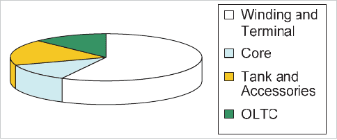
For faults originating in the transformer itself, the approximate
proportion of faults due
to each of the causes listed above is
shown in Figure 16.1.
Figure 16.1: Transformer fault statistics
16.2 WINDING FAULTS
A fault on a transformer winding is controlled in magnitude by
the following factors:
© 2011 Alstom Grid. Single copies of this document may be filed or printed for personal non-commercial use and must include this
copyright notice but may not be copied or displayed for commercial purposes without the prior written permission of Alstom Grid.
Network Protection & Automation Guide
16-2
x source impedance
x neutral earthing impedance
x transformer leakage reactance
x fault voltage
x winding connection
Several distinct cases arise and are examined below.
16.2.1 Star-Connected Winding with Neutral Point
Earthed Through an Impedance
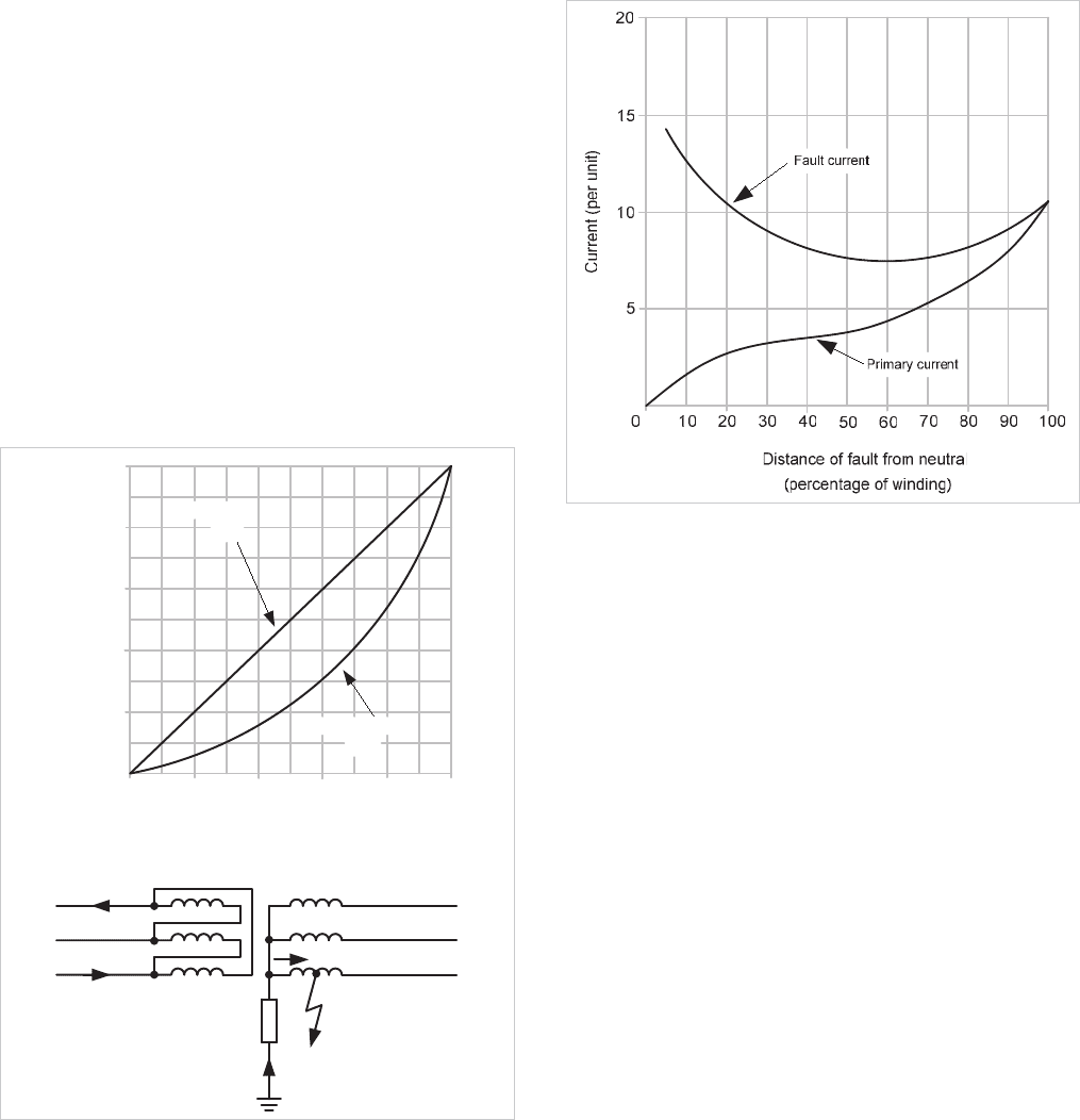
The winding earth fault current depends on the earthing
impedance value and is also proportional to the distance of the
fault from the neutral point, since the fault voltage will be
directly proportional to this distance.
For a fault on a transformer secondary winding, the
corresponding primary current will depend on the
transformation ratio between the primary winding and the
short-circuited secondary turns. This also varies with the
position of the fault, so that the fault current in the transformer
primary winding is proportional to the square of the fraction of
the winding that is short-circuited. The effect is shown in
Figure 16.2. Faults in the lower third of the winding produce
very little current in the primary winding, making fault
detection by primary current measurement difficult.
20
200
10
10 4030
50
60
50
30
40
90
80
70
100
60
90
70
80
100
Primary Current
Fault current
I
F
I
p
(I
F
)
(percentage of winding)
Distance of fault from Neutral
Percentage of respective maximum
Single-Phase Earth fault current
(I
p
)
Figure 16.2: Earth fault current in resistance-earthed star winding
16.2.2 Star-Connected Winding with Neutral Point
Solidly Earthed
The fault current is controlled mainly by the leakage reactance
of the winding, which varies in a complex manner with the
position of the fault. The variable fault point voltage is also an
important factor, as in the case of impedance earthing. For
faults close to the neutral end of the winding, the reactance is
very low, and results in the highest fault currents. The
variation of current with fault position is shown in Figure 16.3.
Figure 16.3: Earth fault current in solidly earthed star winding
For secondary winding faults, the primary winding fault
current is determined by the variable transformation ratio; as
the secondary fault current magnitude stays high throughout
the winding, the primary fault current is large for most points
along the winding.
16.2.3 Delta-Connected Winding
No part of a delta-connected winding operates with a voltage
to earth of less than 50% of the phase voltage. The range of
fault current magnitude is therefore less than for a star
winding. The actual value of fault current will still depend on
the method of system earthing; it should also be remembered
that the impedance of a delta winding is particularly high to
fault currents flowing to a centrally placed fault on one leg.
The impedance can be expected to be between 25% and 50%,
based on the transformer rating, regardless of the normal
balanced through-current impedance. As the prefault voltage
to earth at this point is half the normal phase voltage, the
earth fault current may be no more than the rated current, or
even less than this value if the source or system earthing
impedance is appreciable. The current will flow to the fault
from each side through the two half windings, and will be
© 2011 Alstom Grid. Single copies of this document may be filed or printed for personal non-commercial use and must include this
copyright notice but may not be copied or displayed for commercial purposes without the prior written permission of Alstom Grid.
Chapter 16 Transformer and Transformer Feeder Protection
16-3
divided between two phases of the system. The individual
phase currents may therefore be relatively low, resulting in
difficulties in providing protection.
16.2.4 Phase to Phase Faults
Faults between phases within a transformer are relatively rare;
if such a fault does occur it will give rise to a substantial
current comparable to the earth fault currents discussed in
Section 16.2.2.
16.2.5 Interturn Faults
In low voltage transformers, interturn insulation breakdown is
unlikely to occur unless the mechanical force on the winding
due to external short circuits has caused insulation
degradation, or insulating oil (if used) has become
contaminated by moisture.
A high voltage transformer connected to an overhead
transmission system will be subjected to steep fronted impulse
voltages, arising from lightning strikes, faults and switching
operations. A line surge, which may be of several times the
rated system voltage, will concentrate on the end turns of the
winding because of the high equivalent frequency of the surge
front. Part-winding resonance, involving voltages up to 20
times rated voltage may occur. The interturn insulation of the
end turns is reinforced, but cannot be increased in proportion
to the insulation to earth, which is relatively great. Partial
winding flashover is therefore more likely. The subsequent
progress of the fault, if not detected in the earliest stage, may
well destroy the evidence of the true cause.
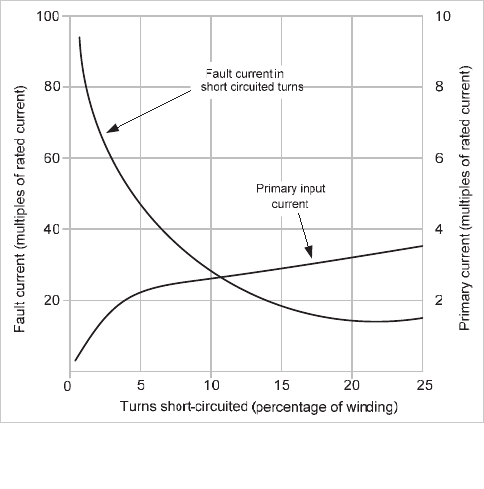
A short circuit of a few turns of the winding will give rise to a
heavy fault current in the short-circuited loop, but the terminal
currents will be very small, because of the high ratio of
transformation between the whole winding and the short-
circuited turns.
The graph in Figure 16.4 shows the corresponding data for a
typical transformer of 3.25% impedance with the short-
circuited turns symmetrically located in the centre of the
winding.
16.2.6 Core Faults
A conducting bridge across the laminated structures of the
core can permit sufficient eddy-current to flow to cause serious
overheating. The bolts that clamp the core together are always
insulated to avoid this trouble. If any portion of the core
insulation becomes defective, the resultant heating may reach
a magnitude sufficient to damage the winding.
Figure 16.4: Interturn fault current/number of turns short-circuited
The additional core loss, although causing severe local heating,
does not produce a noticeable change in input current and
could not be detected by the normal electrical protection.
However it is important that the condition is detected before a
major fault has been created. In an oil-immersed transformer,
core heating sufficient to cause winding insulation damage
also causes breakdown of some of the oil with an
accompanying evolution of gas. This gas escapes to the
conservator and is used to operate a mechanical relay; see
Section 16.15.3.
16.2.7 Tank Faults
Loss of oil through tank leaks ultimately produces a dangerous
condition, either because of a reduction in winding insulation
or because of overheating on load due to the loss of cooling.
Overheating may also occur due to prolonged overloading,
blocked cooling ducts due to oil sludging or failure of the forced
cooling system, if fitted.
16.2.8 Externally Applied Conditions
Sources of abnormal stress in a transformer are:
x overload
x system faults
x overvoltage
x reduced system frequency
16.2.8.1 Overload
Overload causes increased 'copper loss' and a consequent
temperature rise. Overloads can be carried for limited periods
and recommendations for oil-immersed transformers are given
in IEC 60354.
© 2011 Alstom Grid. Single copies of this document may be filed or printed for personal non-commercial use and must include this
copyright notice but may not be copied or displayed for commercial purposes without the prior written permission of Alstom Grid.

Network Protection & Automation Guide
16-4
The thermal time constant of naturally cooled transformers lies
between 2.5-5 hours. Shorter time constants apply in the case
of force-cooled transformers.
16.2.8.2 System faults
System short circuits produce a relatively intense rate of
heating of the feeding transformers, the copper loss increasing
in proportion to the square of the per unit fault current. The
typical duration of external short circuits that a transformer
can sustain without damage if the current is limited only by the
self-reactance is shown in Table 16.1. IEC 60076 provides
further guidance on short-circuit withstand levels.
Transformer Reactance
(%)
Fault Current
(Multiple of Rating)
Permitted Fault
Duration (seconds)
4 25 2
5 20 2
6 16.6 2
7 14.2 2
Table 16.1: Transformer fault current withstand data
Maximum mechanical stress on windings occurs during the
first cycle of the fault. Avoidance of damage is a matter of
transformer design.
16.2.8.3 Overvoltages
Overvoltage conditions are of two kinds:
x transient surge voltages
x power frequency overvoltage
Transient overvoltages arise from faults, switching, and
lightning disturbances and are liable to cause interturn faults,
as described in Section 16.
2.5. These overvoltages are usually
limited by shunting the high voltage terminals to earth either
with a plain rod gap or by surge diverters, which comprise a
stack of short gaps in series with a non-linear resistor. The
surge diverter, in contrast to the rod gap, has the advantage of
extinguishing the flow of power current after discharging a
surge, in this way avoiding subsequent isolation of the
transformer.
Power frequency overvoltage causes both an increase in stress
on the insulation and a proportionate increase in the working
flux. The latter effect causes an increase in the iron loss and a
disproportionately large increase in magnetising current. In
addition, flux is diverted from the laminated core into
structural steel parts. The core bolts, which normally carry
little flux, may be subjected to a large flux diverted from the
highly saturated region of core alongside. This leads to a rapid
temperature rise in the bolts, destroying their insulation and
damaging coil insulation if the condition continues.
16.2.8.4 Reduced system frequency
Reduction of system frequency has an effect with regard to flux
density, similar to that of overvoltage.
It follows that a transformer can operate with some degree of
overvoltage with a corresponding increase in frequency, but
operation must not be continued with a high voltage input at a
low frequency. Operation cannot be sustained when the ratio
of voltage to frequency, with these quantities given values in
per unit of their rated values, exceeds unity by more than a
small amount, for instance if
V/f >1.1. If a substantial rise in
system voltage has been catered for in the design, the base of
'unit voltage' should be taken as the highest voltage for which
the transformer is designed.
16.3 MAGNETISING INRUSH
The phenomenon of magnetising inrush is a transient
condition that occurs primarily when a transformer is
energised. It is not a fault condition, and therefore transformer
protection must remain stable during the inrush transient.
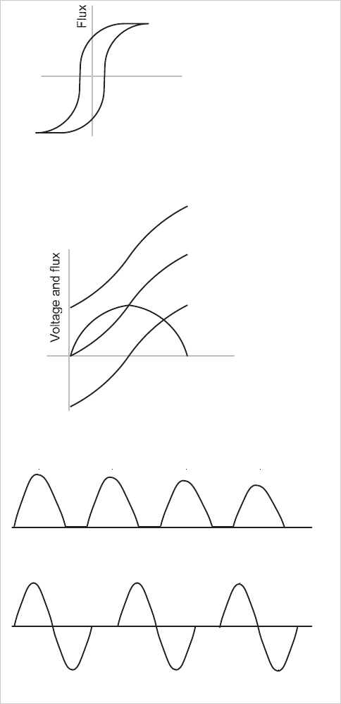
Figure 16.5(a) shows a transformer magnetising
characteristic. To minimise material costs, weight and size,
transformers are generally operated near to the ‘knee point’ of
the magnetising characteristic. Consequently, only a small
increase in core flux above normal operating levels will result in
a high magnetising current.
Under normal steady-state conditions, the magnetising current
associated with the operating flux level is relatively small
(Figure 16.5(b)). However, if a transformer winding is
energised at a voltage zero, with no remanent flux, the flux
level during the first voltage cycle (2 x normal flux) will result
in core saturation and a high non-sinusoidal magnetising
current waveform – see Figure 16.5(c). This current is
referred to as magnetising inrush current and may persist for
several cycles.
Several factors affect the magnitude and duration of the
magnetising current inrush:
x residual flux – worst-case conditions result in the flux
peak value attaining 280% of normal value
x point on wave switching
x number of banked transforme
rs
x transformer design and rating
x system fault level
© 2011 Alstom Grid. Single copies of this document may be filed or printed for personal non-commercial use and must include this
copyright notice but may not be copied or displayed for commercial purposes without the prior written permission of Alstom Grid.
Chapter 16 Transformer and Transformer Feeder Protection
16-5
(d) Inrush without offset, due to yoke saturation
Zero
axis
Zero
axis
(c) Typical inrush current
Slow Decrement
(b) Steady and maximum offset fluxes
Transient flux
80% residual at
switching
Transient flux
at switching
no residual
Steady-state
flux
Voltage
Time
(a) Typical magnetising characteristic
current
Magnetising
Normal peak flux
Figure 16.5: Transformer magnetising inrush
The very high flux densities quoted above are so far beyond the
normal working range that the incremental relative
permeability of the core approximates to unity and the
inductance of the winding falls to a value near that of the 'air-
cored' inductance. The current wave, starting from zero,
increases slowly at first, the flux having a value just above the
residual value and the permeability of the core being
moderately high. As the flux passes the normal working value
and enters the highly saturated portion of the magnetising
characteristic, the inductance falls and the current rises rapidly
to a peak that may be 500% of the steady state magnetising
current. When the peak is passed at the next voltage zero, the
following negative half cycle of the voltage wave reduces the
flux to the starting value, the current falling symmetrically to
zero. The current wave is therefore fully offset and is only
restored to the steady state condition by the circuit losses. The
time constant of the transient has a range between 0.1 second
(for a 100kVA transformer) to 1.0 second (for a large unit). As
the magnetising characteristic is non-linear, the envelope of
the transient current is not strictly of exponential form; the
magnetising current can be observed to be still changing up to
30 minutes after switching on.
Although correct choice of the point on the wave for a single–
phase transformer will result in no transient inrush, mutual
effects ensure that a transient inrush occurs in all phases for
three-phase transformers.
16.3.1 Harmonic Content of Inrush Waveform
The waveform of transformer magnetising current contains a
proportion of harmonics that increases as the peak flux density
is raised to the saturating condition. The magnetising current
of a transformer contains a third harmonic and progressively
smaller amounts of fifth and higher harmonics. If the degree
of saturation is progressively increased, not only will the
harmonic content increase as a whole, but the relative
proportion of fifth harmonic will increase and eventually
exceed the third harmonic. At a still higher level the seventh
would overtake the fifth harmonic but this involves a degree of
saturation that will not be experienced with power
transformers.
The energising conditions that result in an offset inrush current
produce a waveform that is asymmetrical. Such a wave
typically contains both even and odd harmonics. Typical
inrush currents contain substantial amounts of second and
third harmonics and diminishing amounts of higher orders. As
with the steady state wave, the proportion of harmonics varies
with the degree of saturation, so that as a severe inrush
transient decays, the harmonic makeup of the current passes
through a range of conditions.
16.4 TRANSFORMER OVERHEATING
The rating of a transformer is based on the temperature rise
above an assumed maximum ambient temperature; under this
condition no sustained overload is usually permissible. At a
lower ambient temperature some degree of sustained overload
can be safely applied. Short-term overloads are also
permissible to an extent dependent on the previous loading
conditions. IEC 60354 provides guidance in this respect.
The only certain statement is that the winding must not
overheat; a temperature of about
95°C is considered to be the
normal maximum working value beyond which a further rise of
© 2011 Alstom Grid. Single copies of this document may be filed or printed for personal non-commercial use and must include this
copyright notice but may not be copied or displayed for commercial purposes without the prior written permission of Alstom Grid.
Network Protection & Automation Guide
16-6
8°- 10°C, if sustained, will halve the insulation life of the unit.
Protection against overload is therefore based on winding
temperature, which is usually measured by a thermal image
technique. Protection is arranged to trip the transformer if
excessive temperature is reached. The trip signal is usually
routed via a digital input of a protection relay on one side of
the transformer, with both alarm and trip facilities made
available through programmable logic in the relay.
Intertripping between the relays on the two sides of the
transformer is usually applied to ensure total disconnection of
the transformer.
Winding temperature protection may be included as a part of a
complete monitoring package. See Section 16.18 for more
details.
16.5 TRANSFORMER PROTECTION –
OVERVIEW
The problems relating to transformers described in Section
16.4 require some means of protection. Table 16.2
summarises the problems and the possible forms of protection
that may be used. The following sections provide more detail
on the individual protection methods. It is normal for a
modern relay to provide all of the required protection functions
in a single package, in contrast to electromechanical types that
would require several relays complete with interconnections
and higher overall CT burdens.
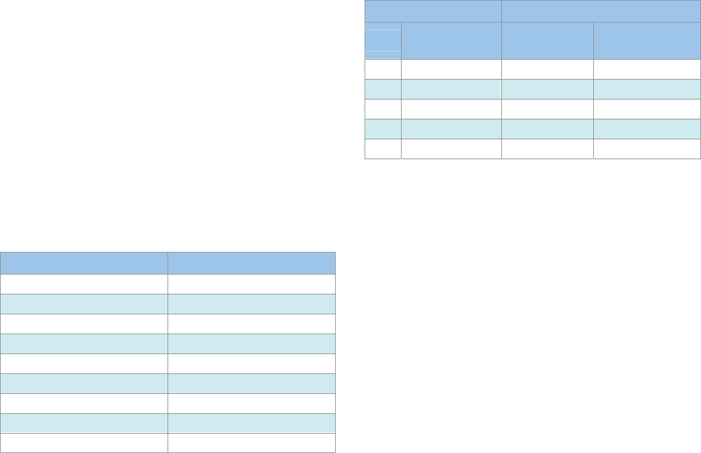
Fault Type Protection Used
Primary winding Phase-phase fault Differential; Overcurrent
Primary winding Phase-earth fault Differential; Overcurrent
Secondary winding Phase-phase fault Differential
Secondary winding Phase-earth fault Differential; Restricted Earth Fault
Interturn Fault Differential, Buchholz
Core Fault Differential, Buchholz
Tank Fault Differential, Buchholz; Tank-Earth
Overfluxing Overfluxing
Overheating Thermal
Table 16.2: Transformer fault types/protection methods
16.6 TRANSFORMER OVERCURRENT
PROTECTION
Fuses may adequately protect small transformers, but larger
ones require overcurrent protection using a relay and CB, as
fuses do not have the required fault breaking capacity.
16.6.1 Fuses
Fuses commonly protect small distribution transformers
typically up to ratings of 1MVA at distribution voltages. In
many cases no circuit breaker is provided, making fuse
protection the only available means of automatic isolation.
The fuse must have a rating well above the maximum
transformer load current to withstand the short duration
overloads that may occur. Also, the fuses must withstand the
magnetising inrush currents drawn when power transformers
are energised. High Rupturing Capacity (HRC) fuses, although
very fast in operation with large fault currents, are extremely
slow with currents of less than three times their rated value. It
follows that such fuses will do little to protect the transformer,
serving only to protect the system by disconnecting a faulty
transformer after the fault has reached an advanced stage.
Table 16.3 shows typical ratings of fuses for use with 11kV
transformers
Transformer Rating Fuse
kVA
Full Load Current
(A)
Rated Current
(A)
Operating Time at 3 x
Rating (s)
100 5.25 16 3.0
200 10.5 25 3.0
315 15.8 36 10.0
500 26.2 50 20.0
1000 52.5 90 30.0
Table 16.3: Typical fuse ratings for use with distribution transformers
This table should be taken only as a typical example;
considerable differences exist in the time characteristics of
different types of HRC fuses. Furthermore grading with
protection on the secondary side has not been considered.
16.6.2 Overcurrent Relays
With the advent of ring main units incorporating SF
6
circuit
breakers and isolators, protection of distribution transformers
can now be provided by overcurrent trips (e.g. tripping
controlled by time limit fuses connected across the secondary
windings of in-built current transformers) or by relays
connected to current transformers located on the transformer
primary side. Overcurrent relays are also used on larger
transformers provided with standard circuit breaker control.
Improvement in protection is obtained in two ways; the
excessive delays of the HRC fuse for lower fault currents are
avoided and an earth-fault tripping element is provided in
addition to the overcurrent feature.
The time delay characteristic should be chosen to discriminate
with circuit protection on the secondary side. A high-set
instantaneous relay element is often provided, the current
setting being chosen to avoid operation for a secondary short
circuit. This enables high-speed clearance of primary terminal
short circuits.
© 2011 Alstom Grid. Single copies of this document may be filed or printed for personal non-commercial use and must include this
copyright notice but may not be copied or displayed for commercial purposes without the prior written permission of Alstom Grid.

Chapter 16 Transformer and Transformer Feeder Protection
16-7
16.7 RESTRICTED EARTH FAULT PROTECTION
Conventional earth fault protection using overcurrent elements
fails to provide adequate protection for transformer windings.
This applies particularly to a star-connected winding with an
impedance-earthed neutral, as discussed in Section 16.2.1.
The degree of protection is very much improved by the
application of restricted earth fault protection (or REF
protection). This is a unit protection scheme for one winding
of the transformer. It can be a high impedance type as shown
in Figure 16.6 or a biased low-impedance type. For the high-
impedance type, the residual current of three line current
transformers is balanced against the output of a current
transformer in the neutral conductor. In the biased low-
impedance version, the three phase currents and the neutral
current become the bias inputs to a differential element.
The system is operative for faults within the region between
current transformers, that is, for faults on the star winding in
question. The system remains stable for all faults outside this
zone.
>
I
High impedance relay
Figure 16.6: Restricted earth fault protection for a star winding
The gain in protection performance comes not only from using
an instantaneous relay with a low setting, but also because the
whole fault current is measured, not merely the transformed
component in the HV primary winding (if the star winding is a
secondary winding). Hence, although the prospective current
level decreases as fault positions progressively nearer the
neutral end of the winding are considered, the square law
which controls the primary line current is not applicable, and
with a low effective setting, a large percentage of the winding
can be covered.
Restricted earth fault protection is often applied even when the
neutral is solidly earthed. Since fault current then remains at a
high value even to the last turn of the winding (Figure 16.2),
virtually complete cover for earth faults is obtained. This is an
improvement compared with the performance of systems that
do not measure the neutral conductor current.
Earth fault protection applied to a delta-connected or
unearthed star winding is inherently restricted, since no zero
sequence components can be transmitted through the
transformer to the other windings.
Both windings of a transformer can be protected separately
with restricted earth fault protection, thereby providing high-
speed protection against earth faults for the whole transformer
with relatively simple equipment. A high impedance relay is
used, giving fast operation and phase fault stability.
16.8 DIFFERENTIAL PROTECTION
The restricted earth fault schemes described above in Section
16.7 depend entirely on the Kirchhoff principle that the sum of
the currents flowing into a conducting network is zero. A
differential system can be arranged to cover the complete
transformer; this is possible because of the high efficiency of
transformer operation, and the close equivalence of ampere-
turns developed on the primary and secondary windings.
Figure 16.7 shows the principle. Current transformers on the
primary and secondary sides are connected to form a
circulating current system.
Figure 16.7: Principle of transformer differential protectio
n
16.8.1 Basic Considerations for Transformer
Differential Protection
In applying the principles of differential protection to
transformers, a variety of considerations have to be taken into
account. These include:
x correction for possible phase shift across the
transformer windings (phase correction)
x the effects of the variety of earthing and winding
arrangements
(filtering of zero sequence currents)
x correction for possible unbalance of signals from
current transformers on either side of the windings
(ratio correction)
x the effect of magnetising inrush during initial
energisation
x the possible oc
currence of overfluxing
© 2011 Alstom Grid. Single copies of this document may be filed or printed for personal non-commercial use and must include this
copyright notice but may not be copied or displayed for commercial purposes without the prior written permission of Alstom Grid.
Network Protection & Automation Guide
16-8
In traditional transformer differential schemes, the
requirements for phase and ratio correction were met by the
application of external interposing current transformers (ICTs),
as a secondary replica of the main winding connections, or by
a delta connection of the main CTs to provide phase correction
only. Digital/numerical relays implement ratio and phase
correction in the relay software instead, thus enabling most
combinations of transformer winding arrangements to be
catered for, irrespective of the winding connections of the
primary CTs. This avoids the additional space and cost
requirements of hardware interposing CTs.
16.8.2 Line Current Transformer Primary Ratings
Line current transformers have primary ratings selected to be
approximately equal to the rated currents of the transformer
windings to which they are applied. Primary ratings will
usually be limited to those of available standard ratio CTs.
16.8.3 Phase Correction
Correct operation of transformer differential protection requires
that the transformer primary and secondary currents, as
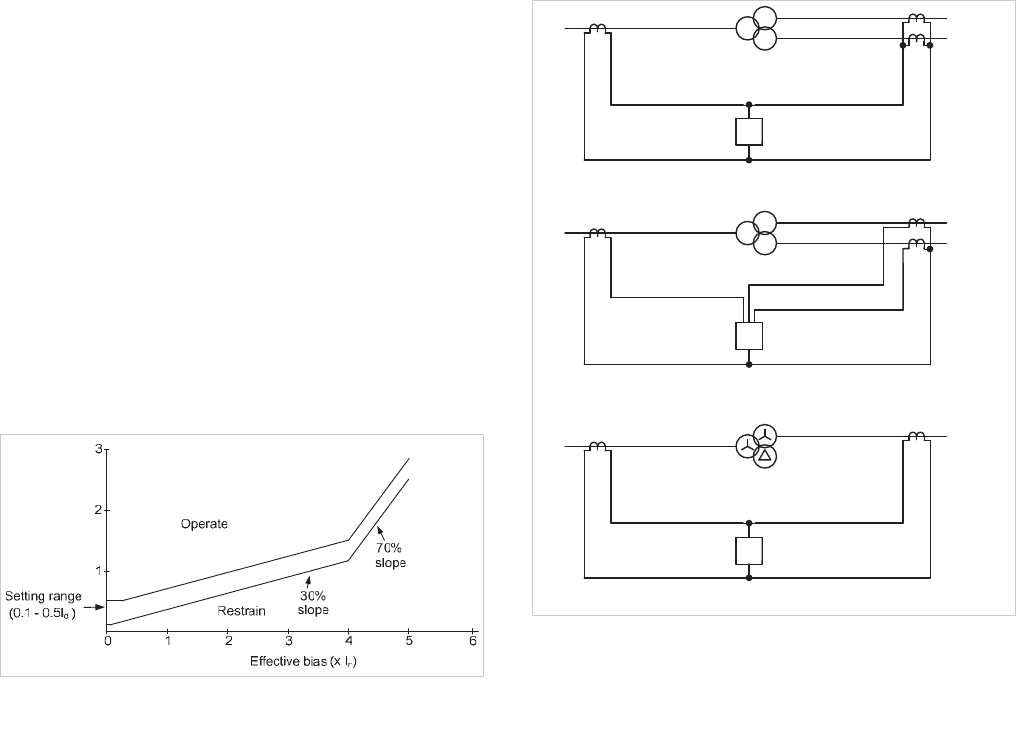
measured by the relay, are in phase. If the transformer is
connected delta/star, as shown in Figure 16.8, balanced three-
phase through current suffers a phase change of 30°. If left
uncorrected, this phase difference would lead to the relay
seeing through current as an unbalanced fault current, and
result in relay operation. Phase correction must be
implemented.
C
A
B
I
d
>
I
d
> I
d
>
Figure 16.8: Differential protection for two-winding delta/star
transformer
Electromechanical and static relays use appropriate CT/ICT
connections to ensure that the primary and secondary currents
applied to the relay are in phase.
For digital and numerical relays, it is common to use star-
connected line CTs on all windings of the transformer and
compensate for the winding phase shift in software.
Depending on relay design, the only data required in such
circumstances may be the transformer vector group
designation. Phase compensation is then performed
automatically. Caution is required if such a relay is used to
replace an existing electromechanical or static relay, as the
primary and secondary line CTs may not have the same
winding configuration. Phase compensation and associated
relay data entry requires more detailed consideration in such
circumstances. Rarely, the available phase compensation
facilities cannot accommodate the transformer winding
connection, and in such cases interposing CTs must be used.
16.8.4 Filtering of Zero Sequence Currents
As described in Chapter 10.8, it is essential to provide some
form of zero sequence filtering where a transformer winding
can pass zero sequence current to an external earth fault. This
is to ensure that out-of-zone earth faults are not seen by the
transformer protection as an in-zone fault. This is achieved by
use of delta-connected line CTs or interposing CTs for older
relays, and hence the winding connection of the line and/or
interposing CTs must take this into account, in addition to any
phase compensation necessary. For digital/numerical relays,
the required filtering is applied in the relay software. Table
16.4 summarises the phase compensation and zero sequence
filtering requirements. An example of an incorrect choice of
ICT connection is given in Section 16.19.1.
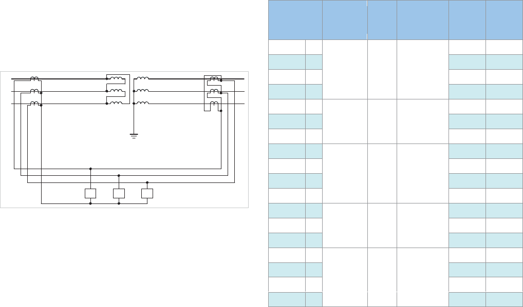
Table 16.4: Current transformer connections for power transformers of
various vector groups
Transformer
Connection
Transformer
Phase Shift
Clock
Face
Vector
Phase
Compensation
Required
HV Zero
Sequence
Filtering
LV Zero
Sequence
Filtering
Yy0 Yes Yes
Zd0 Yes
Dz0 Yes
Dd0
0° 0 0°
Yz1 Zy1 Yes Yes
Yd1 Yes
Dy1
-30° 1 30°
Yes
Yy6 Yes Yes
Zd6 Yes
Dz6 Yes
Dd6
-180° 1 180°
Yz11 Zy11 Yes Yes
Yd11 Yes
Dy11
30° 11 -30°
Yes
YyH YzH Yes Yes
YdH ZdH Yes
DzH DyH Yes
DdH
(H / 12) x 360° Hour ‘H’ -(H / 12) x 360°
© 2011 Alstom Grid. Single copies of this document may be filed or printed for personal non-commercial use and must include this
copyright notice but may not be copied or displayed for commercial purposes without the prior written permission of Alstom Grid.
Chapter 16 Transformer and Transformer Feeder Protection
16-9
16.8.5 Ratio Correction
Correct operation of the differential element requires that
currents in the differential element balance under load and
through fault conditions. As the primary and secondary line CT
ratios may not exactly match the transformer rated winding
currents, digital/numerical relays are provided with ratio
correction factors for each of the CT inputs. The correction
factors may be calculated automatically by the relay from
knowledge of the line CT ratios and the transformer MVA
rating. However, if interposing CTs are used, ratio correction
may not be such an easy task and may need to take into
account a factor of
3 if delta-connected CTs or ICTs are
involved. If the transformer is fitted with a tap changer, line
CT ratios and correction factors are normally chosen to achieve
current balance at the mid tap of the transformer. It is
necessary to ensure that current mismatch due to off-nominal
tap operation will not cause spurious operation.
The example in Section 16.19.2 shows how ratio correction
factors are used, and that of Section 16.19.3 shows how to set
the ratio correction factors for a transformer with an
unsymmetrical tap range.
16.8.6 Bias Setting
Bias is applied to transformer differential protection for the
same reasons as any unit protection scheme – to ensure
stability for external faults while allowing sensitive settings to
pick up internal faults. The situation is slightly complicated if a
tap changer is present. With line CT/ICT ratios and correction
factors set to achieve current balance at nominal tap, an off-
nominal tap may be seen by the differential protection as an
internal fault. By selecting the minimum bias to be greater
than sum of the maximum tap of the transformer and possible
CT errors, maloperation due to this cause is avoided. Some
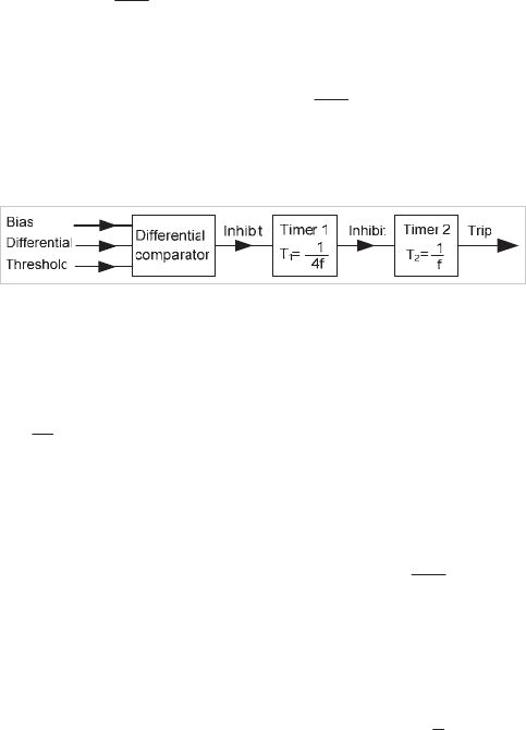
relays use a bias characteristic with three sections, as shown in
Figure 16.9. The first section is set higher than the
transformer magnetising current. The second section is set to
allow for off-nominal tap settings, while the third has a larger
bias slope beginning well above rated current to cater for
heavy through-fault conditions.
Differential current ( I
d
)
Figure 16.9: Typical bias characteristic
16.8.7 Transformers with Multiple Windings
The unit protection principle remains valid for a system having
more than two connections, so a transformer with three or
more windings can still be protected by the application of the
above principles.
When the power transformer has only one of its three
windings connected to a source of supply, with the other two
windings feeding loads, a relay with only two sets of CT inputs
can be used, connected as shown in Figure 16.10(a). The
separate load currents are summated in the CT secondary
circuits, and will balance with the infeed current on the supply
side.
When more than one source of fault current infeed exists,
there is a danger in the scheme of Figure 16.10(a) of current
circulating between the two paralleled sets of current
transformers without producing any bias. It is therefore
important a relay is used with separate CT inputs for the two
secondaries - Figure 16.10(b).
When the third winding consists of a delta-connected tertiary
with no connections brought out, the transformer may be
regarded as a two winding transformer for protection purposes
and protected as shown in Figure 16.10(c).
Source
Source
Loads
Source
(c) Three winding transformer with unloaded delta tertiary
(b) Three winding transformer (three power sources)
(a) Three winding transformer (one power source)
I
d
>
I
d
>
I
d
>
Possible
fault
infeed
Possible
fault
infeed
Figure 16.10: Differential protection arrangements for three-winding
transformers (shown single phase for simplicity)
© 2011 Alstom Grid. Single copies of this document may be filed or printed for personal non-commercial use and must include this
copyright notice but may not be copied or displayed for commercial purposes without the prior written permission of Alstom Grid.
Network Protection & Automation Guide
16-10
16.9 DIFFERENTIAL PROTECTION
STABILISATION DURING MAGNETISING
INRUSH CONDITIONS
The magnetising inrush phenomenon described in Section
16.3 produces current input to the energised winding which
has no equivalent on the other windings. The whole of the
inrush current appears, therefore, as unbalance and the
differential protection is unable to distinguish it from current
due to an internal fault. The bias setting is not effective and an
increase in the protection setting to a value that would avoid
operation would make the protection of little value. Methods
of delaying, restraining or blocking of the differential element
must therefore be used to prevent mal-operation of the
protection.
16.9.1 Time Delay
Since the phenomenon is transient, stability can be maintained
by providing a small time delay. However, because this time
delay also delays operation of the relay in the event of a fault
occurring at switch-on, the method is no longer used.
16.9.2 Harmonic Restraint
The inrush current, although generally resembling an in-zone
fault current, differs greatly when the waveforms are
compared. The difference in the waveforms can be used to
distinguish between the conditions.
As stated before, the inrush current contains all harmonic
orders, but these are not all equally suitable for providing bias.
In practice, only the second harmonic is used.
This component is present in all inrush waveforms. It is typical
of waveforms in which successive half period portions do not
repeat with reversal of polarity but in which mirror-image
symmetry can be found about certain ordinates.
The proportion of second harmonic varies somewhat with the
degree of saturation of the core, but is always present as long
as the uni-directional component of flux exists. The amount
varies according to factors in the transformer design. Normal
fault currents do not contain second or other even harmonics,
nor do distorted currents flowing in saturated iron cored coils
under steady state conditions.
The output current of a current transformer that is energised
into steady state saturation will contain odd harmonics but not
even harmonics. However, should the current transformer be
saturated by the transient component of the fault current, the
resulting saturation is not symmetrical and even harmonics are
introduced into the output current. This can have the
advantage of improving the through fault stability performance
of a differential relay.
The second harmonic is therefore an attractive basis for a
stabilising bias against inrush effects, but care must be taken
to ensure that the current transformers are sufficiently large so
that the harmonics produced by transient saturation do not
delay normal operation of the relay. The differential current is
passed through a filter that extracts the second harmonic; this
component is then applied to produce a restraining quantity
sufficient to overcome the operating tendency due to the whole
of the inrush current that flows in the operating circuit. By this
means a sensitive and high-speed system can be obtained.
16.9.3 Inrush Detection Blocking – Gap Detection
Technique
Another feature that characterises an inrush current can be
seen from Figure 16.5 where the two waveforms (c) and (d)
have periods in the cycle where the current is zero. The
minimum duration of this zero period is theoretically one
quarter of the cycle and is easily detected by a simple timer T1
that is set to
f4
1
seconds. Figure 16.11 shows the circuit in
block diagram form. Timer T1 produces an output only if the
current is zero for a time exceeding
f4
1
seconds. It is reset
when the instantaneous value of the differential current
exceeds the setting reference.
Figure 16.11: Block diagram to show waveform gap-detecting
principle
As the zero in the inrush current occurs towards the end of the
cycle, it is necessary to delay operation of the differential relay
by
f
1
seconds to ensure that the zero condition can be
detected if present. This is achieved by using a second timer
T2 that is held reset by an output from timer T1.
When no current is flowing for a time exceeding
f4
1
seconds,
timer T2 is held reset and the differential relay that may be
controlled by these timers is blocked. When a differential
current exceeding the setting of the relay flows, timer T1 is
reset and timer T2 times out to give a trip signal in
f
1
seconds.
If the differential current is characteristic of transformer inrush
then timer T2 will be reset on each cycle and the trip signal is
blocked. Some numerical relays may use a combination of the
harmonic restraint and gap detection techniques for
magnetising inrush detection.
© 2011 Alstom Grid. Single copies of this document may be filed or printed for personal non-commercial use and must include this
copyright notice but may not be copied or displayed for commercial purposes without the prior written permission of Alstom Grid.
