ALSTOM T&D. Network Protection And Automation Guide (NPAG)
Подождите немного. Документ загружается.

Chapter 15 Busbar Protection
15-3
maintained by the provision of two sets of ratio matching
interposing CTs per circuit. When multi-contact tripping relays
are used, these are also duplicated, one being energised from
each discriminating relay; the contacts of the tripping relay are
then series-connected in pairs to provide tripping outputs.
Separate tripping relays, each controlling one breaker only, are
usually preferred. The importance of such relays is then no
more than that of normal circuit protection, so no duplication
is required at this stage. Not least among the advantages of
using individual tripping relays is the simplification of trip
circuit wiring, compared with taking all trip circuits associated
with a given bus section through a common multi-contact
tripping relay.
In double busbar installations, a separate protection system is
applied to each section of each busbar. An overall check
system is also provided, covering all sections of both busbars.
The separate zones are arranged to overlap the busbar section
switches, so that a fault on the section switch trips both the
adjacent zones. This has sometimes been avoided in the past
by giving the section switch a time advantage; the section
switch is tripped first and the remaining
breakers delayed by
0.5 seconds. Only the zone on the faulty side of the section
switch will remain operated and trip, the other zone resetting
and retaining that section in service. This gain, applicable only
to very infrequent section switch faults, is obtained at the
expense of seriously delaying the bus protection for all other
faults. This practice is therefore not generally favoured. Some
variations are dealt with later under the more detailed scheme
descriptions.
There are many combinations possible, but the
essential principle is that no single accidental incident of a
secondary nature shall be capable of causing an unnecessary
trip of a bus section.
Security against maloperation is only achieved by increasing
the amount of equipment that is required to function to
complete an operation; and this inevitably increases the
statistical risk that a tripping operation due to a fault may fail.
Such a failure, leaving aside the question of consequential
damage, may result in disruption of the power system to an
extent as great, or greater, than would be caused by an
unwanted trip. The relative risk of failure of this kind may be
slight, but it has been thought worthwhile in some instances to
provide a guard in this respect as well.
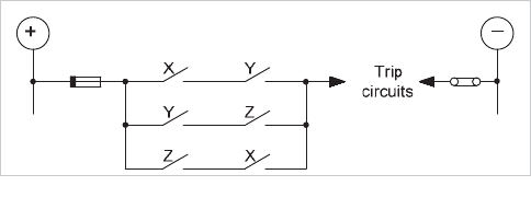
Security of both stability and operation is obtained by providing
three independent channels (say X, Y and Z) whose outputs
are arranged in a ‘two-out-of three’ voting arrangement, as
shown in Figure 15.1.
Figure 15.1: Two-out-of-three principle
15.4 TYPES OF PROTECTION SYSTEM
A number of busbar protection systems have been devised:
a.
system protection used to cover busbars
b.
frame-earth protection
c.
differential protection
d.
phase comparison protection
e.
directional blocking protection
Of these, (a) is suitable for small substations only. Type (d) is
often seen nowadays only as a supervision check element
within biased differential numerical schemes. Type (e) is
receiving greater acceptance nowadays when implemented as
IEC 61850 GOOSE-based schemes using overcurrent relays,
as described in section 15.11. Detailed discussion of types (b)
and (c) occupies most of this chapter.
Early forms of biased differential protection for busbars, such
as versions of 'Translay' protection and also a scheme using
harmonic restraint, were superseded by unbiased high
impedance differential protection.
The relative simplicity of the latter, and more importantly the
relative ease with which its performance can be calculated,
have ensured its success up to the present day.
But in the 1980’s the advances in semiconductor technology,
coupled with a
more pressing need to be able to accommodate
CTs of unequal ratio, led to the re-introduction of biased
schemes, generally using static relay designs, particularly for
the most extensive and onerous applications.
Frame-earth protection systems have been in use for many
years, mainly associated with smaller busbar protection
schemes at distribution voltages and for metalclad busbars
(e.g.
SF
6
insulated busbars). However, it has often been quite
common for a unit protection scheme to be used in addition, to
provide two separate means of fault detection.
The different types of protection are described in the following
sections.
15.5 SYSTEM PROTECTION SCHEMES
System protection that includes overcurrent or distance
systems will inherently give protection cover to the busbars.
© 2011 Alstom Grid. Single copies of this document may be filed or printed for personal non-commercial use and must include this
copyright notice but may not be copied or displayed for commercial purposes without the prior written permission of Alstom Grid.

Network Protection & Automation Guide
15-4
Overcurrent protection will only be applied to relatively simple
distribution systems, or as a back-up protection, set to give a
considerable time delay. Distance protection will provide cover
for busbar faults with its second and possibly subsequent
zones. In both cases the busbar protection obtained is slow
and suitable only for limiting the consequential damage.
The only exception is the case of a mesh-connected substation,
in which the current transformers are located at the circuit
breakers. Here, the busbars are included, in sections, in the
individual zones of the main circuit protection, whether this is
of unit type or not. In the special case when
the current
transformers are located on the line side of the mesh, the
circuit protection will not cover the busbars in the
instantaneous zone and separate busbar protection, known as
mesh-corner protection, is generally used see section 15.7.2
for details.
15.6 FRAME-EARTH PROTECTION (HOWARD
PROTECTION)
Frame leakage protection has been extensively used in the past
in many different situations. There are several variations of
frame leakage schemes available, providing busbar protection
schemes with different capabilities. The following sections
schemes have thus been retained for historical and general
reference purposes. A considerable number of schemes are
still in service and frame leakage may provide an acceptable
solution in particular circumstances. However, the need to
insulate the switchboard frame and provide cable gland
insulation and the availability of alternative schemes using
numerical relays, has contributed to a decline in use of frame
leakage systems.
15.6.1 Single-Busbar Frame-Earth Protection
This is purely an earth fault system and, in principle, involves
simply measuring the fault current flowing from the
switchgear frame to earth. A current transformer is mounted
on the earthing conductor and is used to energise a simple
instantaneous relay as shown in Figure 15.2.
Figure 15.2: Single zone frame-earth protection
No other earth connections of any type, including incidental
connections to structural steelwork are allowed. This
requirement is so that:
x the principal earth connection and current transformer
are not shunted, thereby raising the effective setting.
An increased effective setting gives rise to the possibility
of relay maloperation. This risk is small in practice
x earth current flowing to a fault elsewhere on the system
cannot flow into or out of the switchgear fra
me via two
earth connections, as this might lead to a spurious
operation
The switchgear must be insulated as a whole, usually by
standing it on concrete. Care must be taken that the
foundation bolts do not touch the steel reinforcement;
sufficient concrete must be cut away at each hole to permit
grouting-in with no risk of touching metalwork. The insulation
to earth finally achieved will not be high, a value of 10 ohms
being satisfactory.
When planning the earthing arrangements of a frame-leakage
scheme, the use of one common electrode for both the
switchgear frame and the power system neutral point is
preferred, because the fault path would otherwise include the
two earthing electrodes in series. If either or both of these are
of high resistance or have inadequate current carrying
capacity, the fault current may be limited to such an extent
that the protection equipment becomes inoperative. In
addition, if the electrode earthing the switchgear frame is the
offender, the potential of the frame may be raised to a
dangerous value. The use of a common earthing electrode of
© 2011 Alstom Grid. Single copies of this document may be filed or printed for personal non-commercial use and must include this
copyright notice but may not be copied or displayed for commercial purposes without the prior written permission of Alstom Grid.
Chapter 15 Busbar Protection
15-5
adequate rating and low resistance ensures sufficient current
for scheme operation and limits the rise in frame potential.
When the system is resistance earthed, the earthing
connection from the switchgear frame is made between the
bottom of the earthing resistor and the earthing electrode.
Figure 15.3 illustrates why a lower limit of 10 ohms insulation
resistance between frame and earth is necessary.
Frame-leakage
current
transformer
Earthing
electrode
resistance
Frame insulation
earth
resistance to
Earth
bar
I
F
=I
1
+I
2
Switchgear
frame
Switchgear frame
bonding bar
Generator
System
earthing
resistor
Outgoing
feeder
I
1
+I
2
I
1
I
1
I
2
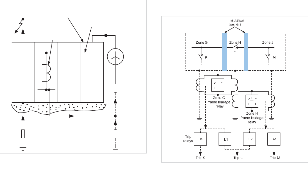
Figure 15.3: Current distribution for external fault
Under external fault conditions, the current I
F
flows through
the frame-leakage current transformer. If the insulation
resistance is too low, sufficient current may flow to operate the
frame-leakage relay, and, as the check feature is unrestricted,
this will also operate to complete the trip circuit. The earth
resistance between the earthing electrode and true earth is
seldom greater than 1:, so with 10: insulation resistance the
current
I
1
is limited to
10%
of the total earth fault current I
1
and I
2
. For this reason, the recommended minimum setting
for the scheme is about 30% of the minimum earth fault
current.
All cable glands must be insulated, to prevent the circulation of
spurious current through the frame and earthing system by
any voltages induced in the cable sheath. Preferably, the gland
insulation should be provided in two layers or stages, with an
interposing layer of metal, to facilitate the testing of the gland
insulation. A test level of 5kV from each side is suitable.
15.6.2 Frame-Earth Protection - Sectioned Busbars
Section 15.6.1 covered the basic requirements for a system to
protect switchgear as a whole. When the busbar is divided
into sections, these can be protected separately, provided the
frame is also sub-divided, the sections mutually insulated, and
each provided with a separate earth conductor, current
transformer and relay.
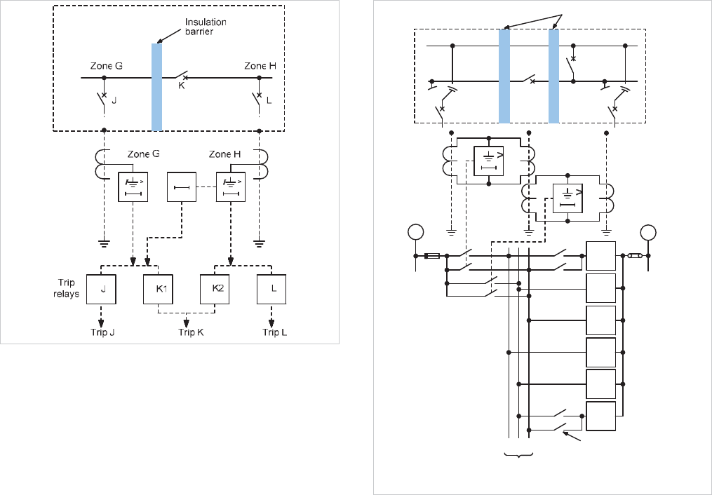
Ideally, the section switch should be treated as a separate
zone, as shown in Figure 15.4, and provided with either a
separate relay or two secondaries on the frame-leakage
current transformer, with an arrangement to trip both adjacent
zones. The individual zone relays trip their respective zone and
the section switch.
Figure 15.4: Three zone frame-earth scheme
If it is inconvenient to insulate the section switch frame on one
side, this switch may be included in that zone. It is then
necessary to intertrip the other zone after approximately 0.5
seconds if a fault persists after the zone including the section
switch has been tripped. This is illustrated in Figure 15.5.
© 2011 Alstom Grid. Single copies of this document may be filed or printed for personal non-commercial use and must include this
copyright notice but may not be copied or displayed for commercial purposes without the prior written permission of Alstom Grid.
Network Protection & Automation Guide
15-6
Figure 15.5: Frame-earth scheme: bus section breaker insulated on
one side only
For the above schemes to function it is necessary to have a
least one infeed or earthed source of supply, and in the latter
case it is essential that this source of supply be connected to
the side of the switchboard not containing the section switch.
Further, if possible, it is preferable that an earthed source of
supply be provided on both sides of the switchboard, in order
to ensure that any faults that may develop between the
insulating barrier and the section switch will continue to be fed
with fault current after the isolation of the first half of the
switchboard, and thus allow the fault to be removed. Of the
two arrangements, the first is the one normally recommended,
since it provides instantaneous clearance of busbar faults on all
sections of the switchboard.
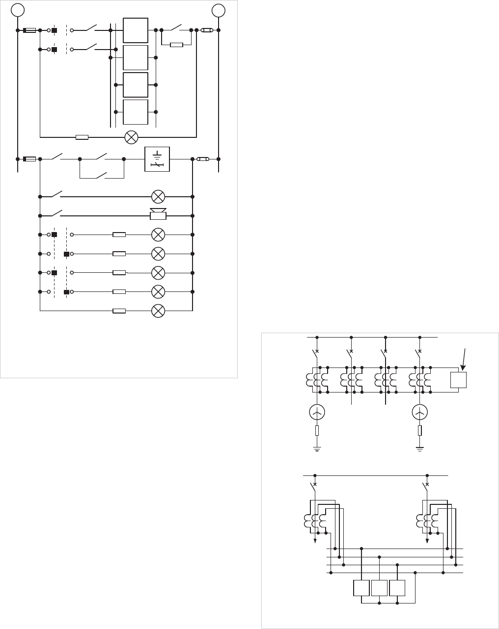
15.6.3 Frame-Earth Scheme - Double Bus Substation
It is not generally feasible to separately insulate the metal
enclosures of the main and auxiliary busbars. Protection is
therefore generally provided as for single bus installations, but
with the additional feature that circuits connected to the
auxiliary bus are tripped for all faults, as shown in Figure 15.6.
I
I
KN
L
Zone G
Zone H
Insulation barriers
K
_
M
1
M
2
L
1
L
2
N
GHJ
h
1
j
2
Busbar isolator
auxiliary switches
D.C. zone
bus wires
j
1
g
1
Zone J
g
1
j
1
h
1
j
2
M
+
Zone G
relay
Zone H
relay
Tripping
relays
Figure 15.6: Frame-earth scheme for double busbar substation
15.6.4 Frame-Earth Protection - Check System
On all but the smallest equipments, a check system should be
provided to guard against such contingencies as operation due
to mechanical shock or mistakes made by personnel. Faults in
the low voltage auxiliary wiring must also be prevented from
causing operation by passing current to earth through the
switchgear frame. A useful check is provided by a relay
energised by the system neutral current, or residual current. If
the neutral check cannot be provided, the frame-earth relays
should have a short time delay.
When a check system is used,
instantaneous relays can be
used, with a setting of 30% of the minimum earth fault current
and an operating time at five times setting of 15 milliseconds
or less.
Figure 15.7 shows a frame-leakage scheme for a metalclad
switchgear installation similar to that shown in Figure 15.4
and incorporating a neutral current check obtained from a
suitable zero sequence current source, such as that shown in
Figure 15.2.
© 2011 Alstom Grid. Single copies of this document may be filed or printed for personal non-commercial use and must include this
copyright notice but may not be copied or displayed for commercial purposes without the prior written permission of Alstom Grid.
Chapter 15 Busbar Protection
15-7
K
In Out
GH
L
1
L
2
M
L5
CSS-G
64A-1
64B-1
CSS-G
CSS-H
L3
L4
L3
L4
L6
74-1
74-2
64B-2
64A-2
I
>
A
l
a
r
m
c
a
n
c
e
l
l
a
t
i
o
n
r
e
l
a
y
Control selector switch protection in/protection out
Busbar protection in service lamp
Busbar protection out of service lamp
Tripping supply healthy lamp
Alarm and indication supply healthy lamp
L5
L6
74
CSS
L3
L4
CSS-H
64CH-2
In Out
64CH-1
Trip relays
+
-
Figure 15.7: Typical tripping and alarm circuits for a frame-leakage
scheme
The protection relays used for the discriminating and check
functions are of the attracted armature type, with two
normally open self reset contacts. The tripping circuits cannot
be complete unless both the discriminating and check relays
operate; this is because the discriminating and check relay
contacts are connected in series. The tripping relays are of the
attracted armature type.
It is usual to supervise the satisfactory operation of the
protection scheme with audible and visual alarms and
indications for the following:
x busbar faults
x busbar protection in service
x busbar protection out of service
x tripping supply healthy
x alarm supply healthy
To enable the protection equipment of each zone to be taken
out of service independently during maintenance periods,
isolating switc
hes - one switch per zone - are provided in the
trip supply circuits and an alarm cancellation relay is used.
15.7 DIFFERENTIAL PROTECTION PRINCIPLES
The Merz-Price principle is applicable to a multi-terminal zone
such as a busbar. The principle is a direct application of
Kirchhoff's first law. Usually, the circulating current
arrangement is used, in which the current transformers and
interconnections
form an analogue of the busbar and circuit
connections. A relay connected across the CT bus wires
represents a fault path in
the primary system in the analogue
and hence is not energised until a fault occurs on the busbar; it
then receives an input that, in principle at least, represents the
fault current.
The scheme may consist of a single relay connected to the bus
wires connecting all the current transformers in parallel, one
set per circuit, associated with a particular zone, as shown in
Figure 15.8(a). This will give earth fault protection for the
busbar. This arrangement has often been thought to be
adequate.
If the current transformers are connected as a balanced group
for each phase together with a three-element relay, as shown
in Figure 15.8(b), additional protection for phase faults can be
obtained.
a) Basic circulating current scheme (earth fault protection only)
I
d
>
GHJ K
D
i
f
f
e
r
e
n
t
i
a
l
r
e
l
a
y
Differential relay
C
N
B
A
G
I
d
>
H
b) Phase and earth fault circulating current scheme using
three-element relay
I
d
> I
d
>
Figure 15.8: Circulating current scheme
The phase and earth fault settings are identical, and this
© 2011 Alstom Grid. Single copies of this document may be filed or printed for personal non-commercial use and must include this
copyright notice but may not be copied or displayed for commercial purposes without the prior written permission of Alstom Grid.
Network Protection & Automation Guide
15-8
scheme is recommended for its ease of application and good
performance.
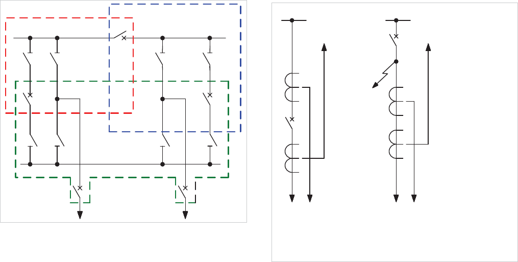
15.7.1 Differential Protection for Sectionalised and
Duplicate Busbars
Each section of a divided bus is provided with a separate
circulating current system. The zones so formed are over-
lapped across the section switches, so that a fault on the latter
will trip the two adjacent zones. This is illustrated in Figure
15.9.
Tripping two zones for a section switch fault can be avoided by
using the time-delayed technique of section 15.6.2. However
instantaneous operation is the preferred choice.
Zone BZone A
BC
Zone C
BS
BC
Figure 15.9: Zones of protection for double bus station
For double bus installation, the two busbars will be treated as
separate zones. The auxiliary busbar zone will overlap the
appropriate main busbar zone at the bus coupler.
Since any circuit may be transferred from one busbar to the
other by isolator switches, these and the associated tripping
circuit must also be switched to the appropriate zone by 'early
make' and 'late break' auxiliary contacts. This is to ensure that
when the isolators are closing, the auxiliary switches make
before the main contacts of the isolator, and that when the
isolators are opened, their main contacts part before the
auxiliary switches open. The result is that the secondary
circuits of the two zones concerned are briefly paralleled while
the circuit is being transferred; these two zones have in any
case been united through the circuit isolators during the
transfer operation.
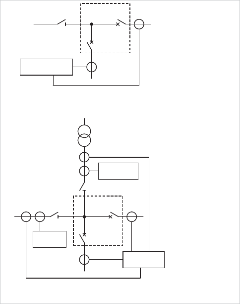
15.7.2 Location of Current Transformers
Ideally, the separate discriminating zones should overlap each
other and also the individual circuit protections. The overlap
should occur across a circuit breaker, so that the latter lies in
both zones. For this arrangement it is necessary to install
current transformers on both sides of the circuit breakers,
which is economically possible with many but not all types of
switchgear. With both the circuit and the bus protection
current transformers on the same side of the circuit breakers,
the zones may be overlapped at the current transformers, but a
fault between the CT location and the circuit breaker will not
be completely isolated. This matter is important in all
switchgear to which these conditions apply, and is particularly
important in the case of outdoor switchgear where separately
mounted, multi-secondary current transformers are generally
used. The conditions are shown in Figure 15.10.
protection
Circuit
-fault shown not cleared by circuit protection
b. Current transformers mounted on circuit side only of breaker
-no unprotected region
a. Current transformers mounted on both sides of breaker
Fault
Bus protection
(a) (b)
Figure 15.10: Unprotected zone with current transformers mounted
on one side of the circuit breaker only
Figure 15.10(a) shows the ideal arrangement in which both
the circuit and busbar zones are overlapped leaving no region
of the primary circuit unprotected.
Figure 15.10(b) shows how mounting all current transformers
on the circuit side of the breaker results in a small region of the
primary circuit unprotected. This unprotected region is
typically referred to as the ‘short zone’. The fault shown will
cause operation of the busbar protection, tripping the circuit
breaker, but the fault will continue to be fed from the circuit, if
a source of power is present. It is necessary for the bus
protection to intertrip the far end of the circuit protection, if the
latter is of the unit type.
With reference to Figure 15.10(b), special ‘short zone’
protection can be provided to detect that the circuit breaker
© 2011 Alstom Grid. Single copies of this document may be filed or printed for personal non-commercial use and must include this
copyright notice but may not be copied or displayed for commercial purposes without the prior written permission of Alstom Grid.
Chapter 15 Busbar Protection
15-9
has opened but that the fault current is still flowing. Under
these conditions, the protection can initiate an intertrip to the
remote end of the circuit. This technique may be used,
particularly when the circuit includes a generator. In this case
the intertrip proves that the fault is in the switchgear
connections and not in the generator; the latter is therefore
tripped electrically but not shut down on the mechanical side
so as to be immediately ready for further service if the fault can
be cleared.
15.7.2.1 CT locations for mesh-connected substations
The protection of busbars in mesh connected substations gives
rise to additional considerations in respect of CT location. A
single mesh corner is shown in Figure 15.11(a). Where only
one connection to the mesh is made at a corner, CTs located
as shown will provide protection not only to the line but the
corner of the mesh included between them. However, this
arrangement cannot be used where more than one connection
is made to a mesh corner. This is because a fault on any of the
connected circuits would result in disconnection of them all,
without any means of determining the faulted connection.
Protection CTs must therefore be located on each connection,
as shown in Figure 15.11(b). This leaves the corner of the
mesh unprotected, so additional CTs and a relay to provide
mesh-corner protection are added, as also shown in Figure
15.11(b).
Mesh corner
protection
(Note 2)
Mesh corner
protection
Line
protection
Transformer
(b) CT arrangements for protection - additional mesh corner protection required
Note 2: Multiple circuits may be connected to the mesh corner
Note 1: Only 1 connection to the mesh corner permitted
(a) CT arrangements for protection including mesh corner
Line protection
relay
(Note 1)
Mesh corner
Figure 15.11: Mesh-corner protection
15.8 HIGH IMPEDANCE DIFFERENTIAL
PROTECTION
This form of protection is still in common use. The
considerations that have to be taken into account are detailed
in the following sections.
15.8.1 Stability
The incidence of fault current with an initial unilateral transient
component causes an abnormal build-up of flux in a current
transformer, as described in section 15.8.2. When through-
fault current
traverses a zone protected by a differential
system, the transient flux produced in the current transformers
is not detrimental as long as it remains within the substantially
linear range of the magnetising characteristic. With fault
current of appreciable magnitude and long transient time
constant, the flux density will pass into the saturated region of
the characteristic; this will not in itself produce a spill output
from a pair of balancing current transformers provided that
these are identical and equally burdened. A group of current
transformers, though they may be of the same design, will not
be completely identical, but a more important factor is
inequality of burden. In the case of a differential system for a
busbar, an external fault may be fed through a single circuit,
the current being supplied to the busbar through all other
circuits. The faulted circuit is many times more heavily loaded
than the others and the corresponding current transformers
are likely to be heavily saturated, while those of the other
circuits are not. Severe unbalance is therefore probable,
which, with a relay of normal burden, could exceed any
acceptable current setting. For this reason such systems were
at one time always provided with a time delay. This practice
is, however, no longer acceptable.
It is not feasible to calculate the spill current that may occur,
but, fortunately, this is not necessary; an alternative approach
provides both the necessary information and the technique
required to obtain a high performance.
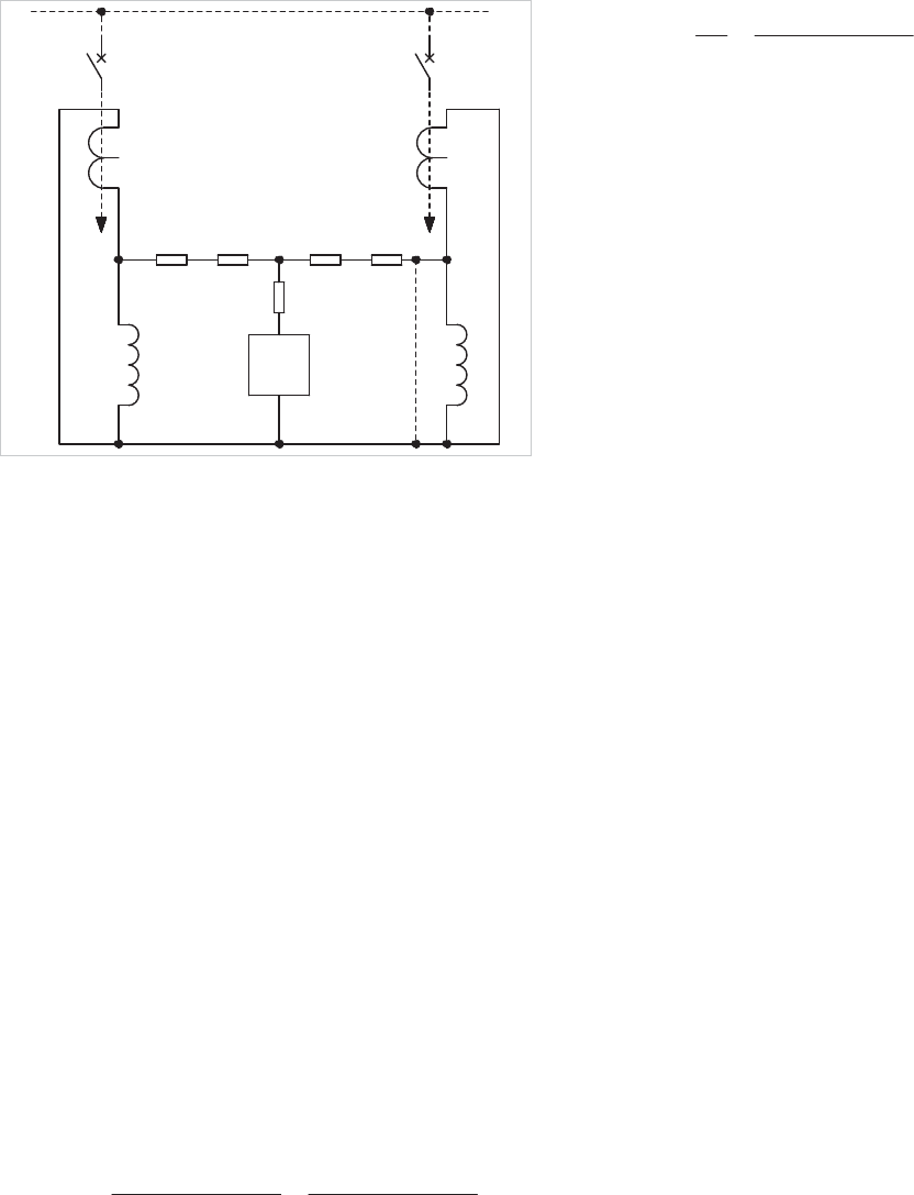
An equivalent circuit, as in Figure 15.12, can represent a
circulating current system.
© 2011 Alstom Grid. Single copies of this document may be filed or printed for personal non-commercial use and must include this
copyright notice but may not be copied or displayed for commercial purposes without the prior written permission of Alstom Grid.
Network Protection & Automation Guide
15-10
I
d
>
G
H
R
CTG
R
LG
R
LH
R
CTH
Z
EG
Z
EH
R
R
Figure 15.12: Equivalent circuit of circulating current system
The current transformers are replaced in the diagram by ideal
current transformers feeding an equivalent circuit that
represents the magnetising losses and secondary winding
resistance, and also the resistance of the connecting leads.
These circuits can then be interconnected as shown, with a
relay connected to the junction points to form the complete
equivalent circuit.
Saturation has the effect of lowering the exciting impedance,
and is assumed to take place severely in current transformer
H
until, at the limit, the shunt impedance becomes zero and the
CT can produce no output. This condition is represented by a
short circuit, shown in broken line, across the exciting
impedance. It should be noted that this is not the equivalent
of a physical short circuit, since it is behind the winding
resistance
R
CTH
.
Applying the Thévenin method of solution, the voltage
developed across the relay will be given by:
CTHLHff
RRIV
Equation 15.1
The current through the relay is given by:
CTHLHR
CTHLHf
CTHLHR
f
R
RRR
RRI
RRR
V
I
)(
Equation 15.2
If R
R
is small, I
R
will approximate to I
f
, which is unacceptable.
On the other hand, if
R
R
is large I
R
is reduced. Equation 15.2
can be written, with little error, as follows
:
R
CTHLHf
R
f
R
R
RRI
R
V
I
)(
Equation 15.3
or alternatively:
CTHLHffRR
RRIVRI
Equation 15.4
It is clear that, by increasing R
R
, the spill current I
R
can be
reduced below any specified relay setting.
R
R
is frequently
increased by the addition of a series-connected resistor which
is known as the stabilising resistor.
It can also be seen from Equation 15.4 that it is only the
voltage drop in the relay circuit at setting current that is
important. The relay can be designed as a voltage measuring
device consuming negligible current; and provided its setting
voltage exceeds the value
V
f
of Equation 15.4, the system will
be stable. In fact, the setting voltage need not exceed
V
f
, since
the derivation of Equation 15.4 involves an extreme condition
of unbalance between the G and H current transformers that is
not completely realised. So a safety margin is built-in if the
voltage setting is made equal to
V
f
.
It is necessary to realise that the value of
I
f
to be inserted in
Equation 15.4 is the complete function of the fault current and
the spill current
I
R
through the relay, in the limiting condition,
will be of the same form. If the relay requires more time to
operate than the effective duration of the d.c. transient
component, or has been designed with special features to
block the d.c. component, then this factor can be ignored and
only the symmetrical value of the fault current need be entered
in Equation 15.4
.
If the relay setting voltage,
S
V , is made
equal to
V
f
, that is, I
f
(R
L
+ R
CT
), an inherent safety factor of
the order of two will exist.
In the case of a faster relay, capable of operating in one cycle
and with no special features to block the d.c. component, it is
the r.m.s. value of the first offset wave that is significant. This
value, for a fully offset waveform with no d.c. decrement, is
3I
f
. If settings are then chosen in terms of the symmetrical
component of the fault current, the
3 factor which has been
ignored will take up most of the basic safety factor, leaving
only a very small margin.
Finally, if a truly instantaneous relay were used, the relevant
value of
I
f
would be the maximum offset peak. In this case,
the factor has become less than unity, possibly as low as 0.7.
It is therefore possible to rewrite Equation 15.4 as:
© 2011 Alstom Grid. Single copies of this document may be filed or printed for personal non-commercial use and must include this
copyright notice but may not be copied or displayed for commercial purposes without the prior written permission of Alstom Grid.

Chapter 15 Busbar Protection
15-11
CTL
S
SL
RR
VK
I
u
Equation 15.5
where:
I
SL
= stability limit of scheme
V
S
= relay circuit voltage setting
R
L
+ R
CT
= lead + CT winding resistance
K = factor depending on relay design (range 0.7 - 2.0)
It remains to be shown that the setting chosen is suitable in
section 15.8.2.
The current transformers will have an excitation curve which
has not so far been related to the relay setting voltage, the
latter being equal to the maximum nominal voltage drop
across the lead loop and the CT secondary winding resistance,
with the maximum secondary fault current flowing through
them. Under in-zone fault conditions it is necessary for the
current transformers to produce sufficient output to operate
the relay. This will be achieved provided the CT knee-point
voltage exceeds the relay setting. In order to cater for errors, it
is usual to specify that the current transformers should have a
knee-point e.m.f. of at least twice the necessary setting
voltage; a higher multiple is of advantage in ensuring a high
speed of operation.
15.8.2 Effective Setting or Primary Operating Current
The minimum primary operating current is a further criterion
of the design of a differential system. The secondary effective
setting is the sum of the relay minimum operating current and
the excitation losses in all parallel connected current
transformers, whether carrying primary current or not. This
summation should strictly speaking be vectorial, but is usually
done arithmetically. It can be expressed as:
eSSR
nIII
Equation 15.6
where:
I
R
= effective setting
I
S
= relay circuit setting current
I
eS
= CT excitation current at relay voltage setting
n = number of parallel connected CTs
Having established the relay setting voltage from stability
considerations, as shown in section 15.8.1, and knowing the
excitation characteristic of the current transformers, the
effective setting can be computed. The secondary setting is
converted to the primary operating current by multiplying by
the turns ratio of the current transformers. The operating
current so determined should be considered in terms of the
conditions of the application.
For a phase and earth fault scheme the setting can be based
on the fault current to be expected for minimum plant and
maximum system outage conditions. However, it should be
remembered that:
x phase-phase faults give only 86% of the three-phase
fault current
x fault arc resistance and earth path resistance reduce
fault currents somewhat
x a reasonable margin should be allowed to ensure that
relays operate quickly and d
ecisively
It is desirable that the primary effective setting should not
exceed 30% of the prospective
minimum fault current.
In the case of a scheme exclusively for earth fault protection,
the minimum earth fault current should be considered, taking
into account any earthing impedance that might be present as
well. Furthermore, in the event of a double phase to earth
fault, regardless of the inter-phase currents, only 50% of the
system e.m.f. is available in the earth path, causing a further
reduction in the earth fault current. The primary operating
current must therefore be not greater than 30% of the
minimum single-phase earth fault current.
In order to achieve high-speed operation, it is desirable that
settings should be still lower, particularly in the case of the
solidly earthed power system. The transient
component of the
fault current in conjunction with unfavourable residual flux in
the CT can cause a high degree of saturation and loss of
output, possibly leading to a delay of several cycles additional
to the natural operating time of the element. This will not
happen to any large degree if the fault current is a larger
multiple of setting; for example, if the fault current is five times
the scheme primary operating current and the CT knee-point
e.m.f. is three times the relay setting voltage, the additional
delay is unlikely to exceed one cycle.
The primary operating current is sometimes designed to exceed
the maximum expected circuit load in order to reduce the
possibility of false operation under load current as a result of a
broken CT lead. Desirable as this safeguard may be, it will be
seen that it is better not to increase the effective current
setting too much, as this will sacrifice some speed; the check
feature in any case, maintains stability.
An overall earth fault scheme for a large distribution board
may be difficult to design because of the large number of
current transformers paralleled together, which may lead to an
© 2011 Alstom Grid. Single copies of this document may be filed or printed for personal non-commercial use and must include this
copyright notice but may not be copied or displayed for commercial purposes without the prior written permission of Alstom Grid.
Network Protection & Automation Guide
15-12
excessive setting. It may be advantageous in such a case to
provide a three-element phase and earth fault scheme, mainly
to reduce the number of current transformers paralleled into
one group.
Extra-high-voltage substations usually present no such
problem. Using the voltage-calibrated relay, the current
consumption can be very small. A simplification can be
achieved by providing one relay per circuit, all connected to the
CT paralleling buswires. This enables the trip circuits to be
confined to the least area and reduces the risk of accidental
operation.
15.8.3 Check Feature
Schemes for earth faults only can be checked by a frame-earth
system, applied to the switchboard as a whole, no subdivision
being necessary.
For phase fault schemes, the check will usually be a similar
type of scheme applied to the switchboard as a single overall
zone. A set of current transformers separate from those used
in the discriminating zones should be provided. No CT
switching is required and no current transformers are needed
for the check zone in bus-coupler and bus-section breakers.
15.8.4 Supervision of CT Secondary Circuits
Any interruption of a CT secondary circuit up to the paralleling
interconnections will cause an unbalance in the system,
equivalent to the load being carried by the relevant primary
circuit. Even though this degree of spurious output is below
the effective setting the condition cannot be ignored, since it is
likely to lead to instability under any through fault condition.
Supervision can be carried out to detect such conditions by
connecting a sensitive alarm relay across the bus wires of each
zone. For a phase and earth fault scheme, an internal three-
phase rectifier can be used to effect a summation of the bus
wire voltages on to a single alarm element; see Figure 15.14
and Figure 15.13.
The alarm relay is set so that operation does not occur with the
protection system healthy under normal load. Subject to this
proviso, the alarm relay is made as sensitive as possible; the
desired effective setting is 125 primary amperes or 10% of the
lowest circuit rating, whichever is the greater.
Since a relay of this order of sensitivity is likely to operate
during through faults, a time delay, typically of three seconds,
is applied to avoid unnecessary alarm signals.
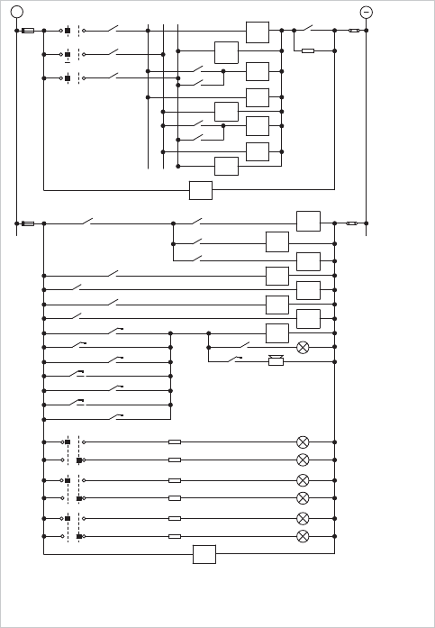
96
In Out
M1
CSS-M1
87M1-1
87M2-1
CSS-M1
L1
CSS-M2
In Out
87CH-1
+
D1
87R-1
CSS-R
M2 R
D2
96
E
96
a1
c1
96
F2
c2
b1
G
F1
96
96
H1
96
96
H2
D.C. Buswires
80
T
M2
R
30
30
M1
30
87R-2
87M2-2
87M1-2
87CH-2
M1X
95
95M1-1
M2X
95
95M2-1
95
RX
95R-1
95
CHX
95CH-1
30M1-1
74-1
74-2
30M2-1
30R-1
95M1X-1
95M2X-1
95RX-1
95CHX-1
L2
L1
L2
CSS-R
L2
L1
CSS-M2
80
74
Zone indicating relay 30
I
Zone bus wires shorting relay 95X
Alarm cancellation relay 74 Control selector switch CSS
D.C. volts supervision relay 80 Indicating lamp protection in serviceL1
High impedance circulating current relay 87 Indicating lamp protection out of serviceL2
Bus wires supervision relay
95
Figure 15.13: D.C. circuits for high impedance circulating current
scheme
© 2011 Alstom Grid. Single copies of this document may be filed or printed for personal non-commercial use and must include this
copyright notice but may not be copied or displayed for commercial purposes without the prior written permission of Alstom Grid.
