ALSTOM T&D. Network Protection And Automation Guide (NPAG)
Подождите немного. Документ загружается.

Chapter 17 Generator and Generator Transformer Protection
17-7
performance of the excitation system and its field-forcing
capability. Without the provision of fault current compounding
from generator CTs, an excitation system that is powered from
an excitation transformer at the generator terminals will
exhibit a pronounced fault current decrement for a terminal
fault. With failure to consider this effect, the potential exists
for the initial high fault current to decay to a value below the
overcurrent protection pick-up setting before a relay element
can operate, unless a low current setting and/or time setting is
applied. The protection would then fail to trip the generator.
The settings chosen must be the best compromise between
assured operation in the foregoing circumstances and
discrimination with the system protection and passage of
normal load current, but this can be impossible with plain
overcurrent protection.
In the more usual case of a generator that operates in parallel
with others and which forms part of an extensive
interconnected system, back-up phase fault protection for a
generator and its transformer will be provided by HV
overcurrent protection. This will respond to the higher-level
backfeed from the power system to a unit fault. Other
generators in parallel would supply this current and, being
stabilised by the system impedance, it will not suffer a major
decrement. This protection is usually a requirement of the
power system operator. Settings must be chosen to prevent
operation for external faults fed by the generator. It is
common for the HV overcurrent protection relay to provide
both time-delayed and instantaneous high-set elements. The
time-delayed elements should be set to ensure that the
protected items of plant cannot pass levels of through fault
current in excess of their short-time withstand limits. The
instantaneous elements should be set above the maximum
possible fault current that the generator can supply, but less
than the system-supplied fault current in the event of a
generator winding fault. This back-up protection will minimise
plant damage in the event of main protection failure for a
generating plant fault and instantaneous tripping for an HV-
side fault will aid the recovery of the power system and parallel
generation.
17.7.2 Voltage-Dependent Overcurrent Protection
The plain overcurrent protection setting difficulty referred to in
the previous section arises because allowance has to be made
both for the decrement of the generator fault current with time
and for the passage of full load current. To overcome the
difficulty of discrimination, the generator terminal voltage can
be measured and used to dynamically modify the basic relay
current/time overcurrent characteristic for faults close to the
generating plant. There are two basic alternatives for the
application of voltage-dependent overcurrent protection, which
are discussed in the following sections. The choice depends
upon the power system characteristics and level of protection
to be provided. Voltage-dependent overcurrent relays are often
found applied to generators used on industrial systems, as an
alternative to full differential protection.
17.7.2.1 Voltage Controlled Overcurrent Protection
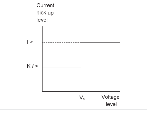
Voltage controlled overcurrent protection has two time/current
characteristics which are selected according to the status of a
generator terminal voltage measuring element. The voltage
threshold setting for the switching element is chosen according
to the following criteria.
x during overloads, when the system voltage is sustained
near normal, the overcurrent protection should have a
current setting above full load current and an operating
time characteristic that will prevent the
generating
plant from passing current to a remote external fault for
a period in excess of the plant short-time withstand
limits
x under close-up fault conditions, the busbar voltage
must fall below the voltage threshold so that the second
protection characteristic will be selected. This
characteristic should be set to allow relay operation
with fault current decrement
for a close-up fault at the
generator terminals or at the HV busbars. The
protection should also time-grade with external circuit
protection. There may be additional infeeds to an
external circuit fault that will assist with grading
Typical characteristics are shown in Figure 17.9.
Figure 17.9: Voltage controlled relay characteristics
17.7.2.2 Voltage Restrained Overcurrent Protection
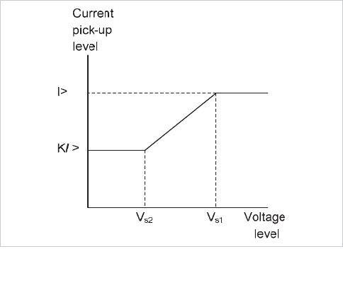
The alternative technique is to continuously vary the relay
element pickup setting with generator voltage variation
between upper and lower limits. The voltage is said to restrain
© 2011 Alstom Grid. Single copies of this document may be filed or printed for personal non-commercial use and must include this
copyright notice but may not be copied or displayed for commercial purposes without the prior written permission of Alstom Grid.
Network Protection & Automation Guide
17-8
the operation of the current element.
The effect is to provide a dynamic I.D.M.T. protection
characteristic, according to the voltage at the machine
terminals. Alternatively, the relay element may be regarded as
an impedance type with a long dependent time delay. In
consequence, for a given fault condition, the relay continues to
operate more or less independently of current decrement in the
machine. A typical characteristic is shown in Figure 17.10.
Figure 17.10: Voltage restrained relay characteristics
17.8 STATOR EARTH FAULT PROTECTION
Earth fault protection must be applied where impedance
earthing is employed that limits the earth fault current to less
than the pick-up threshold of the overcurrent and/or
differential protection for a fault located down to the bottom
5% of the stator winding from the star-point. The type of
protection required will depend on the method of earthing and
connection of the generator to the power system.
17.8.1 Direct-Connected Generators
A single direct-connected generator operating on an isolated
system will normally be directly earthed. However, if several
direct-connected generators are operated in parallel, only one
generator is normally earthed at a time. For the unearthed
generators, a simple measurement of the neutral current is not
possible, and other methods of protection must be used. The
following sections describe the methods available.
17.8.1.1 Neutral Overcurrent Protection
With this form of protection, a current transformer in the
neutral-earth connection energises an overcurrent relay
element. This provides unrestricted earth-fault protection and
so it must be graded with feeder protection. The relay element
will therefore have a time-delayed operating characteristic.
Grading must be carried out in accordance with the principles
detailed in Chapter 9. The setting should not be more than
33% of the maximum earth fault current of the generator, and
a lower setting would be preferable, depending on grading
considerations.
17.8.1.2 Sensitive Earth Fault Protection
This method is used in the following situations:
a. direct-connected generators operating in parallel
b. generators with high-impedance neutral earthing,
the earth fault current being limited to a few tens of
amps
c. installations where the resistance of the ground
fault path is very high, due to the nature of the
ground
In these cases, conventional earth fault protection as described
in Section 17.8.1.1 is of little use.
The principles of sensitive earth fault protection are described
in Sections 9.17.1, 9.18 and 9.19. The earth fault (residual)
current can be obtained from residual connection of line CTs, a
line-connected CBCT, or a CT in the generator neutral. The
latter is not possible if directional protection is used. The
polarising voltage is usually the neutral voltage displacement
input to the relay, or the residual of the three phase voltages,
so a suitable VT must be used. For Petersen Coil earthing, a
wattmetric technique (Section 9.19) can also be used.
For direct connected generators operating in parallel,
directional sensitive earth fault protection may be necessary.
This is to ensure that a faulted generator will be tripped before
there is any possibility of the neutral overcurrent protection
tripping a parallel healthy generator. When being driven by
residually-connected phase CTs, the protection must be
stabilised against incorrect tripping with transient spill current
in the event of asymmetric CT saturation when phase fault or
magnetising inrush current is being passed. Stabilising
techniques include the addition of relay circuit impedance
and/or the application of a time delay. Where the required
setting of the protection is very low in comparison to the rated
current of the phase CTs, it would be necessary to employ a
single CBCT for the earth fault protection to ensure transient
stability.
Since any generator in the paralleled group may be earthed, all
generators will require to be fitted with both neutral
overcurrent protection and sensitive directional earth fault
protection. The setting of the sensitive directional earth fault
protection is chosen to co-ordinate with generator differential
protection and/or neutral voltage displacement protection to
ensure that 95% of the stator winding is protected. Figure
17.11 illustrates the complete scheme, including optional
blocking signals where difficulties in co-ordinating the
© 2011 Alstom Grid. Single copies of this document may be filed or printed for personal non-commercial use and must include this
copyright notice but may not be copied or displayed for commercial purposes without the prior written permission of Alstom Grid.
Chapter 17 Generator and Generator Transformer Protection
17-9
generator and downstream feeder earth-fault protection occur.
Minimum earth fault level = I
F
=
I
I
>
>
>
U
rsd
R
e
I
>
>>
I
Feeder
Block*
R
e
I
I
>
Block*
>
>
U
rsd
Open
* Optional interlocked
earth-fault protection
if grading problems exist
V
ph-n
R
e
~
~
Figure 17.11: Comprehensive earth-fault protection scheme for
direct-connected generators operating in parallel
For cases (b) and (c) above, it is not necessary to use a
directional facility. Care must be taken to use the correct RCA
setting – for instance if the earthing impedance is mainly
resistive, this should be 0
o
. On insulated or very high
impedance earthed systems, an RCA of –90
o
would be used,
as the earth fault current is predominately capacitive.
Directional sensitive earth-fault protection can also be used for
detecting winding earth faults. In this case, the relay element
is applied to the terminals of the generator and is set to
respond to faults only within the machine windings. Hence
earth faults on the external system do not result in relay
operation. However, current flowing from the system into a
winding earth-fault causes relay operation. It will not operate
on the earthed machine, so that other types of earth-fault
protection must also be applied. All generators must be so
fitted, since any can be operated as the earthed machine.
17.8.1.3 Neutral Voltage Displacement Protection
In a balanced network, the addition of the three phase-earth
voltages produces a nominally zero residual voltage, since
there would be little zero sequence voltage present. Any earth
fault will set up a zero sequence system voltage, which will
give rise to a non-zero residual voltage. This can be measured
by a suitable relay element. The voltage signal must be derived
from a VT that is suitable – i.e. it must be capable of
transforming zero-sequence voltage, so 3-limb types and those
without a primary earth connection are not suitable. This
unbalance voltage provides a means of detecting earth faults.
The relay element must be insensitive to third harmonic
voltages that may be present in the system voltage waveforms,
as these will sum residually.
As the protection is still unrestricted, the voltage setting of the
relay must be greater than the effective setting of any
downstream earth fault protection. It must also be time-
delayed to co-ordinate with such protection. Sometimes, a
second high-set element with short time delay is used to
provide fast-acting protection against major winding earth
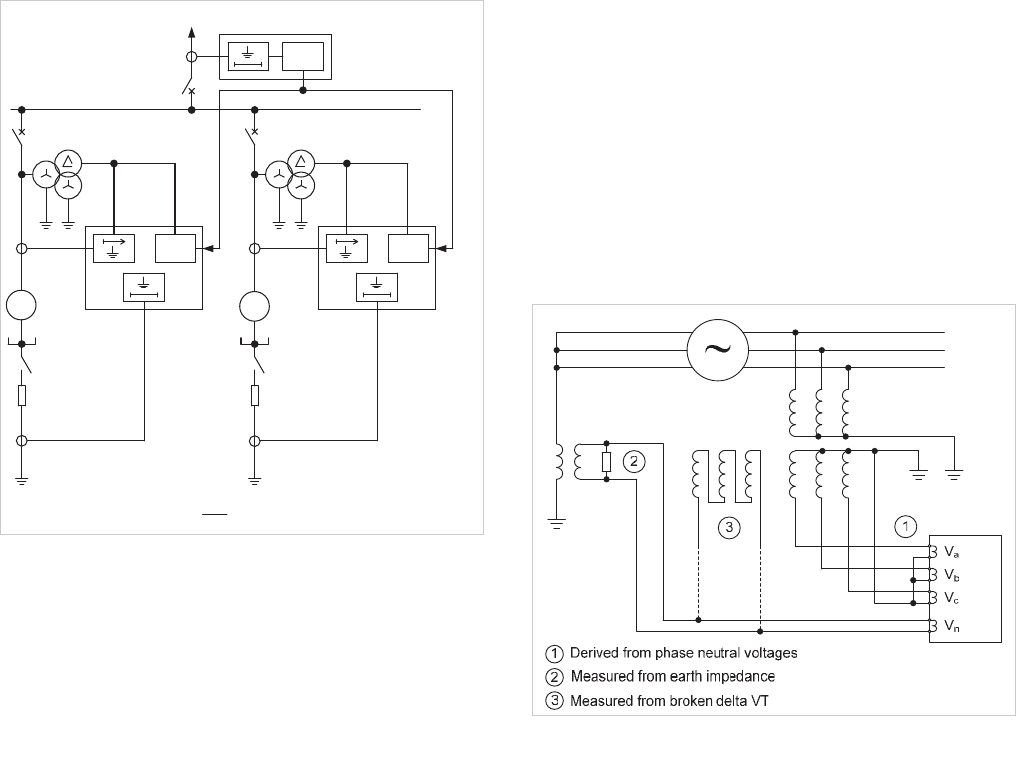
faults. Figure 17.12 illustrates the possible connections that
may be used.
Figure 17.12: Neutral voltage displacement protection
17.8.2 Indirectly-Connected Generators
As noted in Section 17.2, a directly-earthed generator-
transformer unit cannot interchange zero-sequence current
with the remainder of the network, and hence an earth fault
protection grading problem does not exist. The following
sections detail the protection methods for the various forms of
impedance earthing of generators.
17.8.2.1 High Resistance Earthing – Neutral Overcurrent
Protection
A current transformer mounted on the neutral-earth conductor
can drive an instantaneous and/or time delayed overcurrent
relay element, as shown in Figure 17.13. It is impossible to
provide protection for the whole of the winding, and Figure
17.13 also details how the percentage of winding covered can
be calculated. For a relay element with an instantaneous
setting, protection is typically limited to 90% of the winding.
This is to ensure that the protection will not maloperate with
zero sequence current during operation of a primary fuse for a
VT earth fault or with any transient surge currents that could
© 2011 Alstom Grid. Single copies of this document may be filed or printed for personal non-commercial use and must include this
copyright notice but may not be copied or displayed for commercial purposes without the prior written permission of Alstom Grid.
Network Protection & Automation Guide
17-10
flow through the interwinding capacitance of the step-up
transformer for an HV system earth fault.
A time-delayed relay is more secure in this respect, and it may
have a setting to cover 95% of the stator winding. Since the
generating units under consideration are usually large,
instantaneous and time delayed relay elements are often
applied, with settings of 10% and 5% of maximum earth fault
current respectively; this is the optimum compromise in
performance. The portion of the winding left unprotected for
an earth fault is at the neutral end. Since the voltage to earth
at this end of the winding is low, the probability of an earth
fault occurring is also low. Hence additional protection is often
not applied.
%100min)a1(
V
IsR
mina
R
aV
If
u
Figure 17.13: Earth fault protection of high-resistance earthed
generator stator winding using a current element
17.8.2.2 Distribution Transformer Earthing Using a
Current Element
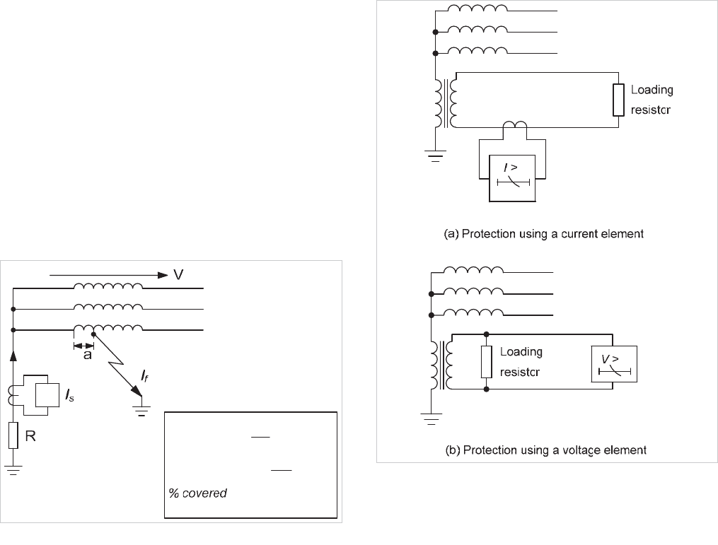
In this arrangement, shown in Figure 17.14(a), the generator
is earthed via the primary winding of a distribution
transformer. The secondary winding is fitted with a loading
resistor to limit the earth fault current. An overcurrent relay
element energised from a current transformer connected in the
resistor circuit is used to measure secondary earth fault
current. The relay should have an effective setting equivalent
to 5% of the maximum earth fault current at rated generator
voltage, in order to protect 95% of the stator winding. The
relay element response to third harmonic current should be
limited to prevent incorrect operation when a sensitive setting
is applied.
Figure 17.14: Generator winding earth-fault protection - distribution
transformer earthing
As discussed in Section 17.8.2.1, the protection should be time
delayed when a sensitive setting is applied, in order to prevent
maloperation under transient conditions. It also must grade
with generator VT primary protection (for a VT primary earth
fault). An operation time in the range 0.5s-3s is usual. Less
sensitive instantaneous protection can also be applied to
provide fast tripping for a heavier earth fault condition.
17.8.2.3 Distribution Transformer Earthing Using a
Voltage Element
Earth fault protection can also be provided using a voltage-
measuring element in the secondary circuit instead. The
setting considerations would be similar to those for the current
operated protection, but transposed to voltage. The circuit
diagram is shown in Figure 17.14(b).
Application of both voltage and current operated elements to a
generator with distribution transformer earthing provides some
advantages. The current operated function will continue to
operate in the event of a short-circuited loading resistor and
the voltage protection still functions in the event of an open-
circuited resistor. However, neither scheme will operate in the
event of a flashover on the primary terminals of the
transformer or of the neutral cable between the generator and
© 2011 Alstom Grid. Single copies of this document may be filed or printed for personal non-commercial use and must include this
copyright notice but may not be copied or displayed for commercial purposes without the prior written permission of Alstom Grid.
Chapter 17 Generator and Generator Transformer Protection
17-11
the transformer during an earth fault. A CT could be added in
the neutral connection close to the generator, to energise a
high-set overcurrent element to detect such a fault, but the
fault current would probably be high enough to operate the
phase differential protection.
17.8.2.4 Neutral Voltage Displacement Protection
This can be applied in the same manner as for direct-
connected generators (Section 17.8.1.3). The only difference
is that the are no grading problems as the protection is
inherently restricted. A sensitive setting can therefore be used,
enabling cover of up to 95% of the stator winding to be
achieved.
17.8.3 Restricted Earth Fault Protection
This technique can be used on small generators not fitted with
differential protection to provide fast acting earth fault
protection within a defined zone that encompasses the
generator. It is cheaper than full differential protection but
only provides protection against earth faults. The principle is
that used for transformer REF protection, as detailed in
Section 16.7. However, in contrast to transformer REF
protection, both biased low-impedance and high-impedance
techniques can be used.
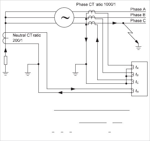
17.8.3.1 Low-Impedance Biased REF Protection
This is shown in Figure 17.15. The main advantage is that the
neutral CT can also be used in a modern relay to provide
conventional earth-fault protection and no external resistors
are used. Relay bias is required, as described in Section
10.4.2, but the formula for calculating the bias is slightly
different and also shown in Figure 17.15.
u
AN
DI FF N
highest of I I × scaling fact or
2
neut ral CT ratio 200
where scaling f act or = = = 0.2
phase CT ratio 1000
I scaling f act or I
BC
BIAS
ABC
,I ,I
I
III
Figure 17.15: Low impedance biased REF protection of a generator
The initial bias slope is commonly set to 0% to provide
maximum sensitivity, and applied up to the rated current of the
generator. It may be increased to counter the effects of CT
mismatch. The bias slope above generator rated current is
typically set to 150% of rated value. The initial current setting
is typically 5% of the minimum earth fault current for a fault at
the machine terminals.
17.8.3.2 High Impedance REF Protection
The principle of high impedance differential protection is given
in Chapter 10 and also described further in Section 17.5.2.
The same technique can be used for earth-fault protection of a
generator, using three residually connected phase CTs
balanced against a similar single CT in the neutral connection.
Settings of the order of 5% of maximum earth fault current at
the generator terminals are typical. The usual requirements in
respect of stabilising resistor and non-linear resistor to guard
against excessive voltage across the relay must be taken,
where necessary.
17.8.4 Earth Fault Protection for the Entire Stator
Winding
All of the methods for earth fault protection detailed so far
leave part of the winding unprotected. In most cases, this is of
no consequence as the probability of a fault occurring in the 5%
of the winding nearest the neutral connection is very low, due
to the reduced phase to earth voltage. However, a fault can
occur anywhere along the stator windings in the event of
insulation failure due to localised heating from a core fault. In
cases where protection for the entire winding is required,
perhaps for alarm only, there are various methods available.
17.8.4.1 Measurement of Third Harmonic Voltage
One method is to measure the internally generated third
harmonic voltage that appears across the earthing impedance
due to the flow of third harmonic currents through the shunt
capacitance of the stator windings etc. When a fault occurs in
the part of the stator winding nearest the neutral end, the third
harmonic voltage drops to near zero, and hence a relay
element that responds to third harmonic voltage can be used
to detect the condition. As the fault location moves
progressively away from the neutral end, the drop in third
harmonic voltage from healthy conditions becomes less, so
that at around 20-30% of the winding distance, it no longer
becomes possible to discriminate between a healthy and a
faulty winding. Hence, a conventional earth-fault scheme
should be used in conjunction with a third harmonic scheme,
to provide overlapping cover of the entire stator winding. The
measurement of third harmonic voltage can be taken either
from a star-point VT or the generator line VT. In the latter
© 2011 Alstom Grid. Single copies of this document may be filed or printed for personal non-commercial use and must include this
copyright notice but may not be copied or displayed for commercial purposes without the prior written permission of Alstom Grid.
Network Protection & Automation Guide
17-12
case, the VT must be capable of carrying residual flux, and this
prevents the use of 3-limb types. If the third harmonic voltage
is measured at the generator star point, an undervoltage
characteristic is used. An overvoltage characteristic is used if
the measurement is taken from the generator line VT. For
effective application of this form of protection, there should be
at least 1% third harmonic voltage across the generator neutral
earthing impedance under all operating conditions.
A problem encountered is that the level of third harmonic
voltage generated is related to the output of the generator.
The voltage is low when generator output is low. In order to
avoid maloperation when operating at low power output, the
relay element can be inhibited using an overcurrent or power
elements (kW, kVAr or kVA) and internal programmable logic.
17.8.4.2 Use of Low-Frequency Voltage Injection
Another method for protecting the entire stator winding of a
generator is to deploy signal injection equipment to inject a low
frequency voltage between the stator star point and earth. An
earth fault at any winding location will result in the flow of a
measurable injection current to cause protection operation.
This form of protection can provide earth fault protection when
the generator is at standstill, prior to run-up. It is also an
appropriate method to apply to variable speed synchronous
machines. Such machines may be employed for variable
speed motoring in pumped-storage generation schemes or for
starting a large gas turbine prime mover.
17.9 OVERVOLTAGE PROTECTION
Overvoltages on a generator may occur due to transient surges
on the network, or prolonged power frequency overvoltages
may arise from a variety of conditions. Surge arrestors may be
required to protect against transient overvoltages, but relay
protection may be used to protect against power frequency
overvoltages.
A sustained overvoltage condition should not occur for a
machine with a healthy voltage regulator, but it may be caused
by the following contingencies:
x defective operation of the automatic voltage regulator
when the machine is in
isolated operation
x operation under manual control with the voltage
regulator out of service. A sudden variation of the load,
in particular the reactive power component, will give
rise to a substantial change i
n voltage because of the
large voltage regulation inherent in a typical alternator
x sudden loss of load (due to tripping of outgoing feeders,
leaving the set isolated or feeding a very small load)
may cause a su
dden rise in terminal voltage due to the
trapped field flux and/or overspeed
Sudden loss of load should only cause a transient overvoltage
while the voltage regulator and governor act to correct the
situation. A maladjusted voltage regulator may trip to manual,
maintaining excitation at the value prior to load loss while the
generator supplies little or no load. The terminal voltage will
increase substantially, and in severe cases it would be limited
only by the saturation characteristic of the generator. A rise in
speed simply compounds the problem. If load that is sensitive
to overvoltages remains connected, the consequences in terms
of equipment damage and lost revenue can be severe.
Prolonged overvoltages may also occur on isolated networks,
or ones with weak interconnections, due to the fault conditions
listed earlier.
For these reasons, it is prudent to provide power frequency
overvoltage protection, in the form of a time-delayed element,
either IDMT or definite time. The time delay should be long
enough to prevent operation during normal regulator action,
and therefore should take account of the type of AVR fitted and
its transient response. Sometimes a high-set element is
provided as well, with a very short definite-time delay or
instantaneous setting to provide a rapid trip in extreme
circumstances. The usefulness of this is questionable for
generators fitted with an excitation system other than a static
type, because the excitation will decay in accordance with the
open-circuit time constant of the field winding. This decay can
last several seconds. The relay element is arranged to trip both
the main circuit breaker (if not already open) and the
excitation; tripping the main circuit breaker alone is not
sufficient.
17.10 UNDERVOLTAGE PROTECTION
Undervoltage protection was historically rarely fitted to
generators. It is sometimes used as an interlock element for
another protection function or scheme, such as field failure
protection or inadvertent energisation protection, where the
abnormality to be detected leads directly or indirectly to an
undervoltage condition. A transmission system undervoltage
condition may arise when there is insufficient reactive power
generation to maintain the system voltage profile and the
condition must be addressed to avoid the possible
phenomenon of system voltage collapse. However, it should
be addressed by the deployment of ’system protection’
schemes. The generation should not be tripped. The greatest
case for undervoltage protection being required would be for a
generator supplying an isolated power system or to meet the
public Utility demands for connection of embedded generation
(see Section 17.21).
In the case of generators feeding an isolated system,
undervoltage may occur for several reasons, typically
overloading or failure of the AVR. In some cases, the
© 2011 Alstom Grid. Single copies of this document may be filed or printed for personal non-commercial use and must include this
copyright notice but may not be copied or displayed for commercial purposes without the prior written permission of Alstom Grid.

Chapter 17 Generator and Generator Transformer Protection
17-13
performance of generator auxiliary plant fed via a unit
transformer from the generator terminals could be adversely
affected by prolonged undervoltage.
Where undervoltage protection is required, it should comprise
an undervoltage element and an associated time delay.
Settings must be chosen to avoid maloperation during the
inevitable voltage dips during power system fault clearance or
associated with motor starting. Transient reductions in voltage
down to 80% or less may be encountered during motor
starting.
17.11 LOW FORWARD POWER/REVERSE
POWER PROTECTION
Low forward power or reverse power protection may be
required for some generators to protect the prime mover.
Parts of the prime mover may not be designed to experience
reverse torque or they may become damaged through
continued rotation after the prime mover has suffered some
form of failure.
17.11.1 Low Forward Power Protection
Low forward power protection is often used as an interlocking
function to enable opening of the main circuit breaker for non-
urgent trips – e.g. for a stator earth fault on a high-impedance
earthed generator, or when a normal shutdown of a set is
taking place. This is to minimise the risk of plant overspeeding
when the electrical load is removed from a high-speed
cylindrical rotor generator. The rotor of this type of generator
is highly stressed mechanically and cannot tolerate much
overspeed. While the governor should control overspeed
conditions, it is not good practice to open the main circuit
breaker simultaneously with tripping of the prime mover for
non-urgent trips. For a steam turbine, for example, there is a
risk of overspeeding due to energy storage in the trapped
steam, after steam valve tripping, or in the event that the
steam valve(s) do not fully close for some reason. For urgent
trip conditions, such as stator differential protection operation,
the risk involved in simultaneous prime mover and generator
breaker tripping must be accepted.
17.11.2 Reverse Power Protection
Reverse power protection is applied to prevent damage to
mechanical plant items in the event of failure of the prime
mover. Table 17.1 gives details of the potential problems for
various prime mover types and the typical settings for reverse
power protection. For applications where a protection
sensitivity of better than 3% is required, a metering class CT
should be employed to avoid incorrect protection behaviour
due to CT phase angle errors when the generator supplies a
significant level of reactive power at close to zero power factor.
Table 17.1: Generator reverse power problems
The reverse power protection should be provided with a
definite time delay on operation to prevent spurious operation
with transient power swings that may arise following
synchronisation or in the event of a power transmission system
disturbance.
17.12 UNBALANCED LOADING
A three-phase balanced load produces a reaction field that, to
a first approximation, is constant and rotates synchronously
with the rotor field system. Any unbalanced condition can be
resolved into positive, negative and zero sequence
components. The positive sequence component is similar to
the normal balanced load. The zero sequence component
produces no main armature reaction.
17.12.1 Effect of Negative Sequence Current
The negative sequence component is similar to the positive
sequence system, except that the resulting reaction field
rotates in the opposite direction to the d.c. field system.
Hence, a flux is produced which cuts the rotor at twice the
rotational velocity, thereby inducing double frequency currents
in the field system and in the rotor body. The resulting eddy-
currents are very large and cause severe heating of the rotor.
So severe is this effect that a single-phase load equal to the
normal three-phase rated current can quickly heat the rotor
slot wedges to the softening point. They may then be extruded
under centrifugal force until they stand above the rotor surface,
when it is possible that they may strike the stator core.
A generator is assigned a continuous negative sequence rating.
Prime Mover
Motoring Power
(% of rated)
Possible Damage
Protection
Setting
Fire/explosion due to
unburnt fuel
Diesel Engine 5-25
Mechanical damage to
gearbox/shafts
10-15
(split shaft)
Gas Turbine
>50%
(single shaft)
Gearbox damage
0.2-2
(blades out of water)
Hydro
>2
(blades in water)
Blade and runner cavitation
Turbine blade damage
Steam Turbine 0.5-6
Gearbox damage on geared
sets
50% of motoring
power
© 2011 Alstom Grid. Single copies of this document may be filed or printed for personal non-commercial use and must include this
copyright notice but may not be copied or displayed for commercial purposes without the prior written permission of Alstom Grid.
Network Protection & Automation Guide
17-14
For turbo-generators this rating is low; standard values of 10%
and 15% of the generator continuous rating have been
adopted. The lower rating applies when the more intensive
cooling techniques are applied, for example hydrogen-cooling
with gas ducts in the rotor to facilitate direct cooling of the
winding.
Short time heating is of interest during system fault conditions
and it is usual in determining the generator negative sequence
withstand capability to assume that the heat dissipation during
such periods is negligible. Using this approximation it is
possible to express the heating by the law:
KtI
2
2
where:
I
2
= negative sequence component (per unit of MCR)
t = time (seconds)
K = constant proportional to the thermal capacity of the
generator rotor
For heating over a period of more than a few seconds, it is
necessary to allow for the heat dissipated. From a
combination of the continuous and short time ratings, the
overall heating characteristic can be deduced to be
:
K
tI
R
R
e
I
I
M
2
2
1
1
2
2
where:
I
2R
=
negative phase sequence continuous rating in per unit of
MCR
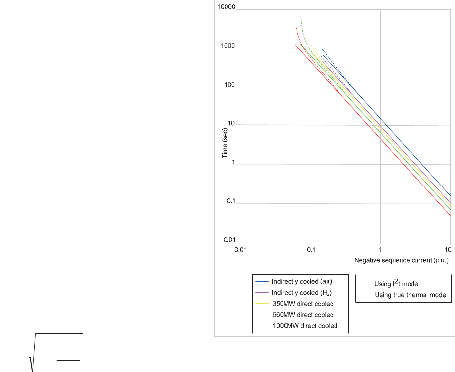
The heating characteristics of various designs of generator are
shown in Figure 17.16.
Figure 17.16: Typical negative phase sequence current withstand of
cylindrical rotor generators
17.12.2 Negative Phase Sequence Protection
This protection is applied to prevent overheating due to
negative sequence currents. Small salient-pole generators
have a proportionately larger negative sequence capacity and
may not require protection. Modern numerical relays derive
the negative sequence current level by calculation, with no
need for special circuits to extract the negative sequence
component. A true thermal replica approach is often followed,
to allow for:
x standing levels of negative sequence current below the
continuous withstand capability. This has the effect of
shortening the time to reach the critical temperature
after an increa
se in negative sequence current above
the continuous withstand capability
x cooling effects when negative sequence current levels
are below the continuous withstand capability
The advantage of this approach is that cooling effects are
modelled more accurately, but the disadvantage is that the
tripping characteristic may not follow the withstand
characteristic specified by the manufacturer accurately.
The typical relay element characteristic takes the form of
© 2011 Alstom Grid. Single copies of this document may be filed or printed for personal non-commercial use and must include this
copyright notice but may not be copied or displayed for commercial purposes without the prior written permission of Alstom Grid.

Chapter 17 Generator and Generator Transformer Protection
17-15
»
¼
º
«
¬
ª
¸
¸
¹
·
¨
¨
©
§
2
2
2
2
1log
I
I
I
K
t
set
e
set
Equation 17.1
where:
t = time to trip
2
¸
¸
¹
·
¨
¨
©
§
u
p
flc
g
I
I
KK
n
p
flc
cmrset
I
I
I
II u
¸
¸
¹
·
¨
¨
©
§
u
22
K
g
= negative sequence withstand coefficient (Figure 17.16)
I
2cmr
= generator maximum continuous
I
2
withstand
I
flc
= generator rated primary current
I
p
= CT primary current
I
n
= Relay rated current
Figure 17.16 also shows the thermal replica time characteristic
described by Equation 17.1, from which it will be seen that a
significant gain in capability is achieved at low levels of
negative sequence current. Such a protection element will also
respond to phase-earth and phase-phase faults where
sufficient negative sequence current arises. Grading with
downstream power system protection relays is therefore
required. A definite minimum time setting must be applied to
the negative sequence relay element to ensure correct grading.
A maximum trip time setting may also be used to ensure
correct tripping when the negative sequence current level is
only slightly in excess of the continuous withstand capability
and hence the trip time from the thermal model may depart
significantly from the rotor withstand limits.
17.13 PROTECTION AGAINST INADVERTENT
ENERGISATION
Accidental energisation of a generator when it is not running
may cause severe damage to it. With the generator at
standstill, closing the circuit breaker results in the generator
acting as an induction motor; the field winding (if closed) and
the rotor solid iron/damper circuits acting as rotor circuits.
Very high currents are induced in these rotor components, and
also occur in the stator, with resultant rapid overheating and
damage. Protection against this condition is therefore
desirable.
A combination of stator undervoltage and overcurrent can be
used to detect this condition. An instantaneous overcurrent
element is used, and gated with a three-phase undervoltage
element (fed from a VT on the generator side of the circuit
breaker) to provide the protection. The overcurrent element
can have a low setting, as operation is blocked when the
generator is operating normally. The voltage setting should be
low enough to ensure that operation cannot occur for transient
faults. A setting of about 50% of rated voltage is typical. VT
failure can cause maloperation of the protection, so the
element should be inhibited under these conditions.
17.14 UNDER/OVERFREQUENCY/
OVERFLUXING PROTECTION
These conditions are grouped together because these problems
often occur due to a departure from synchronous speed.
17.14.1 Overfluxing
Overfluxing occurs when the ratio of voltage to frequency is too
high. The iron saturates owing to the high flux density and
results in stray flux occurring in components not designed to
carry it. Overheating can then occur, resulting in damage.
The problem affects both direct-and indirectly-connected
generators. Either excessive voltage, or low frequency, or a
combination of both can result in overfluxing, a voltage to
frequency ratio in excess of 1.05p.u. normally being indicative
of this condition. Excessive flux can arise transiently, which is
not a problem for the generator. For example, a generator can
be subjected to a transiently high power frequency voltage, at
nominal frequency, immediately after full load rejection. Since
the condition would not be sustained, it only presents a
problem for the stability of the transformer differential
protection schemes applied at the power station (see Chapter
16 for transformer protection). Sustained overfluxing can arise
during run up, if excitation is applied too early with the AVR in
service, or if the generator is run down, with the excitation still
applied. Other overfluxing instances have occurred from loss
of the AVR voltage feedback signal, due to a reference VT
problem. Such sustained conditions must be detected by a
dedicated overfluxing protection function that will raise an
alarm and possibly force an immediate reduction in excitation.
Most AVRs have an overfluxing protection facility included.
This may only be operative when the generator is on open
circuit, and hence fail to detect overfluxing conditions due to
abnormally low system frequency. However, this facility is not
engineered to protection relay standards, and should not be
solely relied upon to provide overfluxing protection. A separate
relay element is therefore desirable and provided in most
modern relays.
It is usual to provide a definite time-delayed alarm setting and
an instantaneous or inverse time-delayed trip setting, to match
© 2011 Alstom Grid. Single copies of this document may be filed or printed for personal non-commercial use and must include this
copyright notice but may not be copied or displayed for commercial purposes without the prior written permission of Alstom Grid.
Network Protection & Automation Guide
17-16
the withstand characteristics of the protected generator and
transformer. It is very important that the VT reference for
overfluxing protection is not the same as that used for the
AVR.
17.14.2 Under/Overfrequency
The governor fitted to the prime mover normally provides
protection against overfrequency. Underfrequency may occur
as a result of overload of generators operating on an isolated
system, or a serious fault on the power system that results in a
deficit of generation compared to load. This may occur if a
grid system suffers a major fault on transmission lines linking
two parts of the system, and the system then splits into two. It
is likely that one part will have an excess of generation over
load, and the other will have a corresponding deficit.
Frequency will fall fairly rapidly in the latter part, and the
normal response is load shedding, either by load shedding
relays or operator action. However, prime movers may have to
be protected against excessively low frequency by tripping of
the generators concerned.
With some prime movers, operation in narrow frequency
bands that lie close to normal running speed (either above or
below) may only be permitted for short periods, together with
a cumulative lifetime duration of operation in such frequency
bands. This typically occurs due to the presence of rotor
torsional frequencies in such frequency bands. In such cases,
monitoring of the period of time spent in these frequency
bands is required. A special relay is fitted in such cases,
arranged to provide alarm and trip facilities if either an
individual or cumulative period exceeds a set time.
17.15 ROTOR FAULTS
The field circuit of a generator, comprising the field winding of
the generator and the armature of the exciter, together with
any associated field circuit breaker if it exists, is an isolated d.c.
circuit which is not normally earthed. If an earth fault occurs,
there will be no steady-state fault current and the need for
action will not be evident.
Danger arises if a second earth fault occurs at a separate point
in the field system, to cause the high field current to be
diverted, in part at least, from the intervening turns. Serious
damage to the conductors and possibly the rotor can occur
very rapidly under these conditions.
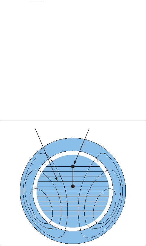
More damage may be caused mechanically. If a large portion
of the winding is short-circuited, the flux may adopt a pattern
such as that shown in Figure 17.17. The attracting force at
the surface of the rotor is given by:
S
8
2
AB
F
where:
A = area
B = flux density
It will be seen from Figure 17.17 that the flux is concentrated
on one pole but widely dispersed over the other and
intervening surfaces. The attracting force is in consequence
large on one pole but very weak on the opposite one, while flux
on the quadrature axis will produce a balancing force on this
axis. The result is an unbalanced force that in a large machine
may be of the order of 50-100 tons. A violent vibration is set
up that may damage bearing surfaces or even displace the
rotor by an amount sufficient to cause it to foul the stator
.
Short CircuitField Winding
Figure 17.17: Flux distribution on rotor with partial winding short
circuit
17.15.1 Rotor Earth-Fault Protection
Two methods are available to detect this type of fault. The first
method is suitable for generators that incorporate brushes in
the main generator field winding. The second method requires
at least a slip-ring connection to the field circuit:
x Potentiometer method
x A.C. injection method
17.15.1.1 Potentiometer Method
This is a scheme that was fitted to older generators, and it is
illustrated in Figure 17.18. An earth fault on the field winding
would produce a voltage across the relay, the maximum
voltage occurring for faults at the ends of the winding.
A ‘blind spot' would exist at the centre of the field winding. To
avoid a fault at this location remaining undetected, the tapping
© 2011 Alstom Grid. Single copies of this document may be filed or printed for personal non-commercial use and must include this
copyright notice but may not be copied or displayed for commercial purposes without the prior written permission of Alstom Grid.
