ALSTOM T&D. Network Protection And Automation Guide (NPAG)
Подождите немного. Документ загружается.

Chapter 16 Transformer and Transformer Feeder Protection
16-21
Unit
protection
Secondary ICT'sPrimary ICT's
R=1000A
R
stab
Yy0
relay
Yd1
600/1
Primary CT's
Yy0, 250/1 Yy0, 600/1
Secondary CT's
FLC = 175A
FLC = 525A
10MVA
33/11kV
Z=10%
Dyn11
I
d
>
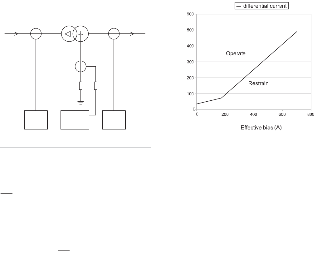
Figure 16.28: Transformer unit protection example
16.19.2.1 Ratio compensation
Transformer HV full load current on secondary of main CTs is:
7.0
250
175
Ratio compensation =
428.1
7.0
1
Select nearest value = 1.43
LV secondary current =
875.0
600
525
Ratio compensation =
14.1
875.0
1
16.19.2.2 Transformer unit protection settings
A current setting of 20% of the rated relay current is
recommended. This equates to 35A primary current. The
KBCH relay has a dual slope bias characteristic with fixed bias
slope settings of 20% up to rated current and 80% above that
level. The corresponding characteristic is shown in Figure
16.29.
Differential current (A)
Figure 16.29: Transformer unit protection characteristic
16.19.2.3 Restricted earth fault protection
The KBCH relay implements high-impedance Restricted Earth
Fault (REF) protection. Operation is required for a primary
earth fault current of 25% rated earth fault current (i.e. 250A).
The prime task in calculating settings is to calculate the value
of the stabilising resistor
R
stab
and stability factor
K
.
A stabilising resistor is required to ensure through fault stability
when one of the secondary CTs saturates while the others do
not. The requirements can be expressed as:
stabSS
RIV
And
lctfS
RRKIV 2!
where:
V
S
= stability voltage setting
V
K
= CT knee point voltage
K = relay stability factor
I
S
= relay current setting
R
CT
= CT winding resistance
R
1
= CT lead resistance
R
stab
= stabilising resistor.
For this example:
V
K
= 97V
R
CT
= 3.7
R
1
= 0.057
© 2011 Alstom Grid. Single copies of this document may be filed or printed for personal non-commercial use and must include this
copyright notice but may not be copied or displayed for commercial purposes without the prior written permission of Alstom Grid.
Network Protection & Automation Guide
16-22
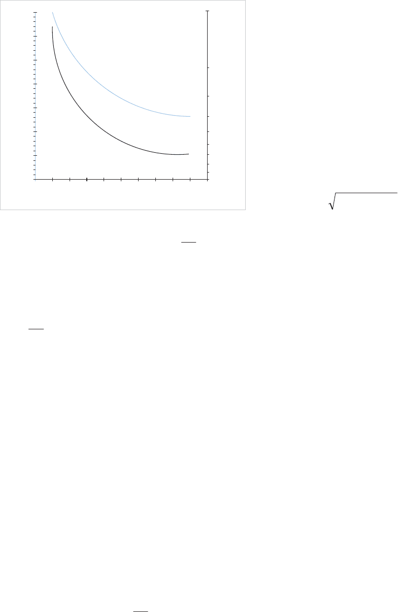
For the relay used, the various factors are related by the graph
of Figure 16.30.
10
20
30
40
50
70
60
123 4 5 6 7 8 9 10
0.9
0
1
0.8
0.7
0.6
0.5
0.4
0.3
0.2
0.1
V
k
/V
s
Overall operation time - milliseconds
K Factor
Overall Op
Time
K Factor
Unstable
Stable
Figure 16.30: REF operating characteristic for KBCH relay
Starting with the desired operating time, the
S
K
V
V
ratio and
K
factor can be found.
An operating of 40ms (2 cycles at 50Hz) is usually acceptable,
and hence, from Figure 16.30,
5.0,4 K
V
V
S
K
The maximum earth fault current is limited by the earthing
resistor to 1000A (primary). The maximum phase fault
current can be estimated by assuming the source impedance
to be zero, so it is limited only by transformer impedance to
5250A, or 10A secondary after taking account of the ratio
compensation. Hence the stability voltage can be calculated
as
V07.19057.027.3105.0V
S
uu
Hence,
Calculated
VV
K
28.7607.194 u
However,
Actual
V
K
= 91V and V
K
/V
S
= 4.77
Thus from Figure 16.30, with K = 0.5, the protection is
unstable.
By adopting an iterative procedure for values of V
K
/V
S
and K,
a final acceptable result of
6.0,55.4 K
V
V
S
K
is
obtained. This results in an operating time faster than 40ms.
The required earth fault setting current
I
op
is 250A. The
chosen E/F CT has an exciting current
I
e
of 1%, and hence
using the equation:
eSop
nIICTratioI u
where:
n = no of CTs in parallel (=4)
I
s
= 0.377, use
0.38
nearest settable value.
The stabilising resistance
R
stab
can be calculated as 60.21:.
The relay can only withstand a maximum of 3kV peak under
fault conditions. A check is required to see if this voltage is
exceeded – if it is, a non-linear resistor, known as a Metrosil,
must be connected across the relay and stabilising resistor.
The peak voltage is estimated using the formula:
KfKP
VVVV 22
where:
stablCTff
RRRIV 2
And
I
f
= fault current in secondary of CT circuit and substituting
values,
V
P
= 544V. Thus a Metrosil is not required.
16.19.3 Unit Protection for On-Load Tap Changing
Transformer
The previous example deals with a transformer having no taps.
In practice, most transformers have a range of taps to cater for
different loading conditions. While most transformers have an
off-load tap-changer, transformers used for voltage control in
a network are fitted with an on-load tap-changer. The
protection settings must then take the variation of tap-change
position into account to avoid the possibility of spurious trips at
extreme tap positions. For this example, the same transformer
as in Section 16.19.2 will be used, but with an on-load tapping
range of +5% to -15%. The tap-changer is located on the
primary winding, while the tap-step usually does not matter.
16.19.3.1 Ratio correction
In accordance with Section 16.8.4 the mid-tap position is used
to calculate the ratio correction factors. The mid tap position is
–5%, and at this tap position:
Primary voltage to give rated secondary voltage:
= 33 x 0.95 = 31.35kV and Rated Primary Current = 184A
Transformer HV full load current on secondary of main CTs is:
© 2011 Alstom Grid. Single copies of this document may be filed or printed for personal non-commercial use and must include this
copyright notice but may not be copied or displayed for commercial purposes without the prior written permission of Alstom Grid.

Chapter 16 Transformer and Transformer Feeder Protection
16-23
737.0
250
184
Ratio compensation =
36.1
737.0
1
LV secondary current =
875.0
600
525
Ratio compensation =
14.1
875.0
1
Both of the above values can be set in the relay.
16.19.3.2 Bias slope setting
The on-load tapping range of +5% to -15% gives rise to a
maximum excursion of r10% from the -5% mid-tap position.
As the differential scheme notionally balances at this mid-tap,
this means that as an approximation, the maximum
differential current that can flow when at top or bottom tap is
10% of the load (or fault current which may flow to an external
fault). Those relays having an adjustable k1 bias slope setting
should ensure that it is at least 10% higher than the percentage
excursion.
16.20 TRANSFORMER ASSET MANAGEMENT
Due to the high capital cost of transformers, and the need for
their in-service availability to be as high as possible to avoid
constraining load flows demanded on the network, protection
is no-longer the only concern. As cities expand, consumers’
lifestyle expectations raise, and electric vehicle recharging
loads become more prevalent, these combine to increase the
demand on the network - and it is through the transformers,
between the different voltage levels on the system, that the
demand is traditionally supplied. This increases the focus on
knowing the health of transformers, real-time, to be able to
schedule condition-based maintenance. Maintenance or
reconditioning at a time of the asset-owner’s choosing is far
more preferable than a forced unplanned outage due to failure.
This section provides an overview of techniques commonly
available in modern numerical transformer protection relays,
which can extend to asset management of the protected
transformer.
16.20.1 Loss of life monitoring
Ageing of transformer insulation is a time-dependent function
of temperature, moisture, and oxygen content. The moisture
and oxygen contributions to insulation deterioration are
minimised due to the preservation systems employed in the
design of most modern transformers. Therefore, temperature
is the key parameter in insulation ageing. Frequent excesses
of overloading will shorten the life-expectancy of the
transformer, due to the elevated winding temperatures.
Insulation deterioration is not uniform, and will be more
pronounced at hot-spots within the transformer tank.
Therefore, any asset management system intended to model
the rate of deterioration and current estimated state of the
insulation must do so based on simulated real-time hot spot
temperature algorithms. These models may take ambient
temperature, top-oil temperature, load current flowing, the
status of oil pumps (pumping or not), and the status of
radiator fans (forced cooling or not) as inputs.
The MiCOM P640 provides such a loss of life monitoring
facility, according to the thermal model defined in IEEE
Standard C57.91. The protection algorithm determines the
current rate of losing life, and uses that to indicate the
remaining years or hours until critical insulation health
statuses are likely to be reached. Such criticalities will relate
typically to known percentage degradations in the tensile
strength of the insulation, degradation in the degree of
polymerisation, and other life-loss factors. The asset owner
can be alerted in advance that an outage will be required for
reconditioning or rewinding, such that investment budgeting
can be made years and months ahead of time.
16.20.2 Through-fault monitoring
Loss of life monitoring serves to track the deterioration caused
by long term, repeated overloading. However, it is not the
right technique to monitor short-term heavy fault currents
which flow through the transformer, out to an external fault on
the downstream power system (e.g. fault
I
F2
in Figure 16.23).
Through faults are a major cause of transformer damage and
failure, as they stress the insulation and mechanical integrity -
such as the bracing of the windings.
A specific through-fault monitor is recommended to monitor
currents which are due to external faults passing through, and
so may range from 3.5 times up to tens of times the rated
current of the transformer. The MiCOM P640 performs an I
2
t
calculation when the through current exceeds a user-set
threshold, such that the heating effect of the square of the
maximum phase current, and the duration of the fault event
are calculated. Calculation results are added to cumulative
values, and monitored so that utilities can schedule
transformer maintenance or identify a need for system
reinforcement.
© 2011 Alstom Grid. Single copies of this document may be filed or printed for personal non-commercial use and must include this
copyright notice but may not be copied or displayed for commercial purposes without the prior written permission of Alstom Grid.
© 2011 Alstom Grid. Single copies of this document may be filed or printed for personal non-commercial use and must include this
copyright notice but may not be copied or displayed for commercial purposes without the prior written permission of Alstom Grid.
Alstom Grid 17-1
Chapter 17
Generator and Generator Transformer
Protection
17.1 Introduction
17.2 Generator Earthing
17.3 Stator Winding Faults
17.4 Stator Winding Protection
17.5 Differential Protection of Direct Connected
Generators
17.6 Differential Protection of Generator-
Transformers
17.7 Overcurrent Protection
17.8 Stator Earth Fault Protection
17.9 Overvoltage Protection
17.10Undervoltage Protection
17.11Low Forward Power/Reverse Power Protection
17.12Unbalanced Loading
17.13Protection Against Inadvertent Energisation
17.14Under/Overfrequency/ Overfluxing Protection
17.15Rotor Faults
17.16Loss of Excitation Protection
17.17Pole Slipping Protection
17.18Stator Overheating
17.19Mechanical Faults
17.20Complete Generator Protection Schemes
17.21Embedded Generation
17.22Examples of Generator Protection Settings
17.23Reference
17.1 INTRODUCTION
The core of an electric power system is the generation. With
the exception of emerging fuel cell and solar-cell technology for
power systems, the conversion of the fundamental energy into
its electrical equivalent normally requires a 'prime mover' to
develop mechanical power as an intermediate stage. The
nature of this machine depends upon the source of energy and
in turn this has some bearing on the design of the generator.
Generators based on steam, gas, water or wind turbines, and
reciprocating combustion engines are all in use. Electrical
ratings extend from a few hundred kVA (or even less) for
reciprocating engine and renewable energy sets, up to steam
turbine sets exceeding 1200MVA.
Small and medium sized sets may be directly connected to a
power distribution system. A larger set may be associated with
an individual transformer, through which it is coupled to the
EHV primary transmission system. Switchgear may or may
not be provided between the generator and transformer. In
some cases, operational and economic advantages can be
attained by providing a generator circuit breaker in addition to
a high voltage circuit breaker, but special demands will be
placed on the generator circuit breaker for interruption of
generator fault current waveforms that do not have an early
zero crossing.
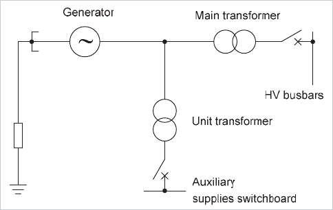
A unit transformer may be tapped off the interconnection
between generator and transformer for the supply of power to
auxiliary plant, as shown in Figure 17.1. The unit transformer
could be of the order of 10% of the unit rating for a large fossil-
fuelled steam set with additional flue-gas desulphurisation
plant, but it may only be of the order of 1% of unit rating for a
hydro set.
Figure 17.1: Generator-transformer unit
© 2011 Alstom Grid. Single copies of this document may be filed or printed for personal non-commercial use and must include this
copyright notice but may not be copied or displayed for commercial purposes without the prior written permission of Alstom Grid.
Network Protection & Automation Guide
17-2
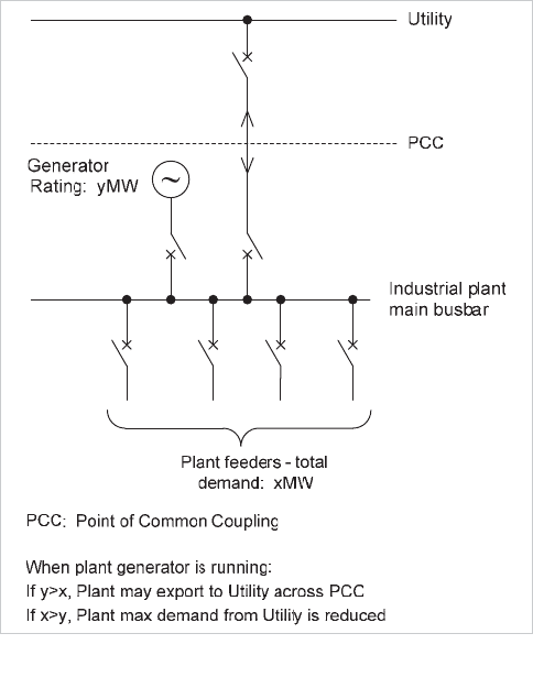
Industrial or commercial plants with a requirement for
steam/hot water now often include generating plant utilising
or producing steam to improve overall economics, as a
Combined Heat and Power (CHP) scheme. The plant will
typically have a connection to the public Utility distribution
system, and such generation is referred to as ‘embedded’
generation. The generating plant may be capable of export of
surplus power, or simply reduce the import of power from the
supply Utility. This is shown in Figure 17.2.
Figure 17.2: Embedded generation
A modern generating unit is a complex system comprising the
generator stator winding, associated transformer and unit
transformer (if present), the rotor with its field winding and
excitation system, and the prime mover with its associated
auxiliaries. Faults of many kinds can occur within this system
for which diverse forms of electrical and mechanical protection
are required. The amount of protection applied will be
governed by economic considerations, taking into account the
value of the machine, and the value of its output to the plant
owner.
The following problems require consideration from the point of
view of applying protection:
x stator electrical faults
x overload
x overvoltage
x unbalanced loading
x overfluxing
x inadvertent energisation
x rotor electrical faults
x loss of excitation
x loss of synchronism
x failure of prime mover
x lubrication oil failure
x overspeeding
x rotor distortion
x difference in expansion between rotating and stationary
parts
x excessive vibration
x core lamination faults
17.2 GENERATOR EARTHING
The neutral point of a generator is usually earthed to facilitate
protection of the stator winding and associated system.
Earthing also prevents damaging transient overvoltages in the
event of an arcing earth fault or ferroresonance.
For HV generators, impedance is usually inserted in the stator
earthing connection to limit the magnitude of earth fault
current. There is a wide variation in the earth fault current
chosen, common values being:
x rated current
x 200A-400A (low impedance earthing)
x 10A-20A (high impedance earthing)
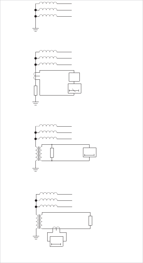
The main methods of impedance-earthing a generator are
shown in Figure 17.3. L
ow values of earth fault current may
limit the damage caused from a fault, but they simultaneously
make detection of a fault towards the stator winding star point
more difficult. Except for special applications, such as marine,
LV generators are normally solidly earthed to comply with
safety requirements. Where a step-up transformer is applied,
the generator and the lower voltage winding of the
transformer can be treated as an isolated system that is not
influenced by the earthing requirements of the power system.
© 2011 Alstom Grid. Single copies of this document may be filed or printed for personal non-commercial use and must include this
copyright notice but may not be copied or displayed for commercial purposes without the prior written permission of Alstom Grid.
Chapter 17 Generator and Generator Transformer Protection
17-3
Typical setting
(% of earthing
resistor rating)
10
5
Loading
resistor
(b) Resistance earthing
(c) Distribution transformer earthing
with overvoltage relay.
(d) Distribution transformer earthing
with overcurrent relay
(a) Direct earthing
resistor
Loading
I>
I>>
V>
I>
Figure 17.3: Methods of generator earthing
An earthing transformer or a series impedance can be used as
the impedance. If an earthing transformer is used, the
continuous rating is usually in the range 5-250kVA. The
secondary winding is loaded with a resistor of a value which,
when referred through the transformer ratio, will pass the
chosen short-time earth-fault current. This is typically in the
range of 5-20A. The resistor prevents the production of high
transient overvoltages in the event of an arcing earth fault,
which it does by discharging the bound charge in the circuit
capacitance. For this reason, the resistive component of fault
current should not be less than the residual capacitance
current. This is the basis of the design, and in practice values
of between 3-5 I
co
are used.
It is important that the earthing transformer never becomes
saturated; otherwise a very undesirable condition of
ferroresonance may occur. The normal rise of the generated
voltage above the rated value caused by a sudden loss of load
or by field forcing must be considered, as well as flux doubling
in the transformer due to the point-on-wave of voltage
application. It is sufficient that the transformer be designed to
have a primary winding knee-point e.m.f. equal to 1.3 times
the generator rated line voltage.
17.3 STATOR WINDING FAULTS
Failure of the stator windings or connection insulation can
result in severe damage to the windings and stator core. The
extent of the damage will depend on the magnitude and
duration of the fault current.
17.3.1 Earth Faults
The most probable mode of insulation failure is phase to earth.
Use of an earthing impedance limits the earth fault current and
hence stator damage.
An earth fault involving the stator core results in burning of the
iron at the point of fault and welds laminations together.
Replacement of the faulty conductor may not be a very serious
matter (dependent on set rating/voltage/construction) but the
damage to the core cannot be ignored, since the welding of
laminations may result in local overheating. The damaged
area can sometimes be repaired, but if severe damage has
occurred, a partial core rebuild will be necessary. A flashover is
more likely to occur in the end-winding region, where electrical
stresses are highest. The resultant forces on the conductors
would be very large and they may result in extensive damage,
requiring the partial or total rewinding of the generator. Apart
from burning the core, the greatest danger arising from failure
to quickly deal with a fault is fire. A large portion of the
insulating material is inflammable, and in the case of an air-
cooled machine, the forced ventilation can quickly cause an arc
flame to spread around the winding. Fire will not occur in a
hydrogen-cooled machine, provided the stator system remains
sealed. In any case, the length of an outage may be
considerable, resulting in major financial impact from loss of
generation revenue and/or import of additional energy.
17.3.2 Phase-Phase Faults
Phase-phase faults clear of earth are less common; they may
occur on the end portion of stator coils or in the slots if the
winding involves two coil sides in the same slot. In the latter
case, the fault will involve earth in a very short time. Phase
fault current is not limited by the method of earthing the
neutral point.
17.3.3 Interturn Faults
Interturn faults are rare, but a significant fault-loop current can
© 2011 Alstom Grid. Single copies of this document may be filed or printed for personal non-commercial use and must include this
copyright notice but may not be copied or displayed for commercial purposes without the prior written permission of Alstom Grid.
Network Protection & Automation Guide
17-4
arise where such a fault does occur. Conventional generator
protection systems would be blind to an interturn fault, but the
extra cost and complication of providing detection of a purely
interturn fault is not usually justified. In this case, an interturn
fault must develop into an earth fault before it can be cleared.
An exception may be where a machine has an abnormally
complicated or multiple winding arrangement, where the
probability of an interturn fault might be increased.
17.4 STATOR WINDING PROTECTION
To respond quickly to a phase fault with damaging heavy
current, sensitive, high-speed differential protection is normally
applied to generators rated in excess of 1MVA. For large
generating units, fast fault clearance will also maintain stability
of the main power system. The zone of differential protection
can be extended to include an associated step-up transformer.
For smaller generators, IDMT/instantaneous overcurrent
protection is usually the only phase fault protection applied.
Sections 17.5 to 17.8 detail the various methods that are
available for stator winding protection.
17.5 DIFFERENTIAL PROTECTION OF DIRECT
CONNECTED GENERATORS
The theory of circulating current differential protection is
discussed fully in Section 10.4.
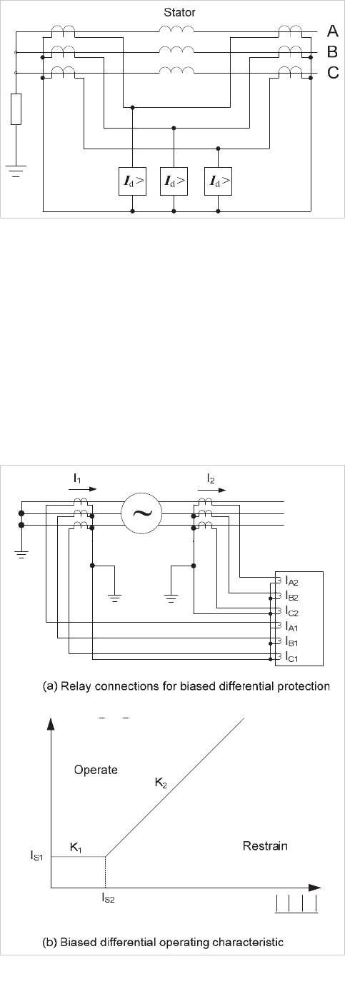
High-speed phase fault protection is provided, by use of the
connections shown in Figure 17.4. This depicts the derivation
of differential current through CT secondary circuit
connections. This protection may also offer earth fault
protection for some moderate impedance-earthed applications.
Either biased differential or high impedance differential
techniques can be applied. A subtle difference with modern,
biased, numerical generator protection relays is that they
usually derive the differential currents and biasing currents by
algorithmic calculation, after measurement of the individual CT
secondary currents. In such relay designs, there is full galvanic
separation of the neutral-tail and terminal CT secondary
circuits, as indicated in Figure 17.5(a). This is not the case for
the application of high-impedance differential protection. This
difference can impose some special relay design requirements
to achieve stability for biased differential protection in some
applications.
Figure 17.4: Stator differential protection
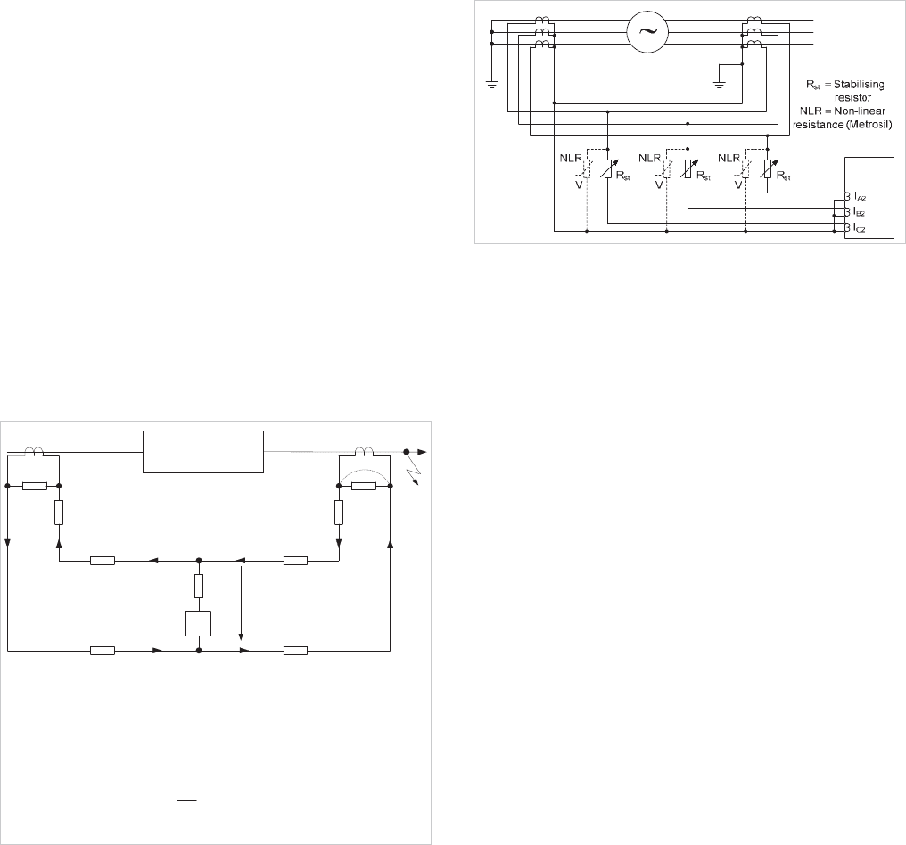
17.5.1 Biased Differential Protection
The relay connections for this form of protection are shown in
Figure 17.5(a) and a typical bias characteristic is shown in
Figure 17.5(b). The differential current threshold setting Is1
can be set as low as 5% of rated generator current, to provide
protection for as much of the winding as possible. The bias
slope break-point threshold setting Is2 would typically be set to
a value above generator rated current, say 120%, to achieve
external fault stability in the event of transient asymmetric CT
saturation. Bias slope K2 setting would typically be set at
150%.
2
21
II
I
bias
21
III
diff
Figure 17.5: Typical generator biased differential protection
© 2011 Alstom Grid. Single copies of this document may be filed or printed for personal non-commercial use and must include this
copyright notice but may not be copied or displayed for commercial purposes without the prior written permission of Alstom Grid.
Chapter 17 Generator and Generator Transformer Protection
17-5
17.5.2 High Impedance Differential Protection
This differs from biased differential protection by the manner in
which relay stability is achieved for external faults and by the
fact that the differential current must be attained through the
electrical connections of CT secondary circuits. If the
impedance of each relay in Figure 17.4 is high, the event of
one CT becoming saturated by the through fault current
(leading to a relatively low CT impedance), will allow the
current from the unsaturated CT to flow mainly through the
saturated CT rather than through the relay. This provides the
required protection stability where a tuned relay element is
employed. In practice, external resistance is added to the relay
circuit to provide the necessary high impedance. The principle
of high-impedance protection application is illustrated in
Figure 17.6, together with a summary of the calculations
required to determine the value of external stabilising
resistance.
V
r
R
st
R
L3
R
L4
R
L1
R
L2
R
CT1
R
CT2
I
f
Z
m
Healthy CT Saturated CT
Protected zone
Voltage across relay circuit
Stabilising resistor, R
st
, limits spill current to <I
s
(relay setting)
where R
R
= relay burden
s
st R
s
V
RR
I
I
d
>
rfCT L
VIR R2
and
sr
VKV
dwhere 1.0 K 1.5
Figure 17.6: Principle of high impedance differential protection
In some applications, protection may be required to limit
voltages across the CT secondary circuits when the differential
secondary current for an internal phase fault flows through the
high impedance relay circuit(s), but this is not commonly a
requirement for generator differential applications unless very
high impedance relays are applied. Where necessary, shunt–
connected, non-linear resistors, should be deployed, as shown
in Figure 17.7.
Figure 17.7: Relay connections for high impedance differential
protection
To calculate the primary operating current, the following
expression is used:
esop
nIINI u
1
where:
I
op
= primary operating current
N = CT ratio
I
s1
= relay setting
n = number of CTs in parallel with relay element
I
e
= CT magnetising current at V
S
I
s1
is typically set to 5% of generator rated secondary current.
It can be seen from the above that the calculations for the
application of high impedance differential protection are more
complex than for biased differential protection. However, the
protection scheme is actually quite simple and it offers a high
level of stability for through faults and external switching
events. With the advent of multi-function numerical relays
and with a desire to dispense with external components, high
impedance differential protection is not as popular as biased
differential protection in modern relaying practice.
17.5.3 CT Requirements
The CT requirements for differential protection will vary
according to the relay used. Modern numerical relays may not
require CTs specifically designed for differential protection to
IEC 60044-1 class PX (or BS 3938 class X). However,
requirements in respect of CT knee-point voltage will still have
to be checked for the specific relays used. High impedance
differential protection may be more onerous in this respect
than biased differential protection. Many factors affect this,
including the other protection functions fed by the CTs and the
knee-point requirements of the particular relay concerned.
Relay manufacturers are able to provide detailed guidance on
this matter.
© 2011 Alstom Grid. Single copies of this document may be filed or printed for personal non-commercial use and must include this
copyright notice but may not be copied or displayed for commercial purposes without the prior written permission of Alstom Grid.
Network Protection & Automation Guide
17-6
17.6 DIFFERENTIAL PROTECTION OF
GENERATOR-TRANSFORMERS
A common connection arrangement for large generators is to
operate the generator and associated step-up transformer as a
unit without any intervening circuit breaker. The unit
transformer supplying the generator auxiliaries is tapped off
the connection between generator and step-up transformer.
Differential protection can be arranged as follows.
17.6.1 Generator/Step-up Transformer Differential
Protection
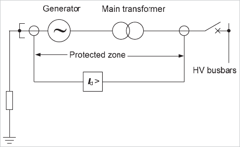
The generator stator and step-up transformer can be protected
by a single zone of overall differential protection (Figure 17.8).
This will be in addition to differential protection applied to the
generator only. The current transformers should be located in
the generator neutral connections and in the transformer HV
connections. Alternatively, CTs within the HV switchyard may
be employed if the distance is not technically prohibitive. Even
where there is a generator circuit breaker, overall differential
protection can still be provided if desired.
Figure 17.8: Overall generator-transformer differential protection
The current transformers should be rated according to Section
16.8.2. Since a power transformer is included within the zone
of protection, biased transformer differential protection, with
magnetising inrush restraint should be applied, as discussed in
Section 16.8.5. Transient overfluxing of the generator
transformer may arise due to overvoltage following generator
load rejection. In some applications, this may threaten the
stability of the differential protection. In such cases,
consideration should be given to applying protection with
transient overfluxing restraint/blocking (e.g. based on a 5
th
harmonic differential current threshold). Protection against
sustained overfluxing is covered in Section 17.4.
17.6.2 Unit Transformer Differential Protection
The current taken by the unit transformer must be allowed for
by arranging the generator differential protection as a three-
ended scheme. Unit transformer current transformers are
usually applied to balance the generator differential protection
and prevent the unit transformer through current being seen
as differential current. An exception might be where the unit
transformer rating is extremely low in relation to the generator
rating, e.g. for some hydro applications. The location of the
third set of current transformers is normally on the primary
side of the unit transformer. If located on secondary side of
the unit transformer, they would have to be of an exceptionally
high ratio, or exceptionally high ratio interposing CTs would
have to be used. Thus, the use of secondary side CTs is not to
be recommended. One advantage is that Unit Transformer
faults would be within the zone of protection of the generator.
However, the sensitivity of the generator protection to unit
transformer phase faults would be considered inadequate, due
to the relatively low rating of the transformer in relation to that
of the generator. Thus, the unit transformer should have its
own differential protection scheme. Protection for the Unit
Transformer is covered in Chapter 16, including methods for
stabilising the protection against magnetising inrush
conditions.
17.7 OVERCURRENT PROTECTION
Overcurrent protection of generators may take two forms.
Plain overcurrent protection may be used as the principal form
of protection for small generators, and back-up protection for
larger ones where differential protection is used as the primary
method of generator stator winding protection. Voltage
dependent overcurrent protection may be applied where
differential protection is not justified on larger generators, or
where problems are met in applying plain overcurrent
protection.
17.7.1 Plain Overcurrent Protection
It is usual to apply time-delayed plain overcurrent protection to
generators. For generators rated less than 1MVA, this will
form the principal stator winding protection for phase faults.
For larger generators, overcurrent protection can be applied as
remote back-up protection, to disconnect the unit from any
uncleared external fault. Where there is only one set of
differential main protection, for a smaller generator, the
overcurrent protection will also provide local back-up
protection for the protected plant, in the event that the main
protection fails to operate. The general principles of setting
overcurrent relays are given in Chapter 9.
In the case of a single generator feeding an isolated system,
current transformers at the neutral end of the machine should
energise the overcurrent protection, to allow a response to
winding fault conditions. Relay characteristics should be
selected to take into account the fault current decrement
behaviour of the generator, with allowance for the
© 2011 Alstom Grid. Single copies of this document may be filed or printed for personal non-commercial use and must include this
copyright notice but may not be copied or displayed for commercial purposes without the prior written permission of Alstom Grid.
