Water and Wastewater Engineering
Подождите немного. Документ загружается.


HEADWORKS AND PRELIMINARY TREATMENT 20-41
h . The mass of BOD
5
entering the equalization basin is the product of the inflow ( Q ), the
concentration of BOD
5
( S
0
), and the integration time ( t ):
M Q S t
BOD-in
()( )( )
0
The mass of BOD
5
leaving the equalization basin is the product of the average outflow
( Q
avg
), the average concentration ( S
avg
) in the basin, and the integration time ( t ):
M Q S t
BOD-ou t avg avg
()()()
The average concentration is determined as:
S
SS
i s
i s
avg
prev
()()()( )
0
V V
V V
where
i
volume
V
of inflow during time interval t, m
3
S
0
average BOD
5
concentration during time interval t, g/m
3
s
volume
V
of wastewater in the basin at the end of the previous time
interval t, m
3
S
prev
concentration of BOD
5
in the basin at the end of the previous time
interval t, g/m
3
i. Noting that 1 mg/L 1 g/m
3
, find that the first row (0900 h time) computations in col-
umns 8, 9, and 10 are
M
BOD-in
m /s g/m h ()()()(00631 140 1 3 600
33
.,ss/h kg/g kg
m
avg
)( )
()(
10 318
227 16 14
3
3
.
.
S
000
227 16 0
140
00
3
3
3
g/m
m
g/m
BOD-out
)
(
.
.
+
M 55657 140 1 3 600 10
33 3
m /s g/m h s/h)( )( )( )(,
kkg/g kg) 28 5.
Note that the zero values in the computation of S
avg
are valid only at start-up of an empty
basin. Also note that in this case MBOD-in and MBOD-out differ only because of the
difference in flow rates.
j. For the second row (1000 h), the computations are
M
BOD-in
m /s g/m h ()()()(0 0670 15013 600
33
.,ss/h kg/g kg
m
avg
)( )
()(
10 362
241 2 150
3
3
.
.
S
g/mmg/m
m
333
3
23 51 140
241 2 23 51
)( )( )
.
..
mm
mg/L
m /s
BOD-out
3
3
149 11
005657 149
.
..M ()(111 1 3 600 10 30 37
33
g/m h s/h kg/g)( )( )( ),.
kkg
Note that
s
V
is the volume of wastewater in the basin at the end of the previous time
interval. Therefore, it is equal to the accumulated dS. The concentration of BOD
5
( S
prev
)
is the average concentration at the end of previous interval ( S
avg
) and not the influent
concentration for the previous interval ( S
0
).
20-42 WATER AND WASTEWATER ENGINEERING
k. For the third row (1100 h), the concentration of BOD
5
is
S
avg
m g/mm
()()()(24552155 61 06 149 1
33 3
...11
245526106
153 83
3
33
g/m
mm
mg/L
)
..
.
l. The ratio of the maximum BOD mass to the minimum BOD mass drops from
5623 215 26 15 1.:. .:kg kg or
to
33 97 18 55 183 1.:. .:kg kg or
Comments:
1 . The BOD calculations assume a completely mixed basin.
2. The volume accumulation at the end of the diurnal cycle is unlikely to be exactly zero
because the diurnal flow pattern is not a perfectly symmetrical sinusoidal curve. There-
fore, the pumping rate out of the equalization basin cannot be con
stant.
Basin Geometry. If the basin configuration is for in-line equalization, the geometry should
allow the basin to function as a continuous flow stirred tank reactor. This implies that long rect-
angular basins should be avoided, and inlet and outlet locations should be chosen to minimize
short circu
iting. In particular, the inlet should discharge near the mixing equipment.
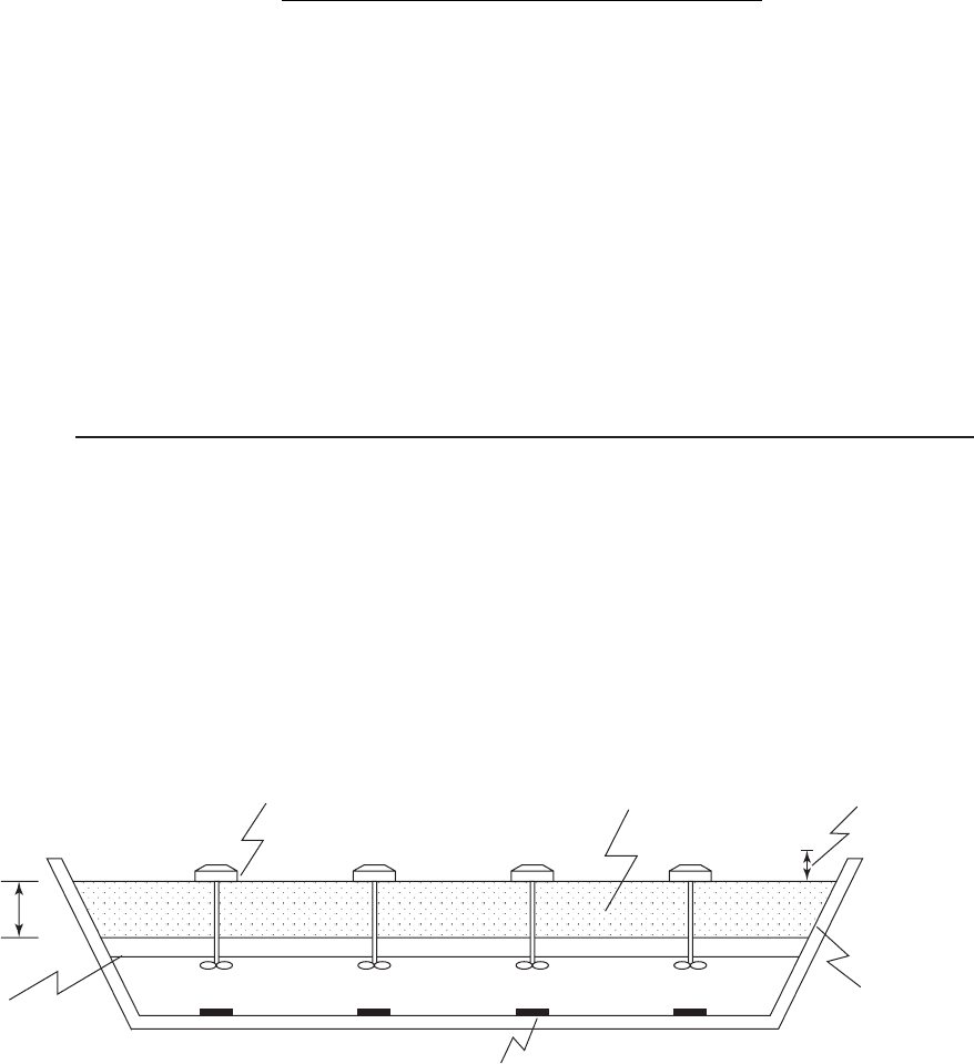
Earth basins with an impermeable liner are generally the least expensive ( Figure 20-17 ). The
slopes vary between 3:1 and 2:1. The minimum water depth is dependent on the type of aeration
equipment, but typically is in the range of 1.5 to 2 m. The upper level of the embankment may
nee
d to be protected from wind-induced erosion. The top of the embankment should be wide
enough to facilitate vehicle maneuvering. Fencing must be provided to prevent public access.
Aerator
Effective basin
volume
1m freeboard
HDPE
lining
Concrete erosion pad
Minimum allowable
liquid level to
protect aerator
Working
volume
FIGURE 20-17
Equalization basin geometry for an earthen basin.

HEADWORKS AND PRELIMINARY TREATMENT 20-43
The bas ins may also be made out of concrete and in rare instances, out of steel. Concrete
construction can minimize space requirements. If the plant is near neighborhoods, the basin can
be covered to minimize odor complaints.
Mixing and Air Requirements. Both in-line and off-line equalization basins require mixing.
Adequate aeration and mixing must be provided to prevent odors and solids deposition. Mechani-
cal aerators and diffused aeration have been used to supply mixing and aeration.
The diffused aeration systems should provide 1.8 to 2.9 m
3
of air/h · m
3
of storage for mix-
ing. They should use either coarse or intermediate bubble diffusers. The fine bubble diffusers
tend to clog in this application. Because of the variation in depth over the operating cycle, pres-
sure regulation should be considerred in the design of the blower system. For example, positive
displa
cement (PD) blowers are self-regulating. Others m ust have pressure regulator controls.
The air supply should be isolated from other treatment plant aeration requirements to facilitate
process aeration control (GLUMRB, 2004).
Mechanical mixing requirements for municipal wastewater with suspended solids concentra-
tions on the order of 200 mg/L range fro
m 0.004 to 0.008 kW/m
3
of storage. To maintain aerobic
conditions, air should be supplied at rate of 0.6 to 0.9 m
3
/h · m
3
of storage (WEF, 1998).
The oxygen transfer efficiency of mechanical aerators is lower in wastewater than in tap
water und er standard c onditions. A reasonable assumption for ox ygen transfer efficiency for
equalization basin design is 0.16 to 0.39 kg/MJ (WEF, 1998).
In earthen basins, a concrete pad is placed beneath mechanical aerators to prevent erosion of
the botto
m. The aerators may be either floating or pedestal mounted. The aerators must have a
low-level shutoff in case the wastewater level is drawn below the minimum operating level.
Mechanical aerator selection is made from manufacturer’s data similar to that provided in
Table 20-13 and Figure 20-18 . Example 20-7 illustrates the
selection process.
TABLE 20-13
Selection table for floating mechanical aerators
a
a
These aerators are representative but do not represent actual choices. Actual manufacturers’
data must be used for real world design.
b
OTR oxygen transfer rate
Size, kW
OTR
b
,
kg/MJ
Nominal operating,
depth, m
Complete
mix zone,
m
Complete
O
2
dispersion zone,
m
0.75 0.20 1.8 6 20
1.5 0.23 1.8 8 30
2.5 0.23 1.8 12 45
3.5 0.23 1.8 14 50
5.5 0.22 2.4 1550
7.5 0.20 3.0 1555
10 0.21 3.0 19 60
15 0.19 3.0 22 70
20 0.20 3.0 24 80
25 0.21 3.0 26 85
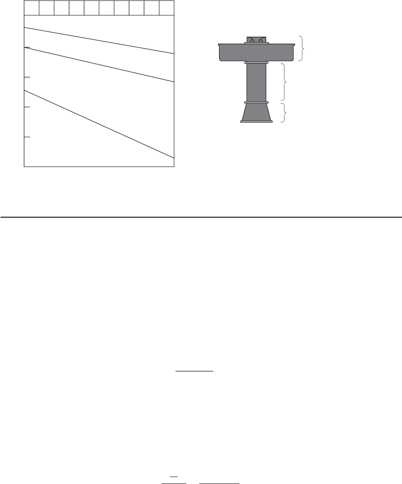
20-44 WATER AND WASTEWATER ENGINEERING
Normal operation
Aerator assembly
Draft tube required
Wastewater depth, m
5.0
4.0
3.0
2.0
1.0
Antierosion assembly
required
Too shallow
0.75 1.5 2.53.55.5 7.5 10 15 20 25
Unit size, kW
Draft tube
Intake cone
FIGURE 20-18
Floating aerator depth requirements and an illustration of a draft tub.
Example 20-7. Select an appropriate aerator and aerator configuration for the equalization
basin volume calculated in Example 20-6 . Assume that the aerators in Table 20-13 are available
and that Figure 20-18 applies.
Solution:
a . From Example 20-6 , the required storage volume is 1,080 m
3
. Using the low end of the
recommended range for mixing, estimate the total power required.
Power kW/mm kW()()0 004 1 080 4 32
33
.,.
b. Assume four aerators will be used. Each aerator must supply
4 32
4
108
.
.
kW
kW
c. From Table 20-13 , the smallest size that will supply enough power is the 1.5 kW aerator.
Use this aerator as a first trial.
d. From Table 20-13 , the nominal operating depth is 1.8 m. From Figure 20-18 , the range
of depths for normal operation is from 1.2 to 2.9 m. Use a depth of 2.9 m to estimate the
surface area of the equalization basin.
A
depth
m
m
m
1 080
29
372 41
3
2
,
.
.
V
e. Assume a square equalization basin and compute the dimensions.
Length mm
/
()372 41 19 30
212
..
HEADWORKS AND PRELIMINARY TREATMENT 20-45
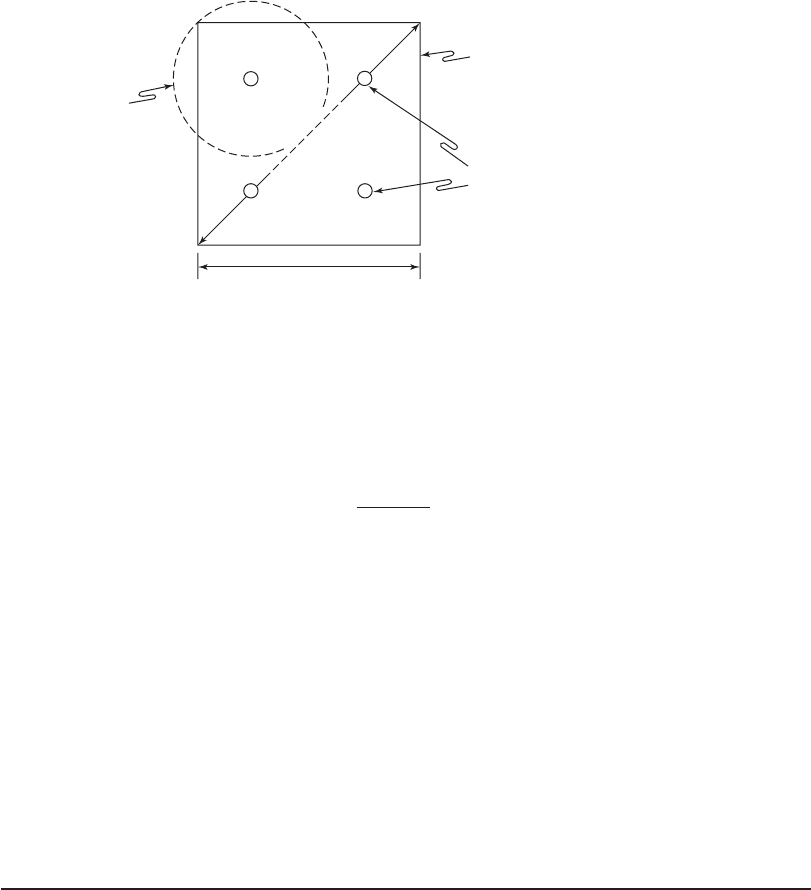
f. Assume each aerator is placed in one quadrant as shown in the sketch below.
Aerators
27.29
m
19.30 m
Zone of
complete mix for
3.5 kW aerator
Aeration basin
perimeter
g. The diagonal across the equalization basin is the hypotenuse of the triangle formed by
the sides. The length of the hypotenuse is
L
hypotenuse
/
m [( ) ( ) ]19 3019302729
2212
.. .
h. Check the zone of complete mixing. The specified complete mix zone is 8 m for the 1.5 kW
aerator. With the aerator placed in the center of the quadrant as shown above, this aerator
must completely mix a diameter of
27 29
2
13 64
.
.
m
m
if there are to be no dead spots. Therefore, a larger aerator is required.
i. For another trial, select a 3.5 kW aerator as it has a complete mix zone of 14 m.
j. Check the depth. From Figure 20-18 , the depth is satisfactory for the 3.5 kW aerator.
Comments:
1 . Multiple aerators are selected to provide redundancy.
2. Alternate sol
utions that require less power are possible, but power requirements to pre-
vent the deposition of solids may be greater than that required for blending. The actual
power supplied from the four large aerators is 0.013 kW/m
3
.
3. Because the envelope for complete mixing is fixed by the diagonal, the zone of complete
mixing of each aerator will overlap the edges of the basin. This may present erosion
problems.
Appurtenances. The following appurtenances are provided to facilitate operation of the equal-
ization basin: (1) hose facilities for flushing grease and solid s from the basin walls, (2) a high-
water takeoff to remove s
cum, (3) a spray system to reduce foam, (4) a bypass so that the bas in
may be dewatered for maintenance, and (5) a basin flushing system to remove sediment. If odors
are of concern, then a covered basin with appropriate odor control should be provided.
Pumps. Low-head pump
s may be required to carry the wastewater to downstream processes.
20-46 WATER AND WASTEWATER ENGINEERING
20-8 ALTERNATIVE PRELIMINARY PROCESS ARRANGEMENTS
There are a large number of arrangements for the preliminary treatment processes that will
prove satisfactory. These are d ependent on both the upstream and downstream processes that
are employed. Combined sewage requ ires both a higher degree of processing and more rugged
equipment than domestic sewage. The
use of membrane treatment technology and/or fine bubble
diffusers will require higher efficiency in removing inert solids.
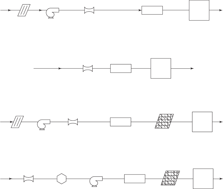
Figure 20-19 illustrates a number of alternatives that have been employed. The list is not all-
inclusive.
Bar
rack
Pump Flow
measurement
Grit
chamber
Equalization
basin
Conventional arrangement for force main flow with bar rack at lift station
Conventional arrangement for gravity flow combined sewer
Membrane system downstream; gravity flow combined sewer
Flow
measurement
Grit
chamber
Equalization
basin
Macerator Pump
Flow
measurement
Fine
screen
Grit
chamber
Equalization
basin
Membrane system downstream; force main with bar rack at lift station
Bar
rack
Pump Flow
measurement
Equalization
basin
Fine
screen
Grit
chamber
FIGURE 20-19
E xamples of some alternative arrangements of preliminary treatment processes.

HEADWORKS AND PRELIMINARY TREATMENT 20-47
20-9 CHAPTER REVIEW
When you have completed studying this chapter, you should be able to do the following without
the aid of your textbook or notes:
1 . Explain the circumstances that favor the use of a screw pump or centrifugal pump in
the headworks.
2. Explain the circumstances that favor the use of a Parshall flume or magnetic flow meter
in the headworks.
3. Given a list of hydraulic capacities for a was
tewater treatment plant, select the appro-
priate one for headworks processes.
4. Select an appropriate screen opening size given a description of the upstream and
downstream processes and a list of available sizes.
5. Draw a sketch of the arrangement of channels for bar screens noting the method of iso-
lation and approach distances as a fu
nction of depth of flow.
6. Discuss the philosophy of the use of coarse solids reduction versus the use of screens.
7. Sketch the cross section of an aerated grit chamber and label the longitudinal baffle,
aeration header, and the critical dimension that controls the velocity across the bottom
of the chamber.
8. Define SES an
d explain why it is a better criterion for grit removal than a sand
particle.
9. Using a sketch you have drawn, show a class how an equalization basin dampens flow
variations.
W ith the aid of this text, you should be able to do the following:
10. Design a screw pump system given the elevations and range of flow rates.
11. Select an appropriate Parshall flume given the range of flow rates and deter
mine the
depth of the flume.
12. Design the channel for a bar rack given the width to accommodate the screen.
13. Design a bar rack and estimate the headloss given an assumption about the allowable
percent blockage before activation of the cleaning equipment.
14. Design an aerated grit chamber to remove a particle with a given SES.
15. Determine the volume of an equalization basin given the diurnal flow pattern.
16. Select an appropriate aeration sys
tem for a given volume of equalization basin.
Visit the text website at www.mhprofessional.com/wwe for supplementary materials
and a gallery of photos.
20-48 WATER AND WASTEWATER ENGINEERING
20-10 PROBLEMS
20-1. Using the pumps given in Table 20-1 , design a screw pump system for the town of
Pigeonroost using the following assumptions:
Interceptor sewer
Minimum sewage elevation 41.91 m
M a ximum sewage elevation 42.21 m
D i scharge elevation to stilling well 46.11 m
Average fl ow at design life 16,000 m
3
/ d
Peaking factor for peak hour 2.62
Ratio factor for minimum fl ow at beginning of design life 0.49
Complete the design by providing the following: pump specifications (diameter,
number of flights), number of pumps, and a sketch of the plan view with dimensions
(assume the width of each pump equals the diameter of the sc
rew plus 0.6 m).
20-2. Using the pumps given in Table 20-1 , design a screw pump system for the village of
Fishkill using the following assumptions:
Interceptor sewer
Minimum sewage elevation 112.60 m
M a ximum sewage elevation 112.80 m
D i scharge elevation to stilling well 116.40 m
Average flow at design life 8,600 m
3
/ d
Peaking factor for peak hour 2.8
Ratio factor for minimum flow at beginning of design life 0.49
Complete the design by providing the following: pump specifications (diameter,
number of flights), number of pumps, and a sketch of the plan view with dimensions
(assume the width of each pump equals the diameter of the screw pl
us 0.6 m).
20-3. The manufacturer of the screw pumps listed in Table 20-1 has rated the pumps at an
angle of 38 to shorten the footprint and increase the lift. The rating downsizes the
flow rate by a factor of 0.71 and increases the head available by a factor of 1.4.
Rework Problem 20-1 with the new ratings for the screw pumps.
Complete the design by provid
ing the following: pump specifications (diameter,
number of flights), number of pumps, sketch of the plan view with dimensions
(assume the width of each pump equals the diameter of the screw plus 0.6 m).
20-4. The manufacturer of the screw pumps listed in Table 20-1 has rated the pumps
at an
angle of 38 to shorten the footprint and increase the lift. The rating downsizes the
flow rate by a factor of 0.71 and increases the head available by a factor of 1.4.
Rework Problem 20-2 with the new ratings for the screw pumps.
Complete the design by providing the following: pump specifications (diameter,
number of flights), number of pumps, sketch of the plan view with dim
ensions
(assume the width of each pump equals the diameter of the screw plus 0.6 m).
20-5. Using the data for the town of Pigeonroost ( Problem 20-1 ), select a Parshall flume
from the options available in Table 20-2 . Identify the selection by the throat width.
Determine the depth of the flume if 0.6 m of freeboard is to be provided.
HEADWORKS AND PRELIMINARY TREATMENT 20-49
20-6. Using the data for the village of Fishkill ( Problem 20-2 ), select a Parshall flume from
the options available in Table 20-2 . Identify the selection by the throat width. Deter-
mine the depth of the flume if 0.6 m of freeboard is to be provided.
20-7. The preliminary design using a Parshall flume and screw pump for the town of
Pigeonroost’s WWTP ( Problems 20-1 and 20-5 ) resulte
d in too much space. An
alternative design calls for a pump to lift the sewage and a magnetic flow meter to
measure the flow. Assuming that the velocity in the pipe is to be about 1 m/s,
perform a web search to locate an appropriate magnetic flow meter. The flow meter
must fit in one of the following standard pipe sizes (all in mm): 100, 125, 150, 200,
250, 300, 350, 375, 400.
20-8.
The Parshall flume and screw pump for the village of Fishkill’s’s WWTP ( Problems
20-2 and 20-6 ) resulted in too much space. An alternative design calls for a pump to
lift the sewage and a magnetic flow meter. Assuming that the velocity in the pipe is
to be about 1 m/s, perform a web search to locate an appropriate magnetic flow
meter. The flow meter must fit in one of the following stand
ard pipe sizes (all in
mm): 100, 125, 150, 200, 250, 300, 350, 375, 400.
20-9. Continuing the design of preliminary treatment facilities for the town of Pigeonroost
WWTP ( Problem 20-1 ), design a bar rack channel using an inlet channel width of
0.68 m, a slope of 0.00025, and the assumptions used in Example 20-3 . Assume
0.6 m of freeboard is to be provid
ed.
20-10. Continuing the design of preliminary treatment facilities for the village of Fishkill
WWTP ( Problem 20-2 ), design a bar rack channel using an inlet channel width of
0.84 m, a slope of 0.00050 and the assumptions used in Example 20-3 . Assume 0.6 m
of freeboard is to be provided.
20-11. Continuing the design of preliminary treatment fac
ilities for the town of Pigeon-
roost’s WWTP ( Problem 20-1 ), estimate the headlosses for a bar rack using an inlet
channel width of 0.68 m and the assumptions used in Example 20-4 .
20-12. Continuing the design of preliminary treatment facilities for the village of Fishkill
WWTP ( Problem 20-2 ), estimate the headlosses for a bar rack using using an inlet
channel width of 0.84 m and the assu
mptions used in Example 20-4 .
20-13. Keller et al. (2006) reported that fine screens with 3 mm openings have approxi-
mately 35% effective open area. Estimate the headloss for a flow rate of 16,000 m
3
/ d
through a 3.2 m
2
clean fine screen with 3 mm openings.
20-14. Keller et al. (2006) reported that fine screens with 1 mm openings have approxi-
mately 31% effective open area. Estimate the headloss for a flow rate of 8,600 m
3
/ d
through a 1.6 m
2
clean fine screen with 3 mm openings.
20-15. Using Newton’s equation ( Equation 20-8 ) and Camp’s scour equation ( Equation 20-9 ),
demonstrate that a grit particle with a diameter of 200 m and a specific
gravity of 2.65 results in a design overflow rate of 0.021 m/s and a horizontal velocity
greater than 0.056 m/s and less than 0.23 m/s for an horizontal flow grit
chamber if the
organic particles of the same size have a specific gravity of 1.10. Assume 0.06
and f 0.03.

20-50 WATER AND WASTEWATER ENGINEERING
20-16. Continuing the design of preliminary treatment facilities for the town of Pigeon-
roost’s WWTP ( Problem 20-1 ), design an aerated grit chamber. Use Albrecht’s
equation and assume a slot velocity of 0.15 m/s is required to achieve removal
of the design SES. Assume the sewers are separated and use a worst case
situation
for the design of the grit channel. To complete the design, specify the air supply
rate and provide a sketch of the cross section with dimensions.
20-17. Continuing the design of preliminary treatment facilities for the village of Fishkill
WWTP ( Problem 20-2 ), design an aerated grit chamber. Use Albrecht’s equation and
assume the required bottom velocity must achieve removal of a 60 m SES particle.
Assume the sewers are separated and use a worst case situation for the design of the
grit channel. To complete the design, specify the air supply rate and provide a sketch
of the cross section with dimensions
.
20-18. A treatment plant being designed for Cynusoidal City requires an equalization basin
to even out flow and BOD variations. The average daily flow is 0.400 m
3
/ s. The
following flows and BOD
5
have been found to be typical of the average variation
over a day . What volume equalization basin is required to provide for a uniform
outflow equ al to the average daily flow? Assume the flows are hourly averages and
that an addition of 25% to the estimated volume will be provided to account for
contingencies .
Time Flow, m
3
/s BOD
5
, mg/L Time Flow, m
3
/s BOD
5
, mg/L
0000 0.340 123 1200 0.508 268
0100 0.254 118 1300 0.526 282
0200 0.160 95 1400 0.530 280
0300 0.132801500 0.552 268
0400 0.13285 1600 0.570 250
0500 0.140 95 1700 0.596 205
0600 0.160 100 1800 0.604 168
0700 0.254 118 1900 0.570 140
0800 0.360 136 2000 0.552130
0900 0.446 170 2100 0.474 146
1000 0.474 220 2200 0.412 158
1100 0.482 2502300 0.372 154
20-19. A treatment plant being designed for Metuchen requires an equalization basin to even
out flow and BOD variations. The following flows and BOD
5
have been found to be
typical of the average variation over a day. What volume of equalization basin is
required to provide for a uniform outflow equal to the average daily flow? Assume
the flows are hourly averages and that an addition of 25% to the estimated volume
will be provided to account for contingencies.