Water and Wastewater Engineering
Подождите немного. Документ загружается.

HEADWORKS AND PRELIMINARY TREATMENT 20-31
bulb shape to provide this geometry (see, for example, the cross sections for Gdansk and Gdynia
in Poland—Sawicki, 2004), the complex ity of the shape would appear to be very expensive to
construct. The more conventional approach is to use dimensions and dimensional ratios that have
proven succe
ssful.
There is no typical geometry. Chambers have depths of 2 to 5 m. The width to liquid depth
ratio ranges from 1:1 to 5:1 with a typical value of 2:1. The length-to-width ratio ranges from
2.5:1 to 5:1 (WEF, 1998). Lengths range from 7.5 to 27.5 m (Metcalf & Eddy, 2003, Morales and
Reinhart, 1984).
Square chambers are not recommended. They req
uire careful placement of baffles to work
properly without short circuiting. Long, narrow tanks appear to provide the best process effi-
ciency, grit quality, and ease of operation (Morales and Reinhart, 1984).
Baffles. Four types of baffles have been used in aerated grit chambers: inlet, outlet, intermediate,
and longitudinal. The first three types of baffle are used to prevent short cir
cuiting of the flow through
the tank. The longitudinal baffle is used in conjunction with the air supply to control the roll pattern.
If the flow enters the chamber perpendicular to the flow through a long, narrow tank
( Figure 20-12 ), inlet and outlet baffles may not be required. The common use of inlet and outlet
baffles is to turn the direction of flow to induce a spiral roll and reduce short circuiting. The baf-
fle
s are placed perpendicular to the spiral roll pattern (Morales and Reinhart, 1984; WEF, 1998).
WEF (1998) suggests that a good design should include an intermediate baffle across the
width of the tank to prevent short circuiting through the center of the roll pattern.
The longitudinal baffle ( Figure 20-14 ) is placed approximately 1 m from the wall next
to the air diffusers (WEF
, 1998). It is an essential ingredient in controlling the roll pattern and
velocity of the flow across the bottom of the tank. The dimension d
b
i s sized to achieve a design ve-
locity across the bottom of the tank. Neither d
b
nor d
T
have been specified in the literature. Albrecht
(1967) proposed an empirical method for determining the velocity through the slot at the bottom of
the baffle. It includes selection of a design value for d
b
. This is discussed later in this section.
Air Supply. The shape of the grit chamber is not the only key to good design; diffuser place-
ment, air source, and adequate baffling all affect performance (Morales and Reinhart, 1984).
Coarse bubble diffusers are recommended for supplying the air. They are typically pla
ced 0.6 to
1 m above the bottom of the chamber. The air supply should be isolated from other treatment
plant aeration requirements to facilitate process control. The plant process air supply may provide
the air, but separate dedicated blowers are preferred (WEF, 1998). Adequate control, inc luding
valves and flow meters for each bank of
diffusers, is essential. In order to maintain effective grit
removal over a wide range of flows and grit loadings, the operators must be able to adjust the
aeration rate over a wide range of air flow rates and to taper the aeration rate along the tank.
The air supply and control system should be able to provide air over the range 0.0019 to
0.0125 m
3
/ s · m of tank length (GLUMRB, 2004; Sawaki, 2004; WEF, 1998).
Velocities. Unlike the horizontal-flow grit chamber, neither the overflow rate nor the velocity of
flow through the tank are design criteria. The primary design criterion for the aerated grit chamber
is the velocity of flow across the bottom of the tank (Albrecht, 1967; Sawicki, 2004). This veloc-
ity controls the SES diameter particle that will be removed. Based on theoretical calculations and
experimental evi
dence, for efficient removal of grit the velocity across the bottom of the tank
should be less than 0.15 m/s (Sawicki, 2004). Other experimental evidence is that a range of 0.03
to 0.40 m/s for the bottom velocity provides efficient removal (Morales and Reinhart, 1984).
20-32 WATER AND WASTEWATER ENGINEERING
WEF (1998) recommends that the velocity measured 150 mm below the surface be tapered
from 0.6 m/s at the inlet to 0.45 m/s at the tank outlet.
Because the geometry of the tank is fixed by the design, the only mechanism available for the
operator to control the velocity is to adjust the air flow rate. Thus, not only is it imperative that
operational control and fle
xibility be provided, but it is also advisable that a means of measuring
the velocity be made available. Morales and Reinhart (1984) used a portable water current meter
for their observations.
Quantities and Characteristics of Grit. The type of sewer system (separate or combined), and
characteristics of the drainage area, including soil type, industry t
ype, use of garbage grinders,
and so on, will affect both the quantity and charac ter of the grit. Based on U.S. EPA data, the
range in grit quantities varies from 0.004 to 0.037 m
3
/1000 m
3
of wastewater for separate sewers
and from 0.004 to 0.18 m
3
/1000 m
3
for combined sewers.
Grit solids content will vary from 35 to 80 percent with a volatile content of 1 to 55 percent
(U.S. EPA, 1979). Grit from a properly operating aerated grit chamber should have a volatile
content no greater than 10 percent (Imhoff and Imhoff, 1979; Sawicki, 2004). The moisture and
volatile content is influenced by the efficiency of washing.
Grit Sump. The volume of the grit sump at the bottom of the grit
chamber should be designed
based on the anticipated maximum load, efficiency of collection, and grit removal frequency. The
failure of grit removal systems often is not a fu nction of the sedimentation of the particles, but
rather the inability of the removal equipment to keep up with the load. As a result, settled
grit is
scoured out of the grit chamber.
The sump side walls are set at a steep angle. Angles of 60 to 90 from the horizontal are
shown in the literature.
Grit Removal Equipment. The four methods of removing grit from the sump are: inclined
screw or tubular conveyors, chain and bucket elevators, clamshell buckets, and pumping. Cu
r-
rently, chain and bucket systems are seldom installed. They will not be discussed here.
The inclined screw or tubular conveyors may provide some washing of the grit as it is removed.
These systems discharge a very dry grit (Morales and Reinhart, 1984). The
y have a relatively large
footprint and are sensitive to wear. The motor must be sized to handle sudden high peak loads.
Clamshell buckets are moved by an overhead crane. This system provides inconsistent grit
removal and requires discontinuing flow to the chamber during grit removal. It lacks effective
dewatering and was
hing.
P umping systems offer the advantage of a small footprint. However, the piping and valves
require intensive maintenance. In partic ular, the piping may become plugged. Dislodging the
compacted grit is a major undertaking.
Residuals Management. The design practice for treating and disposing of grit is discussed in
Chapter 27.
Design Criteria for Aerated Grit Chambers. Table 20-11 summ
arizes the design criteria for
aerated grit chambers.
Design Tools. Based on the theoretical concept that energy delivered to the liquid by air bub-
bles is equal to the local work performed by each bubble, Sawicki (2004) developed a method
for determining the transverse c irculation in the aerated grit chamber. This equation is solve
d

HEADWORKS AND PRELIMINARY TREATMENT 20-33
TABLE 20-11
Typical design criteria for aerated grit chambers
Parameter Typical range Comment
Detention time at
peak flow rate
120–300 s Typical 180 s
Dimensions
Depth 2–5 m Liquid depth
Width 2.5–7 m
Width:depth 1:1–5:1 Typical 1.5:1
Length 7.5–27.5 m
Length:width 2.5:1–5:1
Baffles
Inlet and outlet Required when flow enters parallel
to tank
Placed perpendicular to spiral roll
Intermediate Across width
Longitudinal Placed 1 m from wall
Air supply
Flow rate 0.0019–0.0125 m
3
/s · m Adjustable over full range
Diffuser 0.6–1 m above bottom Coarse bubble
Velocities
Transverse roll 0.6–0.45 m/s Tapered, measured 150 mm below
surface
Across bottom 0.03–0.45 m/s Measured at bottom of longitudinal
baffle
Quantity of grit 0.004–0.20 m
3
/1,000 m
3
of flow
Sources: Morales and Reinhart, 1984; Metcalf & Eddy, 2003; Sawicki, 2004; WEF, 1998.
n umerically to determine the circulation discharge. This can then be used to estimate the trajec-
tories of individual grit particles.
Computational fluid dynamics (CFD) modeling has been used to evaluate and optimize alter-
native baffle arrangements in the design of aerated grit chambers (Burbano, et al., 2009).
Albrecht (1967) developed an empirical equation that, except for the lack of a definitive
value for the empirical constant ( K ), can be helpful in exploring alternative designs. It provides a
means of estimating the velocity across the bottom of the chamber:
v
SA
KLd
b
f
b
12/
total
()( )
()()( )
⎡
⎣
⎢
⎤
⎦
⎥
(20-10)
where v
b
velocity across bottom of chamber, m/s
S submergence, m
A
f -total
total air flow rate for the chamber, m
3
/ s
K dimensional coefficient, m · s
L length of chamber, m
d
b
opening under the baffl e, m

20-34 WATER AND WASTEWATER ENGINEERING
The dimensions are shown in Figure 20-14 . The equation m ay be simplified slightly if the air
flow rate is given in units of m
3
/ s · m of chamber length so that the form is:
v
SA
Kd
b
f
b
12/
()( )
()( )
⎡
⎣
⎢
⎤
⎦
⎥
(20-11)
where A
f
air flow rate per unit length, m
3
/ s · m.
With an appropriate value of K, the velocity across the bottom of the tank may be approxi-
mated by adjusting the dimensions. Based on an exploration of a number of designs using the
design criteria noted above, a value of K 0.7 m · s appears to be a workable starting point for
examination of design options.
E xample 20-5
illustrates the design of an aerated grit chamber using the design criteria and
the modified Albrecht equation.
Example 20-5. Using the data from Examples 20-1 through 20-4 , design an aerated grit cham-
ber for the Waterloo WWTP. Assume a design velocity through the slot of 0.15 m/s and that
two grit chambers will be provided b
ut the peak hourly flow rate must be met with one out of
service. Also assume a worst case for design of the grit channel.
Solution:
a . The design is iterative. Initial selections are made for dimensions from the design criteria
in Table 20-11 . The spreadsheet shown below was used to adjust the design values using
Albrec
ht’s modified equation with K 0.7 m · s as a guide. An explanation of the selec-
tions and calculations is shown below the spreadsheet.
Q
37,000 m
3
/d
Peaking factor 2.8
Q
p
103,600 m
3
/d
Q
1.20 m
3
/s
t
180.00 s
Volume 215.83 m
3
Depth 3.00 m
Width 4.00 m
Length 17.99 m
Air rate 0.0019 m
3
/s-m
K
0.7 m-s
Assume a value for d
b
and calculate v
slot
d
b
0.65 m
A
F
0.0019 m
3
/s-m
S
2.35 m
v
slot
0.15 m/s
W:D 1.33
L:W 4.50
L:D 6.00
HEADWORKS AND PRELIMINARY TREATMENT 20-35
b. Using the peak hour flow rate from Example 20-1 and a detention time of 180 s from
Table 20-11 , estimate the volume of the aerated grit chamber as
103 600
86 400
180 215 8
3
,
,
.
m/d
s/d
s
⎛
⎝
⎜
⎞
⎠
⎟
() 33
3
m
V
b. Using Table 20-11 as a guide, select a wastewater depth 3 m and a width 4 m.
c. Calculate length.
L
215 83
3 4
17 99
3
.
.
m
mm
m
()()
This is greater than 7.5 m and less than 27.5 m and, therefore, meets the criterion.
d. Check ratios.
W:D 1:1.33. This meets the criterion.
L:W 1: 4.5. This meets the criterion.
e . Assume initial values for A
f
0.0125 m
3
/ s · m and d
b
0.60 m and calculate the veloc-
ity using Equation 20-10 with K 0.7 m · s. Note that submergence ( S ) is the d epth of
the tank minus the slot height ( d
b
).
f. Adjust the air flow rate and/or the slot height ( d
b
) until the design velocity is achieved.
g. After a number of iterations, a final slot size of 0.65 m and an air flow rate of 0.0019 m
3
/ s · m
were selected to meet the velocity criterion.
h. For the worst case grit load (0.20 m
3
/1000 m
3
of flow), the grit channel and removal
equipment must handle:
grit
m grit
m
m /
020
1 000
103 600
3
3
3
.
,
,
⎛
⎝
⎜
⎞
⎠
⎟
( ddmof grit) 20 7
3
.
V
i. The grit channel is 18 m long. Assume the channel is 1 m wide with vertical sides. The
depth of the channel to hold the grit removed in one day is
D
grit channel
m
mm
m
20 7
118
115
3
.
.
()( )
Comments:
1 . Additional depth will have to be added to the wastewater depth to account for volume
expansion due to the addition of air and to provide freeboard.
2. This design method does not address the conditions during average flow or, for that mat-
ter, the use of two chambers during the peak hour.
3. Other dimensions, or more than two c
hannels, may be more appropriate to address the
wide range of flows. However, more chambers will be more expensive.

20-36 WATER AND WASTEWATER ENGINEERING
4. The width and depth of the grit channel will have to accommodate standard manufactur-
ers’ dimensions.
5. The grit channel does not have to hold all of the grit from one day if the cleaning mecha-
nism can operate while the channel is in use.
6. The solver function in the spreadsheet can be employed to optimize the air flow rate and
slot width.
7. The use of the Albrecht equation is an aid to the design process. It is not a design equa-
tion. The assumed value of K has not been verified by experiment or experience. Engi-
neering judgement is required to determine if the results are practical or even possible.
Vortex Grit Chamber Design Practice
C urrently, two vortex grit systems are on the market: chambers with flat bottoms and a small
opening to collect grit and chambers with sloping bottom s and a large opening to collect grit.
Both systems are proprietary. Because the manufacturers provide the complete unit, no detailed
design is necessary
.
T ypical detention times at peak hour flow rates are 20 to 30 seconds. Units are generally
sized to handle peak flow rates up to about 0.3 m
3
/ s.
Hint from the Field. Because manufacturers’ equipment is specified based on flow rate, consid-
eration must be given to the impact of variable flow and, in particular, low flow on the efficiency
of particle removal.
20-7 FLOW EQUALIZATION
W a stewater does not flow into a municipal wastewater treatment plant at a constant rate. Even
in dry weather, the flow rate varies from hour to hour, reflecting the living habits of the area
served and variable process flows from industrial customers. Above-average sewage flows and
strength occur in mid-morning. Low flows occur from 11 pm to 5 am. In wet weather, inflow
and infiltration result in a surge in flow rate and d
ramatic changes in the concentration of sus-
pended solids and biochemical oxygen demand (BOD
5
). The constantly changing amount and
strength of was tewater to be treated make it difficult to operate the treatment processes effi-
ciently. Also, many treatment units must be d esigned for the maximum flow conditions encoun-
tered, which actually results in their being oversized for average cond
itions. The purpose of
flow equalization is to dampen these variations so that the wastewater can be treated at a nearly
constant flow rate. Flow equalization can significantly improve the performance of an existing
plant and increase its usefu l capacity. In new plants, flow equalization can reduce the size and
cost of the treatment units.
Theory
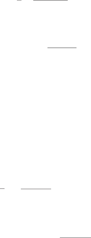
A typical variation in daily wastewater flow is shown iin Figure 20-15 a. Ideally, the fluctuation
in diurnal flow rate may be visualized as a sinusoidal wave as shown in Figure 20-15 b. From a
design and operating point of view, the ideal flow rate would be constant at the average value
HEADWORKS AND PRELIMINARY TREATMENT 20-37
shown in the figure. The reduction in the amplitude of the wave, called equalization or damping,
may be accomplished by storing the wastewater that is in excess and delivering it downstream
during the time that the flow rate is below the average flow rate.
In the idealized scenario shown in Figure 20-15 b, the shaded area above the average flow
rate is equal to the cross-hatc
hed area below the average flow rate. Each of these areas is a vol-
ume. This volume is the basis for the design of an equalization basin. It may be determined by a
volume balance analysis of the diurnal flow rate where
dS
dt
QQ
in out
(20-12)
or for a time interval of t
dS Q t Q t( )()( )()
in out
(20-13)
where dS i s the change in storage for the time increment t, and the quantities ( Q
in
)( t ) and
( Q
out
)( t ) are volumes. The analysis is made for the case where Q
out
i s a constant equal to Q
avg
.
The diurnal variation is integrated numerically and the maximum value of dS i s the required
storage.
Equalization Design Practice
The principal factors that must be considered in the design of equalization basins are: (1) location
and configuration, (2) volume, (3) basin geometry, (4) mixing and air requirements, (5) appurte-
nances, and (6) pumping facilities. These are discussed in the following paragraphs.
Location and Configuration. The basins are normally loc
ated near the head end of the
treatment works, preferably downstream of pretreatment facilities such as bar screens and grit
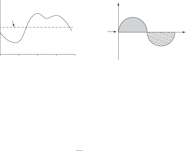
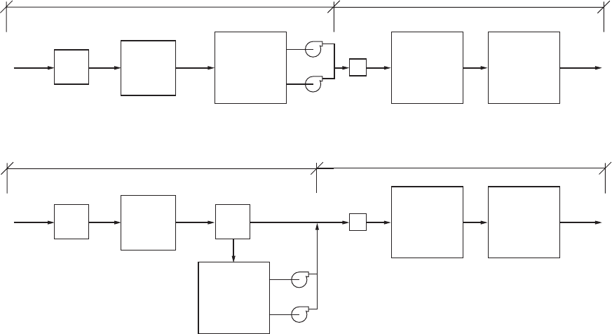
chambers. Two typical WWTP configurations are in-line equalization and off-line equalization
( Figure 20-16 ). Considerable damping of constituent mass loadings, as well as flow rate, may be
achieved with in-line equ
alization.
0600
Average
daily flow
Average
Time, h
1200
Time of day(a)(b)
Wastewater flow
Flow rate
1800 MM
FIGURE 20-15
( a) Typical and (b) highly idealized hypothetical flow patterns.
20-38 WATER AND WASTEWATER ENGINEERING
The off-line arrangem ent is typically used to attenuate wet weather flow. In this arrange-
ment, only the flow above some predetermined flow rate is diverted to the equalization basin.
This dampens the flow rate but is not effective in dam ping the diurnal variation in constituent
concentration.
Volume. As noted above, the required volume is estimated from di
urnal flow data by perform-
ing a volume balance to determine the maximum storage volume required. In practice the volume
will be larger than the theoretical value to account for the following:
1 . Operation of aeration and mixing equipment will not permit complete dewatering of an
in-line basin.
2. If recycle streams are brought to the mixing basin, this volume must be acc
ommodated.
3. Contingency for variations beyond the diurnal flow pattern.
Additional volume is provided for these contingencies. The contingency multipliers range from
1.1 to 1.25 times the theoretical estimate.
E xample 20-6 illustrates the estimation of the volume required for in-line equalization using
the mass balance techniq
ue and the concurrent damping of the BOD
5
load.
(a)
(b)
Influent
Screen
Influent
Screen
Grit
removal
Grit
removal
Equalization
basin
Equalization
basin
Primary
treatment
Secondary
treatment
Effluent
Primary
treatment
Secondary
treatment
Effluent
Flow rate is relatively constantFlow rate varies
Flow rate is relatively constantFlow rate varie
s
Overflow
structure
Flow
meter
Flow
meter
Controlled-flow
pumping station
Controlled-flow
pumping station
FIGURE 20-16
T ypical wastewater-treatment plant flow diagram incorporating flow equalization: (a) in-line equalization and (b) off-line equalization.
Flow equalization can be applied after grit removal, after primary sedimentation, and after secondary treatment where advanced treatment
is used.
( Source: Metcalf & Eddy, 2003.)

HEADWORKS AND PRELIMINARY TREATMENT 20-39
Example 20-6. Determine the equalization basin volume required for the following cyclic flow
pattern. Provide a 25% excess capacity for equipment, unexpected flow variations, and solids ac-
cumulation. Evaluate the impact of equalization on the mass loading of BOD
5
.
Time, h Flow, m
3
/s BOD
5
, mg/L Time, h Flow, m
3
/s BOD
5
, mg/L
0000 0.0481 110 1200 0.0718 160
0100 0.0359811300 0.0744 150
0200 0.0226 53 1400 0.0750 140
0300 0.0187 35 1500 0.0781 135
0400 0.0187 32 1600 0.0806 130
0500 0.0198 40 1700 0.0843 120
0600 0.0226 66 1800 0.0854125
0700 0.0359 92 1900 0.0806 150
0800 0.0509 125 2000 0.0781 200
0900 0.0631 140 2100 0.0670 215
1000 0.0670 150 2200 0.0583 170
1100 0.0682 155 2300 0.0526 130
Solution. D e sign of the equalization basin volume.
a . Because of the repetitive and tabular nature of the calculations, a spreadsheet is ideal for
this problem. The spreadsheet solution is easy to verify if the calculations are set up with
judicious selection of the initial value. If the initial value of the first flow rate is greater
than the average after the sequence of nighttime low flows
, then the last row of the com-
putation should result in a storage value of zero for a perfect sinusoidal flow pattern.
b. The first step is to calculate the average flow. In this case it is 0.05657 m
3
/ s. Next, the
flows are arranged in order beginning with the time and flow that first exceeds the aver-
age. In this case it is at 0900 h with a flow of 0.0631 m
3
/s. The tabular arrangement is
shown in Table 20-12 . An explanation of the calculations for each column is given in the
following steps.
c. In the third column, the flows are converted to volumes using the time interval between
flow measurements:
()()()0063113 600 227 16
33
.,.m /s h s/h m
V
d. The average volume that leaves the equalization basin is calculated in the fourth column.
It is the average flow rate computed on an hourly basis.
()()()00565713 600 203 655
33
.,.m /s h s/h m
V
e. The fifth column is the difference between the inflow volume and the outflow volume.
dS
in out
mm227 16 203 655 23 505
33
...
V
V
20-40 WATER AND WASTEWATER ENGINEERING
f. The required storage is computed in the sixth column. It is the cumulative sum of the
difference between the inflow and outflow. For the second time interval, it is
Storage mm m dS 37 55 23516106
33 3
...
Note that the last value for the cumulative storage is 0.12 m
3
. It is not zero because of
round-off truncation in the c omputations. At this point the equalization basin is empty
and ready to begin the next day’s cycle.
g. The required volume for the equalization basin is the maximum cumulative storage. It is
the shaded value. With the requirement for 25% exc
ess, the volume would then be
Storage m or()()863 74 1 25 1 079 68 1 080
3
..,.,m
3
Evaluation of the impact on BOD
5
loading .
TABLE 20-12
Spreadsheet Calculations for Example 20-6
Time Flow, m
3
/s Vol
in
, m
3
Vol
out
, m
3
dS, m
3
dS, m
3
BOD
5
, mg/L M
BOD-in
, kg
S, mg/L
M
BOD-out
, kg
0900 0.0631 227.16 203.65 23.5123.51 140 31.80 140.00 28.51
1000 0.067 241.2 203.65 37.55 61.06 150 36.18 149.11 30.37
1100 0.0682 245.52203.65 41.87 102.93 155 38.06 153.8331.33
1200 0.0718 258.48 203.6554.83 157.76 160 41.36158.24 32.23
1300 0.0744 267.84 203.65 64.19 221.95 150 40.18 153.06 31.17
1400 0.075 270 203.65 66.35 288.3
140 37.80 145.89 29.71
1500 0.0781 281.16 203.65 77.51 365.81 135 37.96 140.51 28.62
1600 0.0806 290.16 203.65 86.51452.32130 37.72 135.86 27.67
1700 0.0843303.48 203.65 99.83 552.15 120 36.42 129.49 26.37
1800 0.0854 307.44 203.65 103.79 655.94 125 38.43 127.89 26.04
1900 0.0806 290.16 203.65 86.51 742.45 15043.52134.67 27.43
2000 0.0781 281.16 203.65 77.
51 819.96 200 56.23 152.61 31.08
2100 0.067 241.2 203.65 37.55 857.5121551.86 166.79 33.97
2200 0.0583 209.88 203.65 6.23 863.74 170 35.68 167.42 34.10
2300 0.0526 189.36203.65 14.29 849.45 130 24.62 160.69 32.73
0000 0.0481 173.16 203.65 30.49 818.96 110 19.05 152.11 30.98
0100 0.0359 129.24 203.65 74.41 744.55 81 10.47 142.42 29.00
0200 0.0226 81.36203.65 122.29 622.26 53 4.3
1133.61 27.21
0300 0.0187 67.32203.65 136.33 485.9335 2.36123.98 25.25
0400 0.0187 67.32203.65 136.33 349.6 32 2.15 112.79 22.97
0500 0.0198 71.28 203.65 132.37 217.23 40 2.85 100.46 20.46
0600 0.0226 81.36203.65 122.29 94.94 66 5.37 91.07 18.55
0700 0.0359 129.24 203.65 74.41 20.53 92 11.89 91.61 18.66
0800 0.0509 183.24 203.65 20.41 0.12 125 22.91 121.64 24.77