Water and Wastewater Engineering
Подождите немного. Документ загружается.

21-8 WATER AND WASTEWATER ENGINEERING
Weir loading rates have little effect on the performance of primary settling tanks with
wall depths greater than 3.7 m (Metcalf & Eddy, 2003, WEF, 1998). In practice weir load-
ing rates seldom ex ceed 120 m
3
/ d · m of weir length in plants with average design flow rates
less than 3,800 m
3
/ d or 190 m
3
/ d · m in plants treating more than 3,800 m
3
/ d (WEF, 1998).
However, Metcalf & Eddy (2003) reported loading rates ranging from 125 to 500 m
3
/ d · m
with a typical value of 250 m
3
/ d · m.
Sludge Hoppers. Because the raw sludge is very sticky, it tends to accumulate on the sludge
hopper sides, in corners, and arch over the sludge draw-off piping. To minimize these effec ts,
the sludge hopper side walls should have a minimum side wall slope of 1.7 verti
cal : 1 horizontal
(60 from horizontal), and the bottom dimension s hould not exceed 0.6 m. Extra depth sludge
hoppers for sludge thickening are not acceptable (GLUMRB, 2004).
Geotechnical Considerations. The foundation of all tanks in water and wastewater treatment
must be addressed. The location of the wastewater treatment plant at a topographically low
elevation next to a river to facilitate gravity collection and wastewater d
isposal increases the
importance of geotechnical considerations. This is because the soils in these locations are often
of poor stability, and are typically saturated.
Traditional geotechnical consideration of foundation settlement is addressed in depth in
standard
texts. It will not be discussed here. The other critical issue in the design of tanks is the
potential for flotation.
The following definitions provide a basis for analysis of the problem:
• Intergranular pressure ( p
ig
): pressure that is transmitted from grain to grain of the solid
constituents of the soil.
• Porewater pressure ( p
w
): pressure that is transmitted through the water that fills the voids
of the soil.
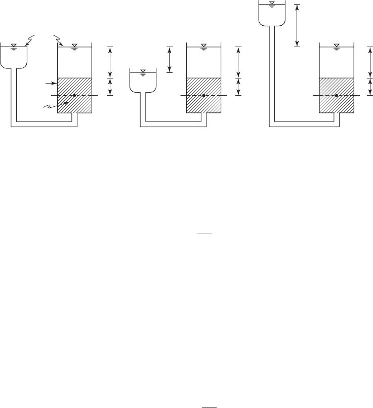
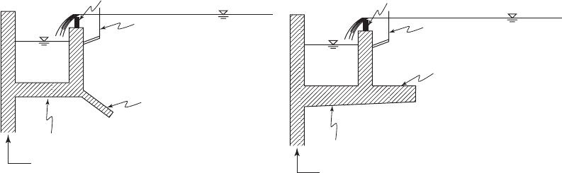
Figure 21-4 shows a laboratory setup that illustrates the problem. It consists of a container on
the right-hand side that is partly filled with granular material and completely filled with water.
A flexible tube is connected to the bottom of the container, and a reservoir of water is
on the
the left-hand side. In Figure 21-4 a the water level in the reservoir is at the same elevation as the
water level in the container so that no flow takes place. The soil is saturated. On a plane denoted
by a b at a depth H
L
z below the top of the container, the vertical pressure is
pH z
Lw
()()()()
sat
(21-3)
where p total pressure, kPa
p
ig
p
w
w
unit weight of water, kg/m
3
sat
unit weight of saturated soil, kg/m
3
and
pHz
wL w
()()
(21-4)
pz z
ig
()
sat w
(21-5)
where # submerged unit weight, kg/m
3
.
PRIMARY TREATMENT 21-9
If the hydraulic gradient is such that downward flow exists, as shown in F igu re 21-4 b, then
at H
L
z the total pressure is
pz
h
H
z
s
w
⎛
⎝
⎜
⎞
⎠
⎟
()( )
(21-6)
where h difference in elevation between the top of the reservoir and the top of the water
in the container, m
H
s
height of the soil layer in the container, m
h / H
s
hydraulic gradient, dimensionless
At the bottom of the container, the pore water pressure is
pHH h
wLs w
()()
(21-7)
If the hydraulic gradient is such that upward flow exists, as shown in Figure 21-4 c, then at
H
L
z the total pressure is
pz
h
H
z
s
w
⎛
⎝
⎜
⎞
⎠
⎟
()( )
(21-8)
When ( h / H
s
)( z )(
w
) z # , the soil cannot support any weight. This is commonly referred to
as “quicksand.”
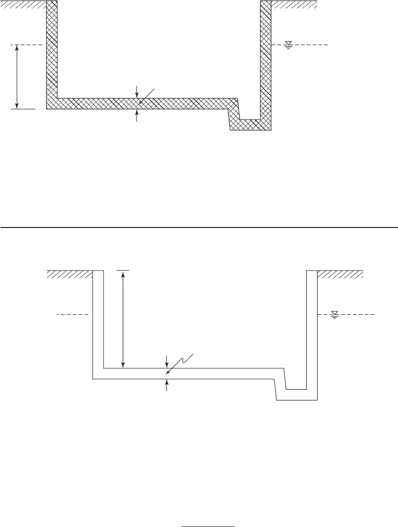
Now consider the case illustrated in Figure 21-5 where a tank has been dewatered for main-
tenance. At the bottom of the inside of the tank z # 0 and p
w
T
w
. If the product of the
thickness of the tank and the unit weight of the tank material is less than the product of the depth
of the groundwater and the unit weight of water, that is, ( a )(
tank
) ( T )(
w
), the tank will float!
Conceptually, one may visualize this as buoyancy of the tank from the displaced mass of water.
The friction on the walls of the tank and the mass of the walls are ignored in this simple analysis.
The design of tanks must then consider the very likely possibility that the tank will be
emptied at a time when the groundwater table is high. Several alternative
s are available. The
FIGURE 21-4
E xperimental set up to demonstrate pressure relationships under different groundwater scenarios.
Water
Soil
(a)(b)(c)
␥
w
ab
␥
sat
␥
w
⌬h
ab ab
H
L
Z
⌬h
H
L
Z
H
L
Z
21-10 WATER AND WASTEWATER ENGINEERING
alternatives include anchors being driven into the soil below the tank, thickening the bottom of
the tank (i.e., the dimension “ a ”) to increase the mass, providing mud valves in the bottom of the
tank, or a combination of these measures.
E xample 21-1 illustrates the geotechnical analysis of a settling tank.
Example 21-1. For the sketch shown below, determine the elevation of the groundwater table
that will cause the tank to “float.” Assu
me that the density of the concrete is 2,400 kg/m
3
.
0.30 m
GWT
Elev. 280.00
4.3 m
Solution:
a . The load of the tank on the soil is
()( ) ( )( )a
concrete
m kg/m kg0 3 0 2 400 720
3
., //m
2
b. Set the pore water pressure equal to the load and solve for h a ssuming
w
1,000 kg/m
3
.
()()
h
h
w
720
720
1 000
0
2
2
3
kg/m
kg/m
kg/m,
..72 m
⌬T
a
GWT
FIGURE 21-5
E mpty tank with high ground water table (GWT). concrete thickness a.

PRIMARY TREATMENT 21-11
c. The elevation of the bottom of the tank is
Elevation of bottom mmm280 00 4 3 0 3 27...5540. m
d. Elevation of groundwater table that is incipient to flotation:
Elev mm m.. . .275 40 0 72 276 12
Comment. Because of soil friction and the mass of the tank walls, the groundwater table will
have to be somewhat higher than shown by this calculation to cause flotation of the tank.
Circular Sedimentation Basin Design
Because center feed basins are the most commonly used systems, only they are discussed here.
The specific elements to be considered are the diameter, depth, flow balancing, inlet configura-
tion, sludge removal, and scum removal.
Diameter. Overflow rate is the controlling variable in d
etermining both the area and the diam-
eter of a circular clarifier. Although tanks up to 100 m in diameter have been built, generally they
are limited to about 50 m because of the effects of wind (Tekippe, 2006). Metcalf & Eddy (2003)
reported ranges from 3 to 60 m with typical values of 12 to 45 m.
Depth. Depths are measured as side water depth.
With a sloped floor, the depth at the center of
the tank will be deeper. Most floors have a constant floor slope of 1 on 12 (vertical:horizontal).
The origin of this particular slope is uncertain, but it has received widespread use for decades
(Tekippe, 2006).
The tanks must be deep enough to accommodate mechanical equipment for sludge removal,
store settled
solids, avoid scour, and avoid carryover of solids in the effluent. Excessive depth is to
be avoided to prevent anaerobic conditions. Shallower tanks may be acceptable with continuous
sludge removal.
Theoretically, removal efficiency should increase with depth because the opportunity
for
particle contact and flocculation increase with depth. In practice, it has been found that depth and
overflow rate are intimately related. To achieve the highest efficiency, deeper tanks with lower
overflow rates are required (Tekippe, 2006). Reported depths have ranged from 3 to 5 m with
a typical value of 4.3 m (Metcalf & Eddy, 2003; WEF, 1998). Current trends favor the use of
deeper tanks (Wahlberg, 2006).
Common practice is to provide a freeboard of 0.5 to 0.7 m.
Splitter Box. When multiple units are in service, the flow must be split so that both the hydraulic
load and the solids load are in proportion to the design limits of the tank. Upflow distribution
structures ( splitting boxes ) with fixed weirs can be used to provid
e identical flow to identical
multiple units ( Figure 21-6 ). Weir lengths are adjusted in proportion to the surface area if the units
have different surface areas. When the settling tanks have different side water depths, the weir
lengths are adjusted so that they are proportional to the volume of the tanks. When both the
surface area and depth of the tanks differ, the weir length is adjusted in proportion to the volu
me
of the tanks. To minimize turbulent conditions, the upflow velocity into the flow splitting box
should be less than 0.3 m/s at peak flow. The top of the discharge should be sufficiently below

21-12 WATER AND WASTEWATER ENGINEERING
the weir to dissipate turbulence at the weir. A depth of two to three times the diameter (or height)
of the inlet pipe should be sufficient for velocities less than 1 m/s. Deeper boxes are required for
higher velocities (Wahlberg, 2006). To isolate a tank for service, a sluice gate is placed on the
outlet of the splitter box.
One type of weir that may be used is a sharp-crested re
ctangular weir. Under free flow condi-
tions, the head over the weir may be calculated as
h
Q
CL
sc
w
2 3/
()()
⎡
⎣
⎢
⎤
⎦
⎥
(21-9)
where h
sc
head over the weir crest, m
Q flow rate, m
3
/ s
C
w
discharge coefficient, dimensionless
L length of weir, m
The commonly used value for C
w
i s 1.82. Typically, end contractions (projections from sides of
the channel) are present. To account for these, a modified form of Equation 21-9 is used:
h
Q
CL h
sc
wsc
2 3
02
/
()( ).
⎡
⎣
⎢
⎤
⎦
⎥
(21-10)
E xample 21-2 illustrates the design of a splitter box.
Example 21-2. The Camptown wastewater treatment plant is being designed to treat a flow
rate of 56,800 m
3
/ d. Eight identical circular primary tanks will be used. Each pair will be served
by one splitter box. Using a sharp-crested rectangular weir, design a splitter box for two identical
circular clarifiers. Assume a peaking factor of 2.3 for the plant.
2.5 m
1.4 m
2.5 m
(
a
)
(
b
)
2.1 m
Effl
u
ent
Infl
u
e
nt
1,0
5
0
mm
d
ia
m
eter
Effl
u
ent
0.6 m
Weir plate
weir length
FIGURE 21-6
Splitter box. Dimensions are those found in Example 21-2. They are not standard.

PRIMARY TREATMENT 21-13
Solution:
a . Note that the clarifiers are identical, so one-eighth of the flow must go to each. Convert
the flow rate to appropriate units.
Q
Q
56 800
8
7 100
71
3
3
,
,
,
m /d
tanks
m /d tank
000
86 400
0 082
3
3
m /d tank
s/d
m /s per ta
,
. nnk
b. For a first trial, assume a head over the weir crest of 100 mm and use Equation 21-10 to
determine the length of the weir.
2 3
3
0 082
182 02 010
/
m /s
m
.
...( )[ ( )( )]L
⎡
⎣
⎢
⎤
⎦
⎥
0010. m
Solving for L,
L 1425 02 010 1445 14.....()( ) or m
c. Select an inlet pipe diameter to achieve a velocity of 0.3 m/s at peak flow. At peak flow
with one tank out of service, the flow per tank for the remaining seven is estimated as
Q
peak
m /d
s/d tank
()( )
()(
2 3 56 800
86 400 7
3
.,
,
ss
m /s
Area of pipe
m /s
m/
)
= 0 216
0 216
0 3
3
3
.
.
.
ss
m= 0 720
2
.
The diameter of the pipe is found from the area:
()D
2
2
4
0 720 . m
and D .957 m.
Select a standard pipe size 1,050 mm.
d. The depth of the box below the weir is two times the diameter of the pipe:
Depth mm()( )2105 21..
e. Allowing for free discharge over the weir, select a plan area of 2.5 m 2.5 m. The final
splitter box with 0.6 m freeboard above the maximum head on the weir is s ketched in
Figure 21-6 .
21-14 WATER AND WASTEWATER ENGINEERING
Comments:
1 . Other weirs, such as a v-notch, may also be used.
2. If one tank is out of service when the peak flow occurs, the head over the weir will be
higher.
Hints from the Field. Operators and experienced engineers have provided the following
insights on the design of splitter boxes:
• The splitter box has the potential to be the crucial element in limiting the flexibility of
operation of the plant. If the splitter box res
tricts the flow rate, the operator cannot adjust
hydraulic loads during peak flows or when tanks are out of service.
• I solation of a clarifier for service causes the ou tlet chamber to fill. Because it is stagnant,
this may become a s ource of odors. For small installations, a simple cover m
ay serve to
mitigate the problem.
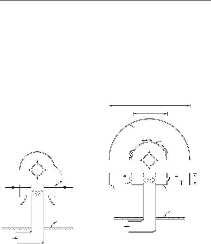
Inlet Configuration. The typical center feed tank has a vertical inlet pipe with ports that
transmit the flow from the feed pipe to the feed well ( Figure 21-7 ). The feedwell (also called a
flocculation center well ) s hould be equipped with an energy dissipating device to break up the
jetting velocity into the inlet baffle area ( Figure 21-8 ).
(a) Plan
Feed well
(b) Profile
Influent
Tank Floor
FIGURE 21-7
Standard center inlet.
(a) Plan
(b) Profile
Influent
Tank Floor
Feedwell
EDI
EDI
Feed well
Feed well dia. 14m
EDI dia. 4m
EDI
0.9–1 m
0.75 m
FIGURE 21-8
Center Feed with energy dissipating inlet (EDI). Approximate
dimensions are for a 55 m diameter primary tank with a 4.6 m
side water depth.
PRIMARY TREATMENT 21-15
The feedwell can promote flocculation. Based on experimental observations, a detention
time of about 20 minutes achieves over 90 percent of the obtainable flocculation. This has led to
a rule of thumb that the flocculation center well should be sized to obtain 20 minutes of residence
time at average dry weather flow. An additional 50 percent allowance is rec
ommended when
return activated sludge is added to the clarifier (Tekippe, 2006). It has been observed that, if the
flocculation center well is too large, short circuiting may result.
The depth of the projection of the feedwell above the liquid level, and into the wastewater, are
also important design criteria. The top elevation of the feedwell is generally designed to extend
above the liquid level at peak ho
ur flow with one unit out of service. Typically, four ports are cut
in the top portion of the feedwell to allow scum to move out of the feedwell into the tank proper.
The projection of the feedwell downward into the tank may range from 30 to 75 percent of
the tank depth. Some manufacturers recommend that submergence be 25 to 50 percent of the side
water depth (Tekippe, 2006). The selec
tion of the depth requires a balance of three components:
(1) the need to prevent jetting from the inlet pipe ports, (2) the need to prevent energy dissipating
device outflows from passing under the feedwell, and (3) the need to prevent a high horizontal
discharge velocity that will scour settled sludge.
Energy dissipating inlets (EDIs) are used to distribute flow within the feed
well ( Figure 21-8 ).
These also mix the wastewater and provide a means of increasing flocculation. The diameter of
the EDI assembly is often set at 10 to 13 percent of the tank diameter. Alternatively, it is designed
to provide a detention time of 8 to 10 s. If the EDI assembly or ring is too large, it reduces the
volume of the flocculation zone and increases
downward velocities.
Unfortunately, the wide range of rec ommendations for feedwell and EDI dimensions
allows almost any configuration without any assurance of a successful design. Computational
fluid dynamic (CFD) modeling offers some possibility of optimizing the design. In the
abs
ence of CFD modeling, it appears that increas ing the depth of the tank, using a low over-
flow rate and baffles (discussed later in this section) in conjunction with EDIs and a 20 s
detention time in the feedwell provides the best opportunity for maximizing the primary
clarifier efficiency.
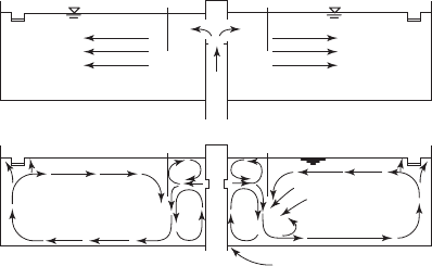
Baffles. Currents in an ideal clarifier and in an unbaffled clarifier are s
hown schematically in
Figure 21-9 . Two important conclusions may be drawn from the model: (1) there is a circulation
pattern rather than the idealized radial flow, and (2) there is a smaller vertical circulation pattern
below the feedwell. The circulation pattern at the weir results in carryover of solids. This is
e specially evident with inboar
d weirs. The vertical circulation pattern tends to carry sludge that
(b)
(a)
Stagnant zone
Blanket
filtration
zone
Compacted sludge
FIGURE 21-9
( a ) Ideal and ( b ) typical velocity pattern in center feed
circular clarifier.
21-16 WATER AND WASTEWATER ENGINEERING
has been scraped toward the hopper near the center of the tank back into wastewater. In addition
to these effects , velocity measurements in full scale, shallow tanks with deep feedwells show
high velocities across the sludge (Albertson and Alfonso, 1995).
To rectify these problems, three design adjustments are offered (Alberts
on and Alfonso,
1995; Stukenberg et al., 1983). The first is to use a wall-mounted effluent weir with a baffle
as shown in Figure 21-10 . The second is to provide a horizontal baffle beneath the feedwell as
shown in Figure 21-11 . The third is to reduce the depth of the feedwell.
Weir Configuration. Outlets for most circular center-feed clarifiers consist of a single perim
eter
v-notch weir that overflows into an effluent trough (Figures 21-1a and 21-10). Alternatives include
cantilevered or suspended double weir troughs, and submerged-orifices. The preferred design is
to mount the perimeter weir on a trough on the inside of the tank ( Figures 21-1 a and 21-10). This
arrangement helps deflect some of the “wall effect”
solids updraft inward near the surface and
reduces the loss of suspended solids over the weir (Tekippe, 2006).
Algae growth is a problem with many clarifiers with open troughs. This is both a mainte-
nance issue and a water quality issue as the algae break free and contribute to the effluent sus-
pended solids load. Strategies that have been foun
d to be effective in minimizing algae growth
include installing trough covers, mounting algae brushes on the rotating mechanism, feeding
chlorine solution, and hydraulic spray washing.
Sludge Scraper. The straight, multiblade scraper is the most widely used mechanism for primary
tanks. Ty
pically, they are manufactured with two arms in 1.5 m increments from 9 to 50 m. In
the United States, the drive mechanism commonly provides torque applied at the center column.
In Europe, it is common to have a drive located at the tank wall. The scraper plows furrows of
sludge progress
ively toward a centrally located hopper. They are designed to rotate at a tip speed
of approximately 3 m/min (Tekippe, 2006).
Sludge transport, treatment and disposal are discussed in Chapter 27.
Scum Removal. The most common system uses a rotating skimmer arm and wiper attached
to the scraper me
chanism. It travels around the outer edge of the tank next to the scum baffle
Baffle
Launder
Tank wall
Scum baffle
Weir
Launder
Baffle
Scum baffle
Weir
Tank wall
FIGURE 21-10
Examples of baffle arrangements at launder .
PRIMARY TREATMENT 21-17
( Figure 21-10 ). The scum baffle should project 200 to 300 mm below the water surface (U.S.
EPA, 1974). The skimmer arm moves the floatable m aterial onto a beach, or egress ramp,
connected to a scum removal box ( Figure 21-12 ). The skimmer blade is most effective if it
is attached tangentially to the feedwell baffle, rather than perpendicular to it. The pitch angle
helps to move the floating
material to the scum baffle. Once during each rotation, the scum is
pushed up on the beach and into the discharge trough. The box is flushed to the scum piping
sys tem with wastewater from the tank.
S cum transport, treatment, and disposal are discussed in Chapter 27.
E xample 21-3 illustrates the de
sign of a circular sedimentation basin.
Example 21-3. Design a circular primary clarifier for the Camptown WWTP ( Example 21-2 ).
Assume an overflow rate of 40 m
3
/ d · m
2
, a side water depth of 4.3 m, and a sludge hopper vol-
ume of approximately 1 m
3
. To complete the design provide the following:
D i a meter of tank
Diameter and depth of feedwell
Diameter and depth of EDI
D i mensions of sludge hopper
Check of velocity across sludge zone
Calculation of the weir loading rate
Influent
Feed well
Circular
baffle
FIGURE 21-11
Circular baffle at inlet to reduce cascade effect .
Scum beach
Discharge trough
Discharge pipe
Scum baffle
FIGURE 21-12
S cum “beach” for circular clarifier.