Water and Wastewater Engineering
Подождите немного. Документ загружается.


21-18 WATER AND WASTEWATER ENGINEERING
Solution:
a . From Example 21-2 , the flow rate for the clarifier is 7,100 m
3
/ d . The diameter of the
tank is calculated as follows:
Surfacearea
m /d
m /dm
Q
v
0
3
3 2
7 100
40
177
,
..
.
.
5
4
177 5
177 5 4
2
2
2
2
m
m
m
tank
tank
()
)( )
D
D
⎛
⎝
⎜
⎞
⎠
⎟
15 03 15.or m
This is a standard diameter for sludge removal equipment.
b. Assuming a detention time of 20 min in the feedwell, and a depth equal to 50% of the
tank depth, the feedwell dimensions are estimated as follows:
()7 100
20
1 440
98 6
3
,.m /d
min
min/d,
⎛
⎝
⎜
⎞
⎠
⎟
mm
Depth of feedwell mm
Su
3
0 5043 215()( ).. .
rrfaceareaoffeedwell
m
m
98 6
215
45 86
3
.
.
.
m
m
feedwell
feedwell
2
2
2
4
45 86
45 86
()
(
D
D
.
.
m
m
2
4
764
)( )
⎛
⎝
⎜
⎞
⎠
⎟
.
V
This is slightly more than half the diameter of the tank and appears to be quite large.
c. Check the flow velocity.
The area of the cylinder through which the wastewater must flow is
ADh
cylinder
mm m
()( )764 43 215516... .mm
2
Note that h side water depth minus the depth of the feedwell.
The velocity through this area is
v
7 100
51 6 86 400
0 002
3
2
,
.,
.
m /d
m s/d
m/s
()( )
This is substantially below the criteria of 0.020 m/s. Therefore, increase the depth of the
feedwell to reduce the diameter.

PRIMARY TREATMENT 21-19
d. After another iteration, the feedwell dimensions selected are 6.2 m diameter and 3.2 m
depth. The resulting velocity is estimated at 0.004 m/s.
e. Using 10 s detention and a depth of one-half that of the feedwell (1.6 m), the EDI
diameter is estimated as
()7 100
10
86 400
0 822
33
,
,
.m /d
s
s/d
m
⎛
⎝
⎜
⎞
⎠
⎟
SSurfaceareaofEDI
m
m
m
0 822
16
0 51
3
2
.
.
.
(()
()()
D
D
EDI
EDI
m
m
2
2
2
4
0 51
0 514
0
.
.
⎛
⎝
⎜
⎞
⎠
⎟
.. .809 0 8or m
V
f. The bottom of the sludge hopper should not exceed 0.6 m in width, and the angle of
the side wall must be greater than 60 . The shape of the hopper is the frustum of a right
pyramid. The volume is given by:
h
WW WW
3
12
⎛
⎝
⎞
⎠
{[()()]}
top bottom top bottom
/
V
The volume required is 1 m
3
. Assume W
bottom
0.6 m. There are two unknowns: the
height, h, and W
top
. Using the Solver * tool in a spreadsheet with W
bottom
0.6 m, the
dimensions were found to be:
Bottom 0.6 m
Top 1.19 or 1.2 m
Height 1.139 m or 1.2 m
Angle of side wall 75
g. Place baffles as shown in Figure 21-11 .
h. The weir loading rate is the flow rate divided by the perimeter of the tank. At the design
flow rate:
Weir loading
m /d
m
or
7 100
15
15066 15
3
,
.
()
00
3
m /dm
This is within the customary range of weir loading rates.
* Solver is a “tool” in Excel
®
. Other spreadsheets may have a different name for this program.
21-20 WATER AND WASTEWATER ENGINEERING
Comments:
1 . These dimensions are only preliminary estimates. The dimensions must conform to the
manufacturer’s standard dimensions to minimize special-order costs.
2. The placement of flocculator paddles in the feedwell may allow s
ome reduction in volume.
It will increase the efficiency of flocculation.
Rectangular Tanks
Dimensions. The length of the tank is seldom greater than 110 m and is typically in the range
of 30 to 60 m. In very small tanks, a minimum flow length of 3 m is recommended. Because of
wind currents, the difficulty in moving sludge to the hoppers, as well as the mechanical stress on
the chain and flight
system, long lengths are limited to very large plants.
Widths range from 3 to 24 m. The width increments are determined by the manufactured
widths of the chain-in-flight sludge scrapers. If widths greater than 6 m are required, multiple
bays in one tank may be used. This will permit width
s up to 24 m (Metcalf & Eddy, 2003).
The floor slope is typically 1 percent toward the sludge hoppers. Side water depth is gener-
ally measured at the effluent end wall. The range of depths is from 2 to 5 m with a typical value
of 4.3 m (Metcalf & Eddy, 2003). It is good practice to provide a depth of 4 m below the effluent
weirs (Pettit, 2006). Co
mmon practice is to provide a freeboard of 0.5 to 0.7 m.
Flow Distribution. Because rectangular tanks are typically constructed side-by-side to take
ad vantage of common walls, the distribution of wastewater is by a s ingle channel that runs
perpendicular to the flow through the tanks. The channel is covered with re
movable grates that
allow access for cleaning. The design velocity of the c hannel should be a minimum of 0.3 m/s to
prevent deposition of organic matter and a minimum of 0.75 m/s to prevent deposition of mineral
matter at 50 percent of the design flow (Metcalf & Eddy, 1991; WEF, 1998). The channel design
must provide an allowance for scum
and a method for transferring scum to the primary tank. The
scum from the primary tank and the channels is collected together for disposal.
One of three alternatives is generally used to provide equal flow distribution: inlet weirs,
submerged orifices, or inlet gates. Weir inlets that discharge directly into the tank surface
should
be avoided to minimize odors and to prevent undue turbulence at the head end of the tank.
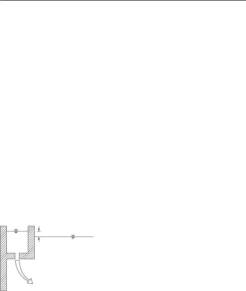
S ubmerged orifices ( Figure 21-13 ) are acceptable. They may cause an undesirable backwater
curve during peak flows. Storm inlet gates may have to be provided for this possibility. When flows
FIGURE 21-13
Distribution channel with submerged orifice.
⌬h
Settling tan
k
Distribution
channel
PRIMARY TREATMENT 21-21
are too low, the orifice may not be sufficiently restrictive to balance the flows. In this instance, the
operator must recognize the need to take one or more units off-line. Orifices are plugged when a
unit is taken out of service for maintenance. This will, of course, unbalance the flows.
S ubmerged gates seem to provide the most flexibility. The po
sition of the gates can be
adjusted for any extended flow condition. If gates are used, it is essential that automated
actuators be provided. Each gate must have an associated accurate flow meter with a feedback
signal to modulate the valve position (Tekippe, 2006; Wahlberg, 2006).
The design of the distribution channel is a complex
open channel flow problem. Benefield
et al. (1984) provide a detailed calculation procedure and a Fortran program for the design.
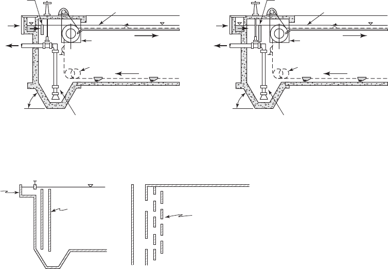
Inlet Configuration. There is no consensus on the design of the inlet. Recommendations
include placing the inlet port lower in the tank, limiting inlet port velocities to a range of 0.075
to 0.150 m/s, using inlet diffusers, placing an inlet baffle ( target or finger baffle ) in the flow path
( Figure 21-14 ), and
placing slotted or perforated baffles across the full width of the settling tank
( Figure 21-15 ). There is agreement on one point: in no case should the design permit a waterfall
into the tank (Pettit, 2006).
The typical inlet configuration includes multiple ports placed and sized to uniformly distribute
the flow over the width of the clarifier. For a 6 m wi
de tank, there are typically three or four inlet
ports. Maximum horizontal spacing is less than 3 m and typically about 2 m.
Recess for
drive chain
Flow
Take up
Influent
channel
Sludge
Water level
Sludge
hopper
60º (min)
Travel
Finger baffle
Recess for
drive chain
Flow
Take up
Influent
channel
Sludge
Water level
Sludge
hopper
60º (min)
Travel
Target baffle
(a)
(b)
FIGURE 21-14
E xamples of ( a ) target and ( b ) finger baffles.
Slotted baffle
Slotted baffle
(b) Plan(a) Profile
Influent
channel
Influent channel
FIGURE 21-15
Slotted baffles in a rectangular primary tank.
21-22 WATER AND WASTEWATER ENGINEERING
An orifice inlet that exits the bottom of the inlet channel allows for a discharge pipe exit that
is below the liquid surface. The range of location for the discharge is from a depth of approxi-
mately 2 m to midtank depth (Petit, 2006).
The function of target or finger baffles is to dissipate the jetting energy of the influent. The
target baffle is solid. The finger baffle is perforated. Baffles are typically placed 0.6 to 0.9 m from
the inlet and submerged 0.5 to 0.6 m, depending on the tank depth. The top of the baffle must be
far enough below the wastewater surface to allow scum to pass over the top (WEF, 1998).
Two offset, slotted baffles with the slots offs et have proven effective in distributing flow
evenly across the tank. The baffles should extend to at least one-half the tank depth (U.S. EPA,
1974). Kawamura (1981) recommends the ins
tallation of three perforated baffles across the full
width of the tank. Individual slots should be not less than 50 mm wide (or in diameter, if perfo-
rations are used) to minim ize plugging with rags or plastic bags. The diameter of perforations
should not be greater than 100 mm to avoid persistent jets . A porosity factor of 0.05 (5 percent
open area) is typi
cal (Krebs et al., 1992). This baffle system provides the additional advantage of
providing some flocculation.
Weir Configuration. Unwanted hydraulic patterns that are produc ed by the bottom density
current can be s trong in the region next to the end of the tank. When the flow reaches the end
wall, there is a strong upward current. This is particularly of con
cern if the sludge hoppers are
placed at the end of the tank.
Although a number of alternative arrangements of the effluent launders have been used, the
orientation does not appear to be critical (Kawamura and Lang, 1986; Pettit, 2006). What does
appear to be important is that to avoid the strong upflow when the tank current reaches the end
wall, the launder cannot be placed near the end wall. Comparable results can be obtained with
either long parallel flow launders or short parallel flow launders if they are placed away from the
end of the tank. From an economic point of view, short or transverse launders are less expensive
to build. This appears to be the most typical arrangement (WEF, 1998).
To avoid loss of solids due to end wall upflow, placement of the laund
er at a distance from
the outlet wall equal to the wastewater depth is recommended (ATV, 1988).
Sludge Removal. The two classes of sludge removal systems are the chain-and-flight and the
traveling bridge. In the United States, the chain-and-flight systems are more common. Although
the traveling bridge may be equipped with either a scraper or a suction s
ystem, the suction mech-
anism is not used in primary clarifiers. The traveling bridge is noted for its higher construction
and maintenance costs (Pettit, 2006).
With the exception that the return flights move across the surface of the tank ( Figure 21-3 ),
chain-and-flight systems are very similar to those
discussed in Chapter 10, and the reader is
referred there for more details. The flight speed ranges from 0.3 to 1.2 m/min with a typical speed
of 0.9 m/min. In general they are operated periodically rather than continuously.
Although the sludge hoppers may be placed at the influent end, effluent end, or in the middle
of the tank, they are often pla
ced at the influent end in primary settling tanks. This places the
hoppers near where the bulk of the solids settle. It also alleviates the scour that lifts the solids
up into the effluent weirs at the end wall. The disadvantage of locating the hopper at the head
end of the tank is that the flight scraper induces a volumetric flow rate at the bottom of the tank
that is countercurrent to the den
sity flow current in the fluid above the sludge blanket. This may
resuspend solids.

PRIMARY TREATMENT 21-23
A single sludge hopper with a cross-collector is preferred over multiple hoppers (Metcalf &
Eddy, 2003).
Sludge transport, treatment and disposal is discussed in Chapter 27.
Scum Removal. The typical scum removal system utilizes the return of the chain-and-flight
scraper at the surface of the tank to move the scum
toward the effluent ( Figure 21-3 ). The scum is
trapped by a scum baffle and/or, more commonly, a slotted pipe. The slotted pipe is periodically
turned to allow the scum to be carried into the slot. The scum baffle should extend 0.3 to 0.6 m
below the surface and 30 mm above the su
rface. It should be not less than 0.6 m upstream from
the outlet weir (Pettit, 2006).
S cum transport, treatment, and disposal are discussed in Chapter 27.
Primary Sedimentation Tank Design Criteria
T ypical design criteria are summarized in Table 21-1 . Some design criteria are quite rigid, while
others only provide guidance. For example, because of manufacturing constraints, the length of a
chain-and-flight collection sets a firm maximum on the length of the settling basin. Although the
maximu
m width is 6 m, multiple units may be mounted in parallel to achieve widths up to 24 m.
Parameter Range of values Typical/comment
General
Overflow rate (average flow) 30 to 50 m
3
/d · m
2
40 m
3
/d · m
2
Overflow rate (peak flow) 60 to 120 m
3
/d · m
2
100 m
3
/d · m
2
Detention time (average flow) 1.5 to 2.5 h 2.0 h
Flow velocity 0.020 to 0.025 m/s
Weir loading rate 125 to 500 m
3
/d · m 250 m
3
/d · m
Sludge hoppers 1.7 vertical to 1 horizontal Minimum; bottom width 0.6 m
Geotechnical Consider potential for flotation
when tank is empty
Circular tanks
Dimensions
Diameter 3 to 100 m 12 to 45 m
Standard 9 to 45 m In 1.5 m increments
Side water depth 3 to 5 m 4.3 m
Floor slope 1 vertical to 12 horizontal
Splitter box
Inlet velocity
0.3 m/s At peak flow
Inlet configuration
Detention time 20 minutesFeedwell
Submergence 30 to 75% of depth Size to prevent scour
EDI detention time 8 to 10 s
TABLE 21-1
Typical design criteria for primary sedimentation basins
(continued)

21-24 WATER AND WASTEWATER ENGINEERING
Parameter Range of values Typical/comment
Baffles
Effluent Below weir
Horizontal Below feedwell
Rectangular tanks
Dimensions
Length 30 to 110 m 30 to 60 m
Width 3 to 24 m 6 m max per flight
Depth 2 to 5 m 4.3 m
Floor slope 1%
Distribution channel
Velocity 0.3 to 0.75 m/s
Flow distribution Prefer orifices or gates
Inlet configuration
Ports
3 to 4 per tank at 3 m 2 m
Energy dissipation Target or finger baffle
Baffles
Distance 0.6 to 0.9 m from inlet
Submergence0.5 to 0.6 m
Porosity Individual openings 5 cm
and 10 cm
5% open area
Sources: GLUMRB, 2004; Krebs et al., 1992; Metcalf & Eddy, 2003; Pettit, 2006; Tekippe, 2006; Wahlberg et al., 1994;
Wahlberg, 2006; WEF, 1998.
TABLE 21-1 (continued)
Typical design criteria for primary sedimentation basins
A n e xample of the design of horizontal flow basin is presented in Chapter 10. Of course, the cri-
teria for primary sedimentation basins are different and these must be accounted for in the design.
Operation and Maintenance
Provisions should be made for taking tanks out of service and dewatering. This includes recogni-
tion of the following:
• Dewatering a tank may result in untoward groundwater pressure that will have to be
relieved.
• Taking one rectangular tank out of service that is paired with another tank requires provi-
sion for disengaging the drive and isolating the sludge pump so the rem
aining tank can
remain in service.
• Interior walls must be designed for hydrostatic pressure on one side only.
Clean weir plates prevent unbalanced flows. Some designers provide covers to prevent algae
growth. Alternatively, wiper blades are provided.
In circular tanks, the beach should be continuously flushed
to prevent scum from clogging
the lines.
PRIMARY TREATMENT 21-25
Hose bibs should be provided at each tank, scum trough, sump, and pumping station for
maintenance and clean up. Piping for treated wastewater may be used, provided it is separated
from potable water and is clearly marked as nonpotable.
21-5 OTHER PRIMARY TREATMENT ALTERNATIVES
Three modifications/alternatives may be used in primary treatment. Enhanced sedimentation and
plate settlers are modifications to standard sedimentation, and fine screens are used in lieu of
sedimentation. Each of these will be discussed in the following sections.
Enhanced Sedimentation
The simple act of promoting increased contact between particles at the inlet of the sedimentation
basin is a form of enhanced sedimentation. More commonly, enhanced sedimentation refers to the
addition of chemicals. This practice is called chemically enhanced primary treatment (CEPT). As
discusse
d in Chapter 6, the addition of chemicals, followed by gentle agitation results in coagula-
tion of particles. The resulting increase in particle size enhances the efficiency of sedimentation.
Increases of 40 to 80 percent in organic carbon removal and 60 to 90 percent in total suspended
solids removal can be achieved in shorter settling times than conventional
sedimentation.
CEPT is most effective if a complete treatment train, including rapid mix, coagulation, and
sedimentation, are provided. However, substantial improvements can be achieved by adding the
chemicals to aerated grit chambers or other upstream facilities for mixing, and us
ing the inlet
structures of a conventional primary settling tank to provide flocculation.
Alum (Al
2
(SO)
4
· 14H
2
O) or ferric chloride (FeCl
3
) added in conjunction with anionic poly-
mers are the chemicals most frequently used. Current practice is to use metal salt doses on the
order of 20 to 40 mg/L in combination with polymer doses of less than 1 mg/L. Metcalf & Eddy
(2003) recommends velocity gradients
for flocculation in the range 200 to 400 s
1
.
The use of metal salts also results in precipitation of phosphorus. This may be a positive step
in meeting discharge standards. It also may be detrimental to the downstream biological processes
that require phosphorus. As an alternative, anionic polymers alone in high doses (8 mg/L) are
effective coag
ulants that do not remove phosphorus (Reardon, 2006).
CEPT may be used on an intermittent basis to achieve effective primary sedimentation during
peak hydraulic events. This approach uses less chemicals and produces less sludge to handle.
Table 21-2 summarizes the advantages an
d disadvantages of CEPT.
Plate Settlers
Theoretical and design practices for inclined plate and tube settlers were discussed in Chapter 10.
For more details the reader is referred there.
Although plate settlers have not been commonly used in municipal wastewater treatment
plants in the United States, they have been used extensively in Europe. Metcalf & Eddy (2003
)
suggests an appropriate application is in conjunction with CEPT.
The common design is a countercurrent flow pattern. The influent is fed under the plates or
tubes and flow is upwards. Solids settle to the plate and slide down the surface to the bottom of
the tank.
For primary sedimentation applications, they inc
rease the settling area by a factor of 8 to 10.
This permits a smaller footprint or increases the capacity of existing overloaded tanks. They have
been reported to produce a more dilute sludge. This may increase the cost of sludge handling.

21-26 WATER AND WASTEWATER ENGINEERING
Potential problems that must be addressed are clogging from solids, algae, or grease. Fine
screening, adequate grit removal, and enclosing the tank are some of the rem edies offered for
these problems. Maintenance requirements are expected to be higher than for standard settling
tanks. Provision of independently supported units, eas
y access to the plates, and plates that can be
independently removed are recommended (Reardon, 2006).
Fine Screens
Where high removal efficiencies are not required, for example, in biological phosphorus removal
or membrane bioreactors, fine screens may be appropriate in place of sedimentation. Fine screens
with openings from 0.25 to 1.5 mm typically only achieve removal efficiencies of 5 to 45 percent
for suspended s
olids and 5 to 50 percent for BOD
5
(Metcalf & Eddy, 2003). The design practices
for fine screens are discussed in Chapter 20.
TABLE 21-2
Advantages and disadvantages of CEPT
Advantages Disadvantages
Increased removal of BOD, TSS, phosphorus,
and metals
May remove too much phosphorus, thus making the
primary effluent nutrient deficient
Increases primary tank capacity by allowing higher
overflow rate
Chemical handling facilities required
Increases abilit
y to absorb shock loads/wet weather
flows
Chemical safety issues and regulatory requirements
increase
Reduces size or increases capacity of biological
process
Sludge quantities increase
Enhances biological treatment kinetics May decreas
e biological sludge settleability
Decreases carbon to nitrogen ratio thus increasing
the fraction of nitrifying microorganisms and
enhancing ammonia removal
A dapted from Reardon, 2006.
Visit the text website at www.mhprofessional.com/wwe for supplementary materials
and a gallery of additional photos.
21-6 CHAPTER REVIEW
When you have completed studying this chapter, you should be able to do the following without
the aid of your textbook or notes:
1 . Explain why there is an optimum hydraulic detention time for a primary settling tank.
2 . Describe some of the practical aspects to be considered in setting the depth of a primary
settling tank.
3. Describe the method for establishing the limiting upper bound
of the velocity through a
primary settling tank.

PRIMARY TREATMENT 21-27
4. Discuss the proposed design philosophy for primary sedimentation practice explaining
when it does and does not make sense.
5. Sketch a flow-splitting box and describe how flow is adjusted when the clarifiers are
not identical.
6. Explain why hydraulic detention time
s greater than 1.5 hours are undesirable.
7. Draw a sketch to explain why an empty settling tank might “float.”
8. Sketch an EDI.
9. Sketch a baffle to be used at a perimeter weir on a circular settling tank.
10. Define CEPT and explain its role in improving settling tank efficiency.
W ith the aid of this text, you should be able to do the following:
11. Determine the half life of the number of particles per unit volume or the n
umber
remaining, given the collision efficiency, velocity gradient, and volume of particles
per unit volume.
12. Estimate the scour velocity for sticky organic particles given their density.
13. Given diurnal flow pattern, estimate the ratio of the peak four-hour flow to the average flow.
14. Estimate the actual overflow rate and/or detention time for a given s
ettling tank design
and a diurnal flow pattern.
15. Determine whether or not a tank will “float” given the tank dimensions and the eleva-
tions of the tank bottom and the groundwater table.
16. Estimate the thickness of the bottom of an empty tank to prevent it from floating given
the tank dimensions and the elevations of the tank bottom and the groundwater table.
17. Design a splitting box for two or three circular clarifiers given their dimens
ions.
18. Design a distribution channel for a set of rectangular settling tanks.
19. Design a circular sedimentation basin.
20. Design a rectangular sedimentation basin.
21-7 PROBLEMS
21-1. Estimate the half-life of particles in a flocculating solution based on the following
a ssumptions:
Uniform particle diameter (d) 5 m
1.0
Velocity gradient 200 s
1
()dN
3
6
where N number of particles per unit volume 10,000/mL.