Voet D., Voet Ju.G. Biochemistry
Подождите немного. Документ загружается.

the cytoplasmic side of the membrane (Fig. 20-30b) so that
the structure represents the E-1 state of the protein. The
lactose analog is bound in the cavity at a position that is
approximately equidistant from both sides of the mem-
brane, consistent with the model that the lactose binding
site is alternately accessible from each side of the mem-
brane (e.g., Fig. 20-10).Arg, His, and Glu residues that mu-
tational studies have implicated in proton translocation
are located in the vicinity of the lactose binding site.
C. ATP–ADP Translocator
ATP generated in the mitochondrial matrix (its inner com-
partment; Section 1-2A) through oxidative phosphoryla-
tion (Section 22-3C) is largely utilized in the cytosol to
drive such endergonic processes as biosynthesis, active
transport, and muscle contraction.The inner mitochondrial
membrane contains a transmembrane protein that exports
ATP out of the matrix and then imports ADP produced
in the cytosol by ATP hydrolysis. This antiport, the
ATP–ADP translocator (also called the ADP/ATP car-
rier), is electrogenic since it exchanges ADP
3⫺
for ATP
4⫺
.It
is the most abundant member of the mitochondrial carrier
family of proteins that transport a variety of metabolites
through the inner mitochondrial membrane; it constitutes
⬃10% of mitochondrial membrane proteins.
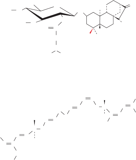
Several natural products inhibit the ATP–ADP translo-
cator. Atractyloside (a poison produced by the Mediter-
ranean thistle Atractylis gummifera that was known to the
ancient Egyptians) and its derivative carboxyatractyloside
(CATR) inhibit the process only from the external surface
of the inner mitochondrial membrane; bongkrekic acid (a
product of the bacterium Pseudomonas cocovenenans)
exerts its effects only on the internal surface.
O
O
O
C
H
O
CH
2
CH
3
CH
3
CH
3
H
2
C
H
2
C
H
3
C
CH
2
CH
2
CH
2
COOH
OCH
3
H
3
C
CH
HC C
C
C
C
H
C
H
C
H
C
H
CCOOH
HC C
H
C
C
H
C
H
H
C
H
H
C
H
R
COOH
HOOC
H
3
C
CH
2
OH
–
O
3
S
–
O
3
S
CH
2
OH
3
2
1
4
O
O
R = H Atractyloside
R = COOH Carboxyatractyloside
Bongkrekic acid
These differentially acting inhibitors have been valuable
tools in the isolation of the ATP–ADP translocator and in
the elucidation of its mechanism of action.For example,the
translocator has been purified by affinity chromatography
(Section 6-3C) using atractyloside derivatives as affinity
ligands.Atractyloside binding is also a convenient means of
identifying the translocator.
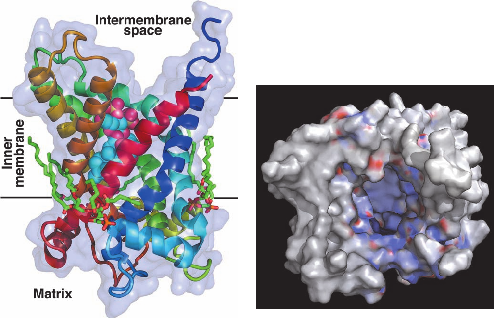
The ATP–ADP translocator, a dimer of identical ⬃300-
residue subunits, has characteristics similar to those of
other transport proteins. It has one binding site for which
ADP and ATP compete. It has two major conformations,
one with its ATP–ADP binding site facing the matrix, and
the other with this site facing outward. In its X-ray struc-
ture in complex with CATR (Fig. 20-31), determined by
Eva Pebay-Peyroula, each subunit’s six transmembrane
helices surround a deep cone-shaped cavity open to the
matrix that is occupied by the CATR.The translocator is an
antiport because it must bind ligand to change from one
conformational state to the other at a physiologically rea-
sonable rate.
The ATP–ADP translocator is not itself an active trans-
port system. However, its electrogenic export of one nega-
tive charge per transport cycle in the direction of ATP
export–ADP import is driven by the membrane potential
difference, ⌬⌿, across the inner mitochondrial membrane
(positive outside).This results in the formation of gradients
in ATP and ADP across the membrane.
5 NEUROTRANSMISSION
In higher animals, the most rapid and complex intercellular
communications are mediated by nerve impulses. A neu-
ron (nerve cell; e.g., Fig. 1-10d) electrically transmits such a
signal along its highly extended length (its axon, which is
commonly over 1 m in larger animals) as a traveling wave
of ionic currents. Signal transmission between neurons, as
well as between neurons and muscles or glands, is usually
chemically mediated by neurotransmitters. In this section
we discuss both the electrical and chemical aspects of nerve
impulse transmission.
A. Voltage-Gated Ion Channels
Ion gradients across cell membranes, as we have seen, are
generated by specific energy-driven pumps (Section 20-3).
These ion gradients are, in turn, discharged through ion
channels such as K
⫹
channels (Section 20-2F). However,
the pumps cannot keep up with the massive fluxes of ions
passing through the channels. Hence ion channels are nor-
mally shut and only open transiently to perform some spe-
cific task for the cell. The opening and closing of ion chan-
nels, a process known as gating, occurs in response to a
variety of stimuli:
1. Ligand-gated channels open in response to extracellu-
lar stimuli.For example,the KcsA K
⫹
channel (Section 20-2F)
opens when the extracellular pH is less than ⬃4 (the X-ray
structure in Fig. 20-12 is that of its closed conformation),
Section 20-5. Neurotransmission 771
JWCL281_c20_744-788.qxd 6/4/10 12:18 PM Page 771
whereas the ligand-gated ion channels in nerve cells open
on extracellularly binding specific neurotransmitters (Sec-
tion 20-5C).
2. Signal-gated channels open on intracellularly bind-
ing a second messenger such as Ca
2⫹
ion or the G
␥
subunit
of a heterotrimeric G protein (Section 19-2C).
3. Mechanosensitive channels open under the influence
of stretch, pressure, or displacement. In bacteria, these ap-
pear to function as safety valves to relieve high internal os-
motic pressures that would otherwise burst the cell wall,
whereas in animals they are important in such sensory
functions as touch and hearing.
4. Voltage-gated channels open in response to a change
in membrane potential. Multicellular organisms contain
numerous varieties of voltage-gated channels. For exam-
ple, nerve impulses arise from the sequential opening of
voltage-gated channels along the length of a single nerve
cell (Section 20-5Ba).
a. Voltage Gating in Kv Channels Is Triggered by the
Motion of a Positively Charged Protein Helix
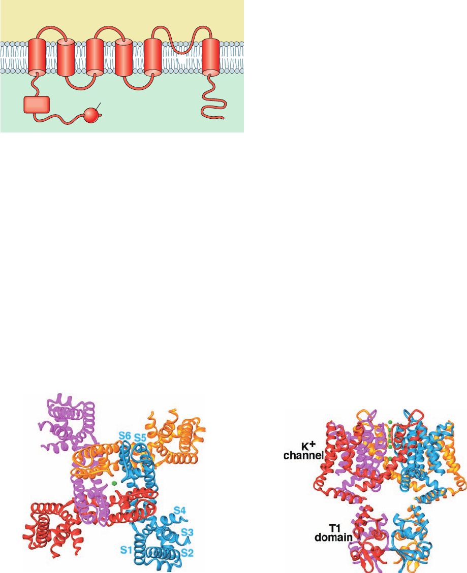
All voltage-gated K
⫹
channels are transmembrane ho-
motetramers, each subunit of which contains an ⬃220-
residue N-terminal cytosolic segment, an ⬃250-residue
transmembrane segment consisting of six helices, S1 to
S6, and an ⬃150-residue C-terminal cytosolic segment
(Fig.20-32).S5 and S6 are homologous to the KcsA channel’s
outer and inner helices (Fig. 20-12a), with their intervening
so-called P loop containing the K
⫹
channel’s TVGYG signa-
ture sequence.
Voltage-gated Na
⫹
channels and Ca
2⫹
channels are
⬃2000-residue monomers that consist of four consecutive
domains, each of which is homologous to the K
⫹
channel
transmembrane domain, separated by often large cytosolic
loops. These domains presumably assume a pseudo-
tetrameric arrangement about a central pore resembling that
of the subunits in voltage-gated K
⫹
channels. This struc-
tural homology suggests that voltage-gated ion channels
772 Chapter 20. Transport Through Membranes
Figure 20-31 X-ray structure of bovine heart ATP–ADP
translocator in complex with carboxyatractyloside. (a) A subunit
of the homodimeric protein, viewed from the plane of the inner
membrane with the intermembrane space above, is drawn in
ribbon form colored in rainbow order from its N-terminus (blue)
to its C-terminus (red) and embedded in its semitransparent
surface diagram.The carboxyatractyloside is drawn in space-
filling form with C cyan, O red, and S yellow. Three cardiolipin
(a)
(
b
)
molecules that cocrystallized with the protein are drawn in stick
form with C green, O red, and P orange. (b) The molecular
surface as viewed from the intermembrane space and colored
according to its surface charge with blue positive, white neutral,
and red negative. Note the deep positively charged cavity in
which the anionic ATP binds. [Based on an X-ray structure by
Eva Pebay-Peyroula, Université Joseph Fourier, Grenoble,
France. PDBid 2C3E.]
JWCL281_c20_744-788.qxd 7/1/10 7:19 AM Page 772
share a common architecture in which differences in ion se-
lectivity arise from precise stereochemical variations
within the central pore. However, outside of their con-
served transmembrane core, voltage-gated ion channels
with different ion selectivities are highly divergent. For ex-
ample, voltage-gated K
⫹
channels, which are known as Kv
channels, have a conserved ⬃100-residue domain, the so-
called T1 domain (Fig. 20-32), that precedes the transmem-
brane domain and that is absent in other types of voltage-
gated ion channels. The T1 domain confers specificity in
subunit oligomerization: It prevents Kv subunits of differ-
ent subfamilies from coassembling in the same tetramer.
What is the nature of the gating machinery in voltage-
gated ion channels? The X-ray structure of the rat brain Kv
channel named Kv1.2 in its open form, determined by
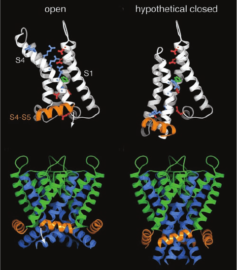
MacKinnon (Fig.20-33), reveals that its helices S1 through S4
form separate paddlelike domains that extend radially out
from the channel-forming helices, S5 and S6. The 19-residue
S4 helices, which each contain five positively charged
residues (four Arg and one Lys) spaced every ⬃3 residues,
act as voltage sensors.This was shown by covalently linking
a dye whose fluorescence spectrum varies with the polarity
of the environment to any of several residues in S4. Fluo-
rescence measurements on each of these labeled ion chan-
nels revealed that when the membrane potential decreases
(cytosol becomes more negative, which causes the channel
to close), a stretch of at least 7 residues at the N-terminal
end of S4 moves from a position near the extracellular en-
vironment to the center of the membrane. This suggests
that the five positively charged residues on the S4 helix are
drawn toward the cytosol (down in Fig. 20-34a,b) by ⬃15 Å,
pushing down on the S4–S5 linker helix, which in turn
pushes down on the S6 helix, thus collapsing together the
ends of the S6 helices so as to close the cytosolic entrance
to the K
⫹
channel (Fig. 20-34c,d).
b. The Kv Channel Has Two Gates
Electrophysiological measurements indicate that, a few
milliseconds after opening, the Kv channel spontaneously
(without a further change in membrane potential) closes, a
process termed inactivation, and does not reopen until af-
ter the membrane has repolarized (regained its resting
membrane potential). Evidently, the Kv channel contains
two voltage-sensitive gates, one to open the channel on an in-
crease in membrane potential and one to close it a short time
Section 20-5. Neurotransmission 773
Figure 20-32 Secondary structure and membrane orientation
of voltage-gated K
⫹
channels.
Figure 20-33 X-ray structure of the Kv1.2 voltage-gated K
⫹
channel. (a) View along the tetrameric protein’s 4-fold axis from
the extracellular side of the membrane in which it is embedded.
Each of its four identical subunits is colored differently, and
the T1 domain has been omitted for clarity.The fragmented
appearance of the polypeptide chains is due to the high
mobilities of the missing segments.The S5 and S6 helices with
their intervening P loops form the pore for K
⫹
ions (delineated
by green spheres). Helices S1 to S4 form a separate intramem-
brane voltage-sensing domain that associates with the S5 and S6
+
+
+
+
+
+
Inside
Outside
T1
S6
Inactivation ball
N
C
S1 S4 S5S3S2
P
(a)
(b)
helices of the clockwise adjacent subunit. (b) View perpendicular
to that in Part a with the extracellular side of the membrane
above. The pore and voltage sensing domains span a distance of
⬃30 Å, the thickness of the membrane’s hydrophobic core. The
T1 domain, which occupies the cytoplasm, forms the vestibule of
the transmembrane K
⫹
channel.The four large openings
between the T1 domain and the K
⫹
channel are the portals
through which K
⫹
ions enter the K
⫹
channel. [Based on an X-ray
structure by Roderick MacKinnon, Rockefeller University.
PDBid 2A79.]
JWCL281_c20_744-788.qxd 7/1/10 12:22 PM Page 773
later, a phenomenon that has important consequences for
the transmission of nerve impulses (Section 20-5B). In fact,
minute “gating currents” arising from the movements of
these positively charged gates in opening and closing can
be detected (electrical current is the movement of charge)
if the much larger currents of K
⫹
ions through the mem-
brane are first blocked by plugging the Kv channel from its
cytosolic side by high concentrations of Cs
⫹
or tetraethyl-
ammonium ions (which are too large to pass through the
K
⫹
pore but apparently become stuck within it).
c. Inactivation Occurs through the Insertion of the Kv
Channel’s N-Terminal Peptide into Its Central Pore
The inactivation of the Kv channel is abolished by pro-
teolytically excising its N-terminal ⬃20-residue segment
(its inactivation peptide), which NMR studies indicate
forms a ball-like structure. However, when chemically syn-
thesized inactivation peptide is injected into the cytosol,
the truncated Kv channel inactivates at a rate proportional
to the concentration of inactivation peptide. This suggests
that inactivation occurs when the inactivation ball swings
around at the end of the ⬃65-residue peptide linking it to
the T1 domain so as bind to the open K
⫹
pore in a way that
physically blocks the passage of K
⫹
ions—the so-called
ball-and-chain mechanism. Indeed, the time the Kv chan-
nel stays open varies with the length of this “chain,” as mu-
tationally adjusted.
Where is the inactivation peptide’s binding site? Muta-
tional analysis by MacKinnon revealed that the hydropho-
bic residues lining the Kv channel’s internal pore and cen-
tral cavity form the receptor site for the inactivation
peptide. Since the ⬃6-Å-diameter cytosolic entrance to the
internal pore is too narrow to admit the ball, the ball pep-
tide must unfold in order to enter the internal pore. The
first 10 residues of ball peptides are predominantly hy-
drophobic, whereas the succeeding 10 residues are largely
hydrophilic and contain several basic residues. It therefore
appears that inactivation occurs through the binding of the
N-terminus of the fully extended inactivation peptide in-
side the internal pore via hydrophobic interactions, an as-
sociation that is augmented by the binding of the basic
residues in the ball peptide’s C-terminal segment to the
acidic residues lining the entrance of the internal pore.
Thus, the inactivation peptide acts more like a snake than a
ball and chain.
How does the inactivation peptide gain access to the inter-
nal pore, which appears to be covered by the T1 tetramer?
The passage through the center of the T1 tetramer, as seen
in its X-ray structure (Fig. 20-33b), is too narrow to permit
the passage of the inactivation peptide. Moreover, Christo-
pher Miller eliminated the possibility that the individual T1
domains in a tetramer can ever separate far enough to ad-
mit the inactivation peptide by showing that cross-linking
adjacent T1 domains by genetically engineered disulfide
bonds (whose positions were selected by referring to the
T1 X-ray structure) does not significantly affect the Kv
channel’s gating properties. This strongly suggests that the
inactivation peptide gains access to the bottom of the
transmembrane pore through lateral windows between the
transmembrane and T1 domains, whose sides are formed
by the ⬃35-residue peptide segment linking these domains.
Presumably, K
⫹
ions pass through these same windows
when the Kv channel is open.
A Kv channel engineered so that only one subunit has
an inactivation peptide still inactivates but at one-fourth
the rate of normal Kv channels. Apparently, any of the nor-
mal Kv channel’s four inactivation peptides can block the
774 Chapter 20. Transport Through Membranes
(a)
(c)
(d)
(b)
Figure 20-34 Proposed mechanism of voltage gating in the
Kv1.2 voltage-gated K
⫹
channel. (a) The voltage-sensing domain
in the X-ray structure of Kv1.2 in its open conformation as
viewed from the pore parallel to the plane of the membrane with
the extracellular solution above. The polypeptide chain is drawn
in ribbon form with helices S1 through S4 white and the S4–S5
linker helix orange. Side chains are shown in ball-and-stick form
with those of the Arg and Lys residues of S4, the so-called gating
charges, cyan, those of Asp and Glu in the so-called external and
internal clusters red, and that of Phe 233, which separates the
external and internal clusters, green. Note that the gating charges
extend upward into the extracellular solution and associate with
the external cluster. (b) The voltage-sensing domain in the
hypothetical closed conformation displayed as in Part a. S4,
together with S3, has moved downward relative to S1 and S2
toward the now more negatively charged cytosol, thereby
pivoting the S4-S5 helix in the direction of the white arrow in
Part a. Here the gating charges extend downward toward the
cytosol and associate with the internal cluster. (c) The S4–S6
linkers and the K
⫹
pore assembly, which includes helices S5 and
S6, in the X-ray structure of Kv1.2 as viewed in the opposite
direction from Part a.The S6 helices are blue, the S4–S5 linkers,
which contact S6, are orange, and the remainder of the pore
assembly is green. (d) Hypothetical model of the S4–S5 linker in
the closed conformation, displayed as in Part c, with the structure
of the K
⫹
pore assembly based on the X-ray structure of the
KscA channel (Fig. 20-12a). [Courtesy of Roderick MacKinnon,
Rockefeller University. PDBid 2R9R.]
JWCL281_c20_744-788.qxd 7/1/10 7:58 AM Page 774
channel and it is simply a matter of chance as to which one
does so. In contrast, voltage-gated Na
⫹
channels have only
a single inactivation peptide, which is located on the seg-
ment linking the Na
⫹
channel’s third and fourth homolo-
gous transmembrane domains. Consequently, a genetically
engineered cut of the peptide chain in this region abolishes
Na
⫹
channel inactivation.
B. Action Potentials
Neurons, like other cells, generate ionic gradients across
their plasma membranes through the actions of the corre-
sponding ion-specific pumps. In particular, an (Na
⫹
–K
⫹
)–
ATPase (Section 20-3A) pumps K
⫹
into and Na
⫹
out of the
neuron to yield intracellular and extracellular concentra-
tions of these ions similar to those listed in Table 20-3. The
consequent membrane potential, ⌬⌿, across a cell mem-
brane is described by the Goldman equation, an extension
of Eq. [20.3] that explicitly takes into account the various
ions’ different membrane permeabilities:
[20.8]
Here, C and A represent cations and anions, respectively,
and, for the sake of simplicity, we have made the physiolog-
ically reasonable assumption that only monovalent ions
have significant concentrations.The quantities P
c
and P
a
, the
respective permeability coefficients for the various cations
and anions, are indicative of how readily the corresponding
ions traverse the membrane (each is equal to the correspon-
ding ion’s diffusion coefficient through the membrane
divided by the membrane’s thickness; Section 20-2A). Note
that Eq. [20.8] reduces to Eq. [20.3] if the permeability coef-
ficients of all mobile ions are assumed to be equal.
Applying Eq. [20.8] to the data in Table 20-3 and assum-
ing a temperature of 25°C yields ⌬⌿ ⫽ ⫺83 mV (negative
inside), which is in good agreement with experimentally
measured membrane potentials for mammalian cells. This
value is somewhat greater than the K
⫹
equilibrium potential,
the value of ⌬⌿ ⫽ –91 mV obtained assuming the membrane
is permeable to only K
⫹
ions .The mem-
brane potential is generated by a surprisingly small imbal-
ance in the ionic distribution across the membrane: Only
⬃1 ion pair per million is separated by the membrane with
(P
Na
⫹
⫽ P
Cl
⫺
⫽ 0)
¢⌿⫽
RT
f
ln
a
P
c
[C(out)] ⫹
a
P
a
[A(in)]
a
P
c
[C(in)] ⫹
a
P
a
[A(out)]
the anion going to the cytosolic side and the cation going to
the external side.The resulting electric field is, nevertheless,
enormous by macroscopic standards: Assuming a typical
membrane thickness of 50 Å, it is nearly 170,000 V ⴢ cm
⫺1
.
a. Nerve Impulses Are Propagated by
Action Potentials
A nerve impulse consists of a wave of transient mem-
brane depolarization known as an action potential that
passes along a nerve cell. A microelectrode implanted in an
axon will record that during the first ⬃0.5 ms of an action
potential, ⌬⌿ increases from its resting potential of
around –60 mV to about ⬃30 mV (Fig. 20-35a).This depo-
larization is followed by a nearly as rapid repolarization
Section 20-5. Neurotransmission 775
Table 20-3 Ionic Concentrations and Membrane
Permeability Coefficients in Mammals
Cell Blood Permeability
Ion (mM)(mM) Coefficient (cm ⴢ s
⫺1
)
K
⫹
139 4 5 ⫻ 10
⫺7
Na
⫹
12 145 5 ⫻ 10
⫺9
Cl
⫺
4 116 1 ⫻ 10
⫺8
X
⫺a
138 9 0
a
X
⫺
represents macromolecules that are negatively charged under
physiological conditions.
Source: Darnell, J., Lodish, H., and Baltimore, D., Molecular Cell Biology,
pp. 618 and 725, Scientific American Books (1986).
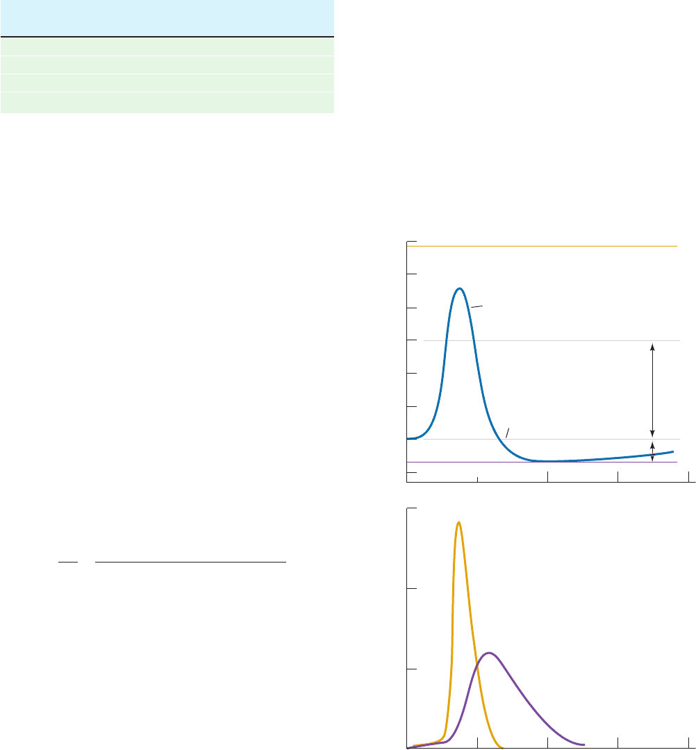
Figure 20-35 Time course of an action potential. (a) The axon
membrane undergoes rapid depolarization, followed by a nearly
as rapid hyperpolarization and then a slow recovery to its resting
potential. (b) The depolarization is caused by a transient increase
in Na
⫹
permeability (conductance), whereas the hyperpolariza-
tion results from a more prolonged increase in K
⫹
permeability
that begins a fraction of a millisecond later.The unit of conduc-
tance, 1 mho ⫽ 1 ohm
⫺1
. [After Hodgkin, A.L. and Huxley, A.F.,
J. Physiol. 117, 530 (1952).]
Na
+
equilibrium potential
Action potential
Resting potential
K
+
equilibrium potential
Hyperpolarization
Depolarization
+60
+40
+20
0
–20
–40
–60
–80
Membrane potential (mV)
30
20
10
0
0 123 4
Time (ms)
0 123 4
Time (ms)
Ionic permeabilities (mmho • cm
–2
)
K
+
permeability
Na
+
permeability
(a)
(b)
JWCL281_c20_744-788.qxd 6/4/10 1:39 PM Page 775
past the resting potential to the K
⫹
equilibrium potential
(hyperpolarization) and then a slower recovery to the
resting potential. What is the origin of this complicated
electrical behavior? In 1952, Alan Hodgkin and Andrew
Huxley demonstrated that the action potential results
from a transient increase in the membrane’s permeability
to followed, within a fraction of a millisec-
ond, by a transient increase in its permeability to K
⫹
(
Fig. 20-35b).
The ion-specific permeability changes that characterize
an action potential result from the presence of Na
⫹
- and K
⫹
-
specific voltage-gated channels. As a nerve impulse reaches
a given patch of nerve cell membrane, the increased mem-
brane potential induces the transient opening of the Na
⫹
channels, so that Na
⫹
ions diffuse into the nerve cell at the
rate of ⬃6000 ions ⴢ ms
⫺1
per channel.This increase in
causes to increase (Eq. [20.3]), which, in turn, induces
more Na
⫹
channels to open, etc., leading to an explosive
entry of Na
⫹
into the cell.Yet, before this process can equil-
ibrate at its Na
⫹
equilibrium potential of around ⬃60 mV,
the K
⫹
channels open ( increases) while the Na
⫹
chan-
nels close (inactivate; returns to its resting value).
therefore reverses sign and overshoots its resting potential
to approach its K
⫹
equilibrium value. Eventually the K
⫹
channels also inactivate and the membrane patch regains
its resting potential. The Na
⫹
channels, which remain open
only 0.5 to 1.0 ms, do not reopen until the membrane has
returned to its resting state, thereby limiting the axon’s
firing rate.
¢⌿P
Na
⫹
P
K
⫹
¢⌿
P
Na
⫹
P
K
⫹
;
Na
⫹
(P
Na
⫹
)
An action potential is triggered by an ⬃20-mV rise in
⌬⌿ to about ⫺40 mV. Action potentials therefore propagate
along an axon because the initially rising value of ⌬⌿ in a
given patch of axonal membrane triggers the action poten-
tial in an adjacent membrane patch that does so in an adja-
cent membrane patch, etc. (Fig. 20-36). The nerve impulse
is thereby continuously amplified so that its signal ampli-
tude remains constant along the length of the axon (in
contrast, an electrical impulse traveling down a wire dissi-
pates as a consequence of resistive and capacitive ef-
fects). Note, however, that since the relative ion imbal-
ance responsible for the resting membrane potential is
small, only a tiny fraction of a nerve cell’s Na
⫹
–K
⫹
gradi-
ent is discharged by a single nerve impulse (only one K
⫹
ion per 3000–300,000 in the cytosol is exchanged for ex-
tracellular Na
⫹
, as indicated by measurements with ra-
dioactive Na
⫹
). An axon can therefore transmit a nerve
impulse every few milliseconds without letup. This capac-
ity to fire rapidly is an essential feature of neuronal com-
munications: Since nerve impulses all have the same ampli-
tude, the magnitude of a stimulus is conveyed by the rate at
which a nerve fires.
b. The Voltage-Gated Na
⫹
Channel Is the
Target of Numerous Neurotoxins
Neurotoxins have proved to be invaluable tools for dis-
secting the various mechanistic aspects of neurotransmis-
sion. Many neurotoxins, as we shall see, interfere with the
action of neuronal voltage-gated Na
⫹
channels but,curiously,
776 Chapter 20. Transport Through Membranes
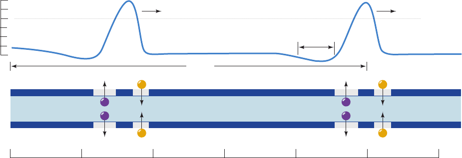
Figure 20-36 Action potential propagation along an axon.
Membrane depolarization at the leading edge of an action
potential triggers an action potential at the immediately
downstream portion of the axon membrane by inducing the
opening of its voltage-gated Na
⫹
channels.As the depolarization
wave moves farther downstream, the Na
⫹
channels close and the
K
⫹
channels open to hyperpolarize the membrane. After a brief
refractory period, during which the K
⫹
channels close and the
hyperpolarized membrane recovers its resting potential, a second
0 5 10 15 20 25 30
Na
+
Na
+
Na
+
K
+
K
+
Na
+
Membrane potential (mV)
+40
0
–40
–80
+++++++ +++
Minimum
refractory period
10 ms
cm
+++++++++++ ++++++–– ––
+++++++ ++++++++++++++ ++++++–– ––
++––––––– –––––––––––––– ––––––++
++––––––– –––––––––––––– ––––––++
impulse can follow. The indicated impulse propagation speed is
that measured in the giant axon of the squid, which, because of
its extraordinary width (⬃1 mm), is a favorite experimental
subject of neurophysiologists. Note that the action potential in
this figure appears backward from that in Fig. 20-35 because this
figure shows the distribution of the membrane potential along an
axon at an instant in time, whereas Fig. 20-35 shows the
membrane potential’s variation with time at a fixed point on the
axon.
JWCL281_c20_744-788.qxd 3/17/10 1:49 PM Page 776
few are known that affect voltage-gated K
⫹
channels.
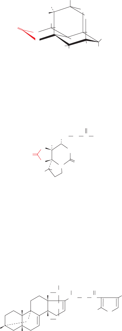
Tetrodotoxin,
a paralytic poison of enormous potency, which occurs
mainly in the skin, ovaries, liver,and intestines of the puffer
fish (known as fugu in Japan, where it is a delicacy that may
be prepared only by chefs certified for their knowledge of
puffer fish anatomy), acts by specifically blocking the Na
⫹
channel.The Na
⫹
channel is similarly blocked by saxitoxin,
a product of marine dinoflagellates (a type of plankton
known as the “red tide”) that is concentrated by filter-feeding
shellfish to such an extent that a small mussel can contain
sufficient saxitoxin to kill 50 people. Both of these neuro-
toxins have a cationic guanidino group, and both are effec-
tive only when applied to the external surface of a neuron
(their injection into the cytosol elicits no response). It is
therefore thought that these toxins specifically interact
with an anionic carboxylate group located at the mouth of
the Na
⫹
channel on its extracellular side.
Batrachotoxin,
Saxitoxin
H
N
+
N
H
H
2
N
+
NH
2
CH
2
N
N
OH
HO
H
O
C
O
NH
2
H
2
N
CH
2
OH
H
N
N
H
+
H
H
H
H
OH
H
O
O
O
–
H
HO
OH
HO
Tetrodotoxin
arrow-poison frog, Phyllobates aurotaenia, is the most po-
tent known venom (2 g ⴢ kg
⫺1
body weight is 50%
lethal in mice). This substance also specifically binds to
the voltage-gated Na
⫹
channel but, in contrast to the ac-
tions of tetrodotoxin and saxitoxin, renders the axonal
membrane highly permeable to Na
⫹
. Indeed, batra-
chotoxin-induced axonal depolarization is reversed by
tetrodotoxin.The observation that the repeated electrical
stimulation of a neuron enhances the action of batra-
chotoxin indicates that this toxin binds to the Na
⫹
chan-
nel in its open state.
Venoms from American scorpions contain families of
60- to 70-residue protein neurotoxins that also act to depo-
larize neurons by binding to their Na
⫹
channels (the differ-
ent neurotoxins in the same venom appear to be special-
ized for binding to the Na
⫹
channels in the various species
the scorpion is likely to encounter). Scorpion toxins and
tetrodotoxin do not, however, compete with each other for
binding to the Na
⫹
channel and therefore must bind at sep-
arate sites.
c. Nerve Impulse Velocity Is Increased
by Myelination
The axons of the larger vertebrate neurons are sheathed
with myelin, a biological “electrical insulating tape” that is
wrapped about the axon (Fig. 20-37a) so as to electrically
isolate it from the extracellular medium. Impulses in myeli-
nated nerves propagate with velocities of up to 100 m ⴢ s
⫺1
,
whereas those in unmyelinated nerves are no faster than
10 m ⴢ s
⫺1
(imagine the coordination difficulties that, say, a
giraffe would have if it had to rely on only unmyelinated
nerves).
How does myelination increase the velocity of nerve
impulses? Myelin sheaths are interrupted every millimeter
or so along the axon by narrow unmyelinated gaps known
as nodes of Ranvier (Fig. 20-37b), where the axon contacts
the extracellular medium. Binding studies using radioac-
tive tetrodotoxin indicate that the voltage-gated Na
⫹
channels of unmyelinated axons have rather sparse al-
though uniform distributions in the axonal membrane of
⬃20 channels ⴢ m
⫺2
. In contrast, the Na
⫹
channels of
myelinated axons occur only at the nodes of Ranvier,
where they are concentrated with a density of ⬃10
4
chan-
nels ⴢ m
⫺2
. The action potential of a myelinated axon
evidently hops between these nodes, a process named
saltatory conduction (Latin: saltare, to jump). Nerve im-
pulse transmission between the nodes must therefore oc-
cur by the passive conduction of an ionic current, a mech-
anism that is inherently much faster than the continuous
propagation of an action potential but that is also dissipa-
tive. The nodes act as amplification stations to maintain
the intensity of the electrical impulse as it travels down the
axon.Without the myelin insulation, the electrical impulse
would become too attenuated through transmembrane
ion leakage and capacitive effects to trigger an action po-
tential at the next node. In fact, multiple sclerosis, an au-
toimmune disease that demyelinates nerve fibers in the
brain and spinal cord, results in serious although rarely
fatal neurological deficiencies.
Section 20-5. Neurotransmission 777
CH
3
CH
3
H
3
C
CH
2
CH
3
H
2
C
H
2
C
H
CH
N
HO
CH
3
N
H
O
O
O
C
O
Batrachotoxin
a steroidal alkaloid secreted by the skin of a Colombian
JWCL281_c20_744-788.qxd 7/1/10 7:20 AM Page 777
C. Neurotransmitters and Their Receptors
The junctions at which neurons pass signals to other neu-
rons, muscles, or glands are called synapses. In electrical
synapses, which are specialized for rapid signal transmis-
sion, the cells are separated by a gap, the synaptic cleft, of
only 20 Å,which is spanned by gap junctions (Section 12-3F).
Hence, an action potential arriving at the presynaptic side
of the cleft can sufficiently depolarize the postsynaptic
membrane to trigger its action potential directly. How-
ever, the ⬎200-Å gap of most synapses is too large a dis-
tance for such direct electrical coupling. In these chemical
synapses, the arriving action potential triggers the release
from the presynaptic neuron of a specific substance
known as a neurotransmitter, which diffuses across the
cleft and binds to its corresponding receptors on the post-
synaptic membrane. In excitatory synapses, neurotrans-
mitter binding induces membrane depolarization, thereby
triggering an action potential on the postsynaptic mem-
brane. Conversely, neurotransmitter binding in inhibitory
synapses alters postsynaptic membrane permeability so as
to inhibit an action potential and thus attenuate excitatory
signals. What is the mechanism through which an arriving
action potential stimulates the release of a neurotransmit-
ter, and by what means does its binding to a receptor alter
the postsynaptic membrane’s permeability? To answer
these questions let us consider the workings of cholinergic
synapses; that is, synapses that use acetylcholine (ACh) as
a neurotransmitter:
Two types of cholinergic synapses are known:
1. Those containing nicotinic receptors (receptors that
respond to nicotine).
2. Those containing muscarinic receptors (receptors
that respond to muscarine, an alkaloid produced by the
poisonous mushroom Amanita muscaria).
O
Nicotine
Acetylcholine (ACh)
Muscarine
CH
2
H
3
C
CH
3
CH
2
N(CH
3
)
3
+
+
C
O
CH
2
CH
3
N(CH
3
)
3
O
H
H
HO
H
H
N
H
N
+
778 Chapter 20. Transport Through Membranes
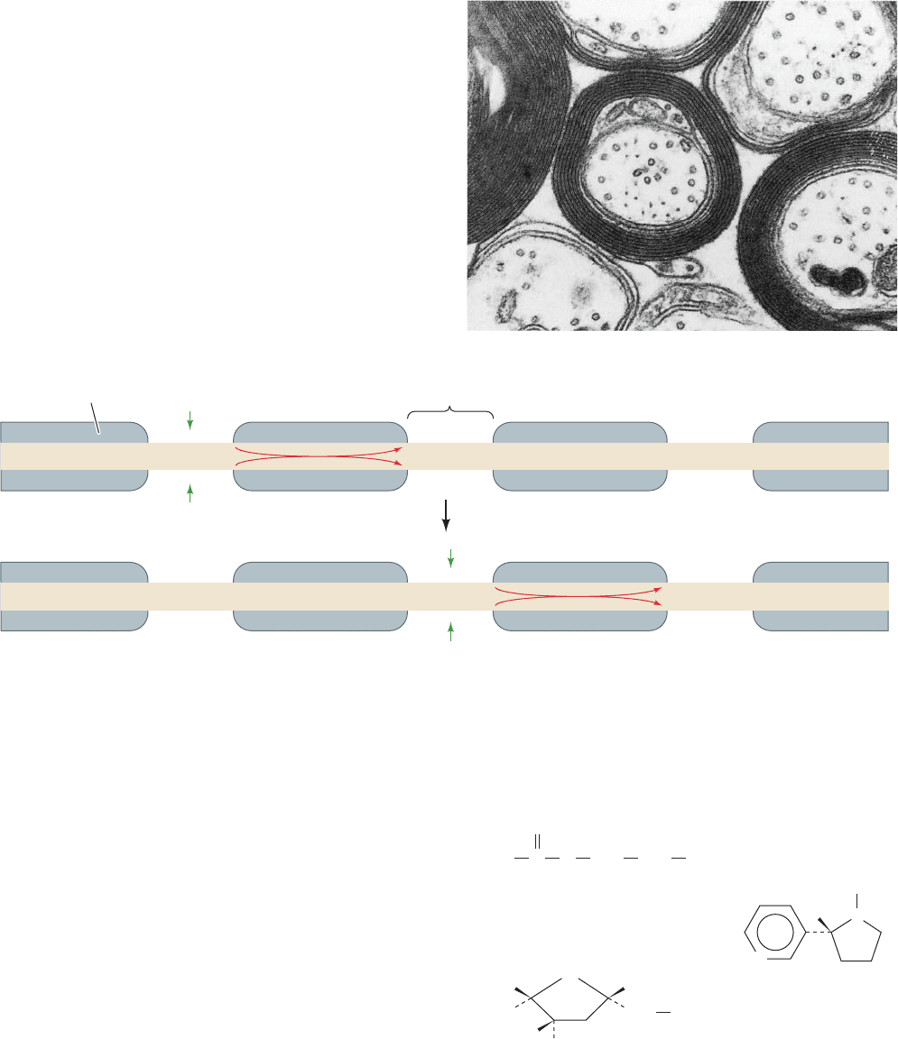
Figure 20-37 Myelination. (a) An electron micrograph of
myelinated nerve fibers in cross section.The myelin sheath
surrounding an axon is the plasma membrane of a Schwann cell,
which, as it spirally grows around an axon, extrudes its cytoplasm
from between the layers.The resulting double bilayer, which
makes between 10 and 150 turns about the axon, is a good
electrical insulator because of its particularly high (79%) lipid
content. [Courtesy of Cedric Raine,Albert Einstein College of
Medicine of Yeshiva University.] (b) A schematic diagram of a
myelinated axon in longitudinal section, indicating that in the
nodes of Ranvier (the relatively short gaps between adjacent
myelinating cells), the axonal membrane is in contact with the
extracellular medium.A depolarization generated by an action
potential at one node hops, via ionic conduction, down the
myelinated axon (red arrows), to the neighboring node, where it
induces a new action potential. Nerve impulses in myelinated
axons are therefore transmitted by saltatory conduction.
+++
+++
–––
–––
+++
–––
–––
+++
+++
–––
–––
+++
+++ +++
–––
–––
+++
–––
–––
+++
–––
+++
+++
–––
Myelin sheath
Axon
Node of
Ranvier
Na
+
Na
+
Na
+
Na
+
(b)
(a)
JWCL281_c20_744-788.qxd 6/4/10 1:23 PM Page 778
In what follows, we shall focus on cholinergic synapses con-
taining nicotinic receptors since this best characterized type
of synapse occurs at all excitatory neuromuscular junctions
in vertebrates and at numerous sites in the nervous system.
a. Electric Organs of Electric Rays Are Rich
Sources of Cholinergic Synapses
The study of synaptic function has been greatly facili-
tated by the discovery that the homogenization of nerve
tissue causes its presynaptic endings to pinch off and reseal
to form synaptosomes (Section 12-4Da). The use of synap-
tosomes, which can be readily isolated by density gradient
ultracentrifugation, has the advantage that they can be ma-
nipulated and analyzed without interference by other neu-
ronal components.
The richest known source of cholinergic synapses is the
electric organs of the freshwater electric eel Electrophorus
electricus and saltwater electric rays of the genus Torpedo.
Electric organs, which these organisms use to stun or kill
their prey, consist of stacks of ⬃5000 thin flat cells called
electroplaques that begin their development as muscle
cells but ultimately lose their contractile apparatus. One
side of an electroplaque is richly innervated and has high
electrical resistance, whereas its opposite side lacks inner-
vation and has low electrical resistance. Both sides main-
tain a resting membrane potential of around ⫺90 mV. On
neuronal stimulation, all the innervated membranes in a
stack of electroplaques simultaneously depolarize to a
membrane potential of around ⬃40 mV, yielding a poten-
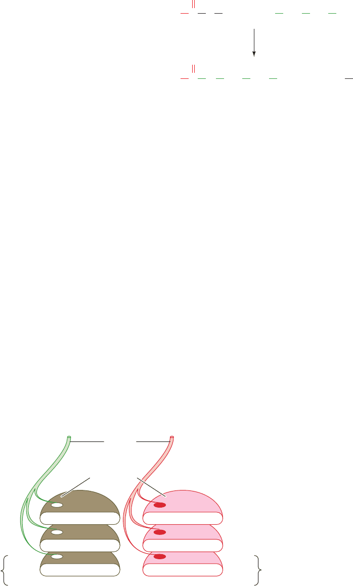
tial difference across each cell of 130 mV (Fig. 20-38). Since
the 5000 electroplaques in a stack are “wired” in series like
the batteries in a flashlight, the total potential difference
across the stack is ⬃5000 ⫻ 0.130 V ⫽ 650 V, enough to
kill a human being.
b. Acetylcholine Is Released by the Ca
2ⴙ
-Triggered
Exocytosis of Synaptic Vesicles
ACh is synthesized near the presynaptic end of a neuron
by the transfer of an acetyl group from acetyl-CoA [the
structure of coenzyme A (CoA) is given in Fig. 21-2] to
choline in a reaction catalyzed by choline acetyltransferase.
Much of this ACh is sequestered in ⬃400-Å-diameter
membrane-enveloped synaptic vesicles, which typically
contain ⬃10
4
ACh molecules each.
The arrival of an action potential at the presynaptic mem-
brane triggers the opening of voltage-gated Ca
2ⴙ
channels,
which transiently raises the local [Ca
2⫹
] from its resting level
of 0.1 M to 10 to 100 M. The resulting influx of extracel-
lular Ca
2⫹
, in turn, stimulates the exocytosis of the synaptic
vesicles in the vicinity of the Ca
2⫹
channel so that they re-
lease their packets of ACh into the synaptic cleft (Fig. 12-73).
The mechanism by which synaptic vesicles fuse with the
presynaptic membrane is discussed in Section 12-4D.
The mechanism through which Ca
2⫹
induces synaptic
vesicle exocytosis is beginning to come into focus. The ma-
jor Ca
2⫹
-sensing protein appears to be synaptotagmin I, a
protein with a single helix passing through the synaptic
vesicle membrane, whose cytosolic domain contains four
Ca
2⫹
binding sites.At resting levels of Ca
2⫹
, synaptotagmin
I binds to the Q-SNARE syntaxin (Section 12-4Db) so as
to block its binding to the R-SNARE synaptobrevin and
the Q-SNARE SNAP25,thereby preventing vesicle fusion.
However, on binding Ca
2⫹
, synaptotagmin I releases syn-
taxin, permitting vesicle fusion to commence.
Once triggered, the fusion of the synaptic vesicles with
the presynaptic membrane occurs very rapidly (in ⬍0.3 ms)
Acetyl-CoA Choline
Acetylcholine
H
3
C CoA +
+
+
C
O
HO CH
2
CH
2
N(CH
3
)
3
+
CH
2
CH
2
N(CH
3
)
3
S
Co
A
HSH
3
CC
O
O
choline
acetyltransferase
Section 20-5. Neurotransmission 779
Figure 20-38 The simultaneous depolarization (red, right) of
the innervated membranes in a stack of electroplaques “wired”
in series results in a large voltage difference between the two
++++++
+++++++
–––––––
–––––––
Motor
neuron
Electroplaques
Resting state Depolarized
130 mV
+40 mV
–90 mV
0 mV
–90 mV
–90 mV
+++++++
–––––––
–
+++++++
+++++++
+++++++ +++++++
–––––––
–––––––
––––––
++++++
–––––––
+++++++
–––––––
–––––––
+++++++
–
+++++++
–––––––
+++++++
–––––––
––––––
++
ends of the stack. This is because the total voltage across the
stack is the sum of the voltages generated by each of its numer-
ous electroplaques.
JWCL281_c20_744-788.qxd 3/17/10 1:49 PM Page 779
because many synaptic vesicles are already docked
with the presynaptic membrane. Each Ca
2⫹
pulse triggers
the exocytosis of ⬃10% of these docked vesicles. How-
ever, they are rapidly replaced because most of the re-
maining synaptic vesicles are held in reserve in a so-called
active zone within 20 nm of the presynaptic membrane.
Vesicles are held in the active zone by a fibrous phospho-
protein named synapsin I that also binds the cytoskeletal
proteins actin and spectrin (Section 12-3Db). Synapsin I
is a substrate for calmodulin-dependent protein kinase
(Section 18-3Ce), so that a rise in [Ca
2⫹
] causes its phos-
phorylation.This apparently releases the synaptic vesicles
from the active zone, thereby permitting them to dock to
the presynaptic membrane in preparation for exocytosis.
The 20-nm distance between the active zone and the
presynaptic membrane may be close enough for Q- and R-
SNAREs to initiate the formation of their coiled coil com-
plex (Fig. 12-74), which may thereby facilitate the docking
process.
The black widow spider takes advantage of this system:
Its highly neurotoxic venom protein, ␣-latrotoxin (130 kD),
causes massive release of ACh at the neuromuscular junc-
tion, in part by forming homotetrameric transmembrane
channels through the presynaptic membrane that act as
Ca
2⫹
ionophores. In contrast, botulinus toxin, as we have
seen (Section 12-4Dd), interferes with the exocytosis of
synaptic vesicles by proteolytically cleaving specific
SNARE proteins, thereby preventing ACh release.
Exocytosed synaptic vesicle proteins are rapidly recov-
ered from the presynaptic membrane via endocytosis
mainly in clathrin-coated vesicles (Section 12-4C). How-
ever, once the resulting endocytotic vesicles lose their
clathrin coats, they do not fuse with endosomes, as is usu-
ally the case (Fig. 12-91). Rather, they are immediately re-
filled with ACh by an H
⫹
–ACh antiport, which is driven by
the protons pumped into the vesicle by a V-type ATPase
(Section 20-3), and then translocated to the active zone.
This rapid recycling of the synaptic vesicles (which takes
⬍1 min) permits neurons to fire continuously at a rate of
⬃50 times per second.
c. The Acetylcholine Receptor Is a
Ligand-Gated Cation Channel
After its release at the presynaptic membrane, acetyl-
choline quickly diffuses across the synaptic cleft to the
postsynaptice membrane, where it binds to the 290-kD
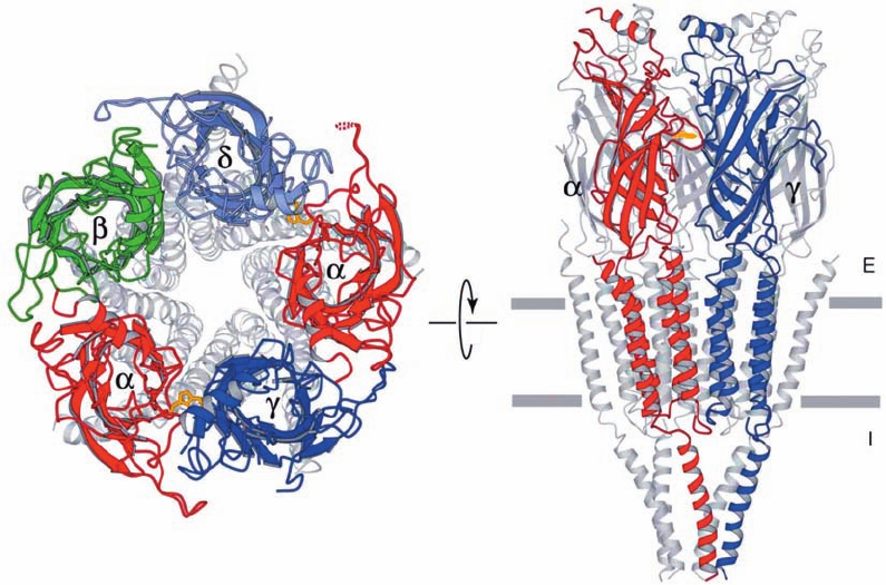
acetylcholine receptor (AChR), an ␣
2
␥␦ transmembrane
glycoprotein, whose four different ⬃490-residue subunits
are homologous. The binding of two ACh molecules to the
AChR allosterically induces the opening of a channel
through the AChR that permits Na
⫹
ions to diffuse into the
cell at a peak rate of ⬃30,000 ions per millisecond. The
780 Chapter 20. Transport Through Membranes
Figure 20-39 Electron crystal structure of the nicotinic
acetylcholine receptor from the electric ray Torpedo marmorata.
(a) View from the synaptic cleft. The extracellular domains of
each type of subunit are differently colored and their remaining
portions are gray. The side chains of ␣Trp 149, which mark the
ACh-binding sites, are drawn in stick form (gold). (b) View
(b)
(a)
parallel to the membrane with the synaptic cleft above. Only the
front two subunits are highlighted in color.The horizontal gray
bars delineate the position of the postsynaptic membrane.
[Courtesy of Nigel Unwin, MRC Laboratory of Molecular
Biology, Cambridge, U.K. PDBid 2BG9.]
JWCL281_c20_744-788.qxd 3/17/10 1:49 PM Page 780
