Teodorescu P.P. Mechanical Systems, Classical Models Volume II: Mechanics of Discrete and Continuous Systems
Подождите немного. Документ загружается.

wherefrom
()
23
sin cos secψω ϕω ϕ θ=+
,
23
cos sinθω ϕω ϕ=−
,
()
12 3
sin cos tanϕω ω ϕω ϕ θ=+ +
.
(14.2.36')
The angles
ψ, θ and ϕ are measured by the gyrocompass, the angular velocity being
then given by (14.2.36). With the aircraft instruments one can also measure the
components
Ci
v
′
of the velocity
C
′
v in the frame
′
R
, along the axes of the frame R,
the formula
ij
Cj Ci
Vvβ
′′
=
, 1, 2, 3j = , allowing then to pass to the axes of the frame
′
R ; integrating the system of equations d/d
j
Cj
tVρ
′′
= , 1, 2, 3j = , we determine the
motion of the mass centre C in the latter frame of reference.
The equations (14.1.48), (14.1.52) take the form (
23 12
0II==, because the plane
13
Cx x is a plane of symmetry)
()
23 1
132
sin
CCC
Mv v v Mg Rωω θ
′′′
+− =− +
,
()
31 2
213
cos sin
CCC
Mv v v Mg Rωω θϕ
′′′
+− = +
,
()
12 3
321
cos cos
CCC
Mv v v Mg Rωω θϕ
′′′
+− = +
,
(14.2.37)
()
11 1 31 3 33 22 2 3 31 1 2
1
C
II II I Mωω ωωωω++− + =
,
()
()
22
22 2 11 33 3 1 31 3 1
2
C
III I Mωωωωω+− + −=
,
()
33 3 31 1 22 11 1 2 31 2 3
3
C
II II I Mωω ωωωω++− − =
,
(14.2.37')
263
14 Dynamics of the Rigid Solid
where
M=Gg is the weight of the airplane, while
()
,
C
′
=
RR vω and
()
,
CCC
′
=
MM vω are the components of the torsor of the aerodynamic actions at C.
We notice that components of a pseudomoment of momentum
O
K can intervene too,
leading to supplementary terms of the form
O
O
k
ij
ijk
KKω+∈
, 1, 2, 3i = , in the left
member of the equations (14.2.37'), due to the rotation of some parts of the airplane
(e.g., of a wing of it); thus, in the right member of the same equations appear
supplementary moments, called moments of gyration. In any case, in a leeway (drift
angle) navigation we have
O
=K0.
The airplane can change its direction of advance modifying the angle between the
fixed and the movable surfaces by which its wings are fitted out; the movable surfaces
(called ailerons) corresponding to the frontal wings are coupled so that if one of them is
moving upwards the other one is moving downwards, acting thus upon the rolling axis
2
Cx . The horizontal empennage (the movable part of which is called depth rudder) and
the vertical empennage (the movable part of which is called direction) are at the back
part of the airplane, helping – as well – to change its direction. We denote by
ψ
′
the
angle between the horizontal empennage and the depth rudder, by
θ
′
the angle between

the vertical empennage and the direction and by
ϕ
′
the angle between the wing and the
aileron; one can establish the driving (manoeuvre) equations
()
()
11 23 13121
132 1
CCC d
IMev v v J RRψωωωωω
′′′′ ′
++−+−=+
,
()
()
22 31 2123
213CCC
IMev v v Jθωωωωω
′′′′
−+−−+
()
23 1 2
2
d
JRRωω ω
′
−−=+
,
()
332313
3
2
d
IJ RRϕωωω
′′
++=+
,
(14.2.38)
where
,
kk
IJ, 1, 2, 3k = , and J are axial and centrifugal moments of inertia,
respectively, of some movable parts (e.g.,
1
I is the moment of inertia of the depth
rudder with respect to its axis of rotation),
1
M and
2
M ,
1
e and
2
e are the masses and
the eccentricities of the depth rudder and of the direction, respectively,
k
R
′
are the
aerodynamic forces which appear due to these rotations, while
dk
R ,
1, 2, 3k =
, are the
corresponding driving actions. To determine the 12 unknown functions
()
Ck Ck
vvt
′′
=
,
()
kk
tωω= ,
1, 2, 3k =
, ()tψψ= , ()tθθ= , ()tϕϕ= , ()tψψ
′′
= , ()tθθ
′′
=
and ()tϕϕ
′′
= we have thus at our disposal the system of 12 differential equations
(14.2.36')-(14.2.38), corresponding to a given command. In particular problems, these
equations can be simplified (e.g., in case of dynamic equilibrated commands we have
123
0JJJJ====,
12
0ee==, while in problems of stability with free wings
we put
123
0
ddd
RRR===).
Besides the aerodynamic and manoeuvre loads, one can take into consideration the
storm loads (of aerodynamical nature too), the loads which arise at take-off and
landing, various types of loads with a local character etc.
264
MECHANICAL SYSTEMS, CLASSICAL MODELS
In case of the plane-parallel motion, the problem in the preceding subsection is
considerably simplified; we put thus in evidence the motion in the symmetry plane of
the airplane, which is a vertical plane. Unlike the general case, we report the motion to
the inertial frame of reference
12
Oxx
′′′
(the
1
Ox
′′
-axis being horizontal) and to a non-
inertial frame
12
Cx x , with the axes parallel to those of the inertial one. At the mass
centre C, which moves with the velocity
C
′
v , which makes the angle α with the
longitudinal axis
Δ of the airplane, acts the own weight
M=Gg
, the propelling force
F and the torsor
{
}
,
C
RM of the aerodynamic forces exerted upon the aircraft’s
surface. It is convenient to decompose the resultant of the aerodynamic forces in the
form
=+RWN, where W (the so-called resistance) is along the velocity
C
′
v , while
N (force of uplift) is normal to W (Fig. 14.19a). The magnitudes of these components
are obtained by studies of aerodynamical nature, in the form
2
()
2
WC
WC Av
g
γ
α
′
=
,
2
()
2
NC
NC Av
g
γ
α
′
=
,
(14.2.39)
14.2.2.5 Plane-Parallel Motion of the Airplane
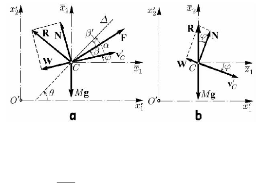
where A is the area of the lifting surface,
γ is the unit weight of the air, while the
coefficients of resistance
()
W
C α and ()
N
C α , characteristic for each airplane, are two
non-dimensional functions of angle
α; we assume that for 0α = we have
()
00
N
C = , hence 0N = , the velocity
C
′
v being along the longitudinal axis of the
aircraft.
The motion of the aircraft’s centre of mass will be specified by the equation
2
2
d
d
MM
t
′
=+++
g
FNW
ρ
,
(14.2.40)
written with respect to the inertial frame of reference
′
R
, and its rotation by the
equation
265
Fig. 14.19 Plane-parallel motion of an airplane
14 Dynamics of the Rigid Solid
CC
IMθ =
,
(14.2.40')
where
()tθθ= is the angle made by the longitudinal axis Δ with the
1
Ox
′′
-axis, while
C
I and
C
M correspond to the
3
Cx -axis, normal to the considered vertical plane. The
magnitude of the moment
C
M is obtained, by aerodynamical research too, in the form
2
(,)
CC
Mmvnvαδ θ
′
=− −
,
(14.2.39')
where the function
(,)m αδ , of the nature of a mass, depends on α and on the angle δ
made by the altitude rudder with its normal position, while the coefficient n, of the
nature of a product of a mass by a length, is due to the motion of the rudder surfaces
(the damping action of the moment
C
M ); here too, m and n are characteristics of each
aircraft. We obtain thus three scalar equations (14.2.40), (14.2.40') for the unknown
functions
11
()tρρ
′′
= ,
22
()tρρ
′′
= and ()tθθ= .
If the airplane advances with switched off motor (
=F0) and constant velocity
const
C
′
=
v
(case of a gliding flight), then the equation (14.2.40) leads to
M ++ =gNW0
. (14.2.41)
Hence, the resultant
R of the aerodynamic forces equilibrates the weight of the aircraft
(
M=−Rg). The soaring angle ϕ, made by the velocity
C
′
v with the horizontal axis
1
Cx (Fig. 14.19b), is given by tan / /
WN
WN C Cϕ =− =− , where we took into
account (14.2.39); analogously, starting from the relation
22222
GMgNW==+,
the magnitude of the soaring velocity
C
′
v is given by
2
2
22
2
C
WN
Mg
v
AC Cγ
′
=
+
.
(14.2.41')
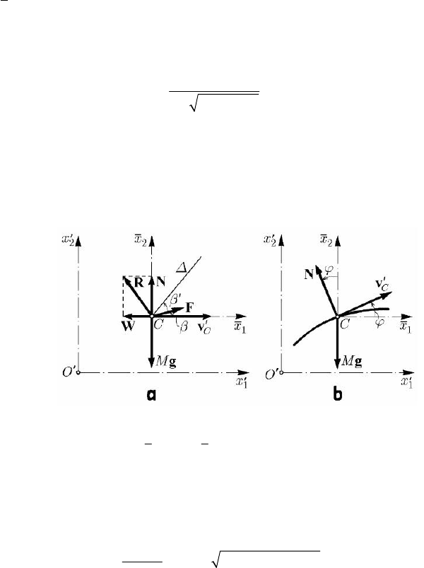
In case of a normal flight (horizontal flight with constant velocity) we have
0ϕ =
and const
C
v
′
=
; the equation (14.2.40) takes the form
M +++ =gFNW0. (14.2.42)
266
MECHANICAL SYSTEMS, CLASSICAL MODELS
In projection on the axes
1
Cx and
2
Cx , we get (Fig. 14.20a)
cos 0WF β−+ =, sin 0NGF β−+ =, (14.2.42')
where
β is the angle made by the force F with the velocity
C
′
v . We obtain thus
tan
GN
W
β
−
= ,
()
2
2
FGNW=−+.
(14.2.42'')
We can easily calculate the angle
αββ
′
=+
, because the angle
β
′
between the force
F and the longitudinal axis Δ is known. Observing that constθ = , from the equations
(14.2.39'), (14.2.40') it results
(,) 0m αδ = , determining thus δ, that is the necessary
deviation angle of the altitude rudder.
Fig. 14.20 Case of a horizontal flight with constant velocity

Lanchester studied in 1909 the motion of an aircraft with switched of motor (
=F0)
and with a nearly vanishing resultant (
≅W0), the velocity
C
′
v of which makes a
constant angle with the longitudinal axis (
constα = ). It results the equation of motion
of the mass centre
2
2
d
d
MM
t
′
=+
gN
ρ
.
(14.2.43)
Projecting on the direction of the velocity
C
′
v and on a direction normal to it, we obtain
(using the expressions (5.1.14) of the velocity in polar co-ordinates (Fig. 14.20b)
d
sin
d
C
v
g
t
ϕ
′
=− ,
2
d
cos
d
C
vgKv
t
ϕ
ϕ
′
=− +
,
(14.2.43')
where
/2
N
KCAMgγ= is a coefficient of the nature of the inverse of a length. We
have thus
d/d sin
CC
vv s g ϕ
′′
=− for an element of arc along the trajectory of the
centre C; observing that
2
ddsinxsϕ
′
= , it results
267
14 Dynamics of the Rigid Solid
2
2
2
2
C
h
vgx
M
′′
=− +
,
(14.2.44)
where h is the energy constant (corresponding to the first integral of the kinetic energy).
Observing that
2
2
d/d sind/d
CC
vtv xϕϕϕ
′′ ′
= and taking into account (14.2.44), we
can write the second equation (14.2.43') in the form
()
22
dcos cos
0
d2
Mg
K
xhMgx
ϕϕ
−+=
′′
−
.
The change of variable
1
xx
′
=
,
2
/yhMgx
′
=−
(one passes to a left-handed inertial
frame of reference Oxy , with the Oy -axis along the ascendent vertical and with the
Ox -axis at a level at which, in conformity to the formula (14.2.44), the velocity of the
mass centre vanishes) leads to
dcos cos
d2
K
yy
ϕϕ
+=
,
wherefrom
2
cos
a
by
y
ϕ =+,
2
3
bK= , ,constab= .
(14.2.45)
Observing that
()
()
1/2 1/2
22 2
dd 1
cos
d
dd
1d/d
xx
s
xy
yx
ϕ == =
+
⎡
+⎤
⎣
⎦
,
we obtain the differential equation of the trajectory of the mass centre in the form
()
2
d
2
1
d
y
a
by
xy
+=+
.
Differentiating with respect to the variable x, we obtain
()
22
3/2
2
d/d
1
1d/d
yx
a
b
Ryy
yx
== −
⎡+ ⎤
⎣⎦
,
(14.2.45')
where R is the curvature radius of the trajectory at the point C. Using the relations
(14.2.45), (14.2.45'), one obtains the trajectory by a graphical integration; the curve
thus obtained is called a figoid, the corresponding motion being a figoidal motion.
268
MECHANICAL SYSTEMS, CLASSICAL MODELS
Let be a homogeneous circular cylinder of radius R and weight
M=Gg, situated on
a plane inclined with the angle
α with respect to the horizontal; considering the
plane-parallel motion of the cylinder, it is sufficient to make a study in a vertical plane,
which passes through the mass centre of the cylinder (Fig. 14.21). Assuming at the
beginning that sliding friction does not exist, the circular disc of radius R (to which is
reduced the cylinder in our study) glides downwards in a uniform accelerated motion,
under the action of the own weight
G and of the constraint force N. Writing the
equations of motion of the mass centre in the inertial frame of reference
12
Oxx
′′′
, we
find the magnitude of the normal constraint force
cos cosNG Mgαα== , (14.2.46)
as well as
d/d sin
C
Mv t G α
′
= , wherefrom d/d sin
C
vtgα
′
= . Hence, the centre C
moves frictionless as a heavy particle of mass M on a plane inclined by the angle
α
with respect to the horizontal; its trajectory is, obviously, the
1
Cx -axis, the disc having
a motion of translation, while the component of
′
ρ
along the
1
Ox
′′
-axis is given by
()
20
11
/2 singtραρ
′′
=+
, where
0
1
ρ
′
corresponds to the initial moment 0t = .
If a tangential constraint force
T, applied at the point I, intervenes too, the inclined
plane being rough, we obtain the equations of motion (
C
I is the moment of inertia with
respect to an axis normal at C to the fixed plane in which the motion takes place; we
use a left-handed frame of reference)
14.2.2.6 Rolling on an Inclined Plane
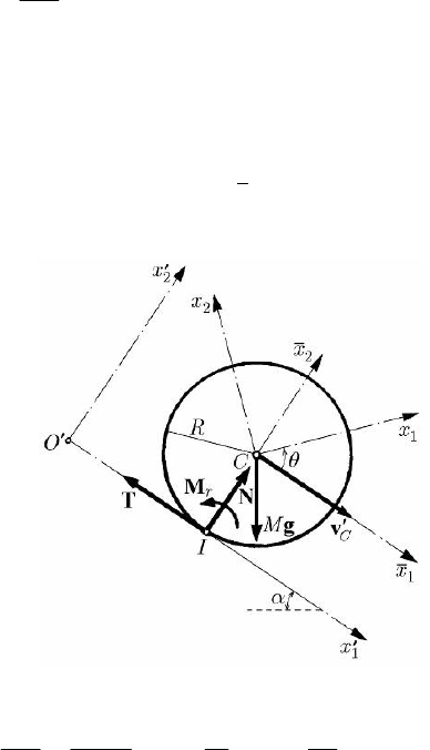
d
sin
d
C
v
MMgT
t
α
′
=−
,
C
ITRω =
,
(14.2.47)
the ideal constraint force being given by the relation (14.2.46) too; here is the angular
velocity by which the disc is rolling without sliding on the inclined plane and we have
C
vRω
′
= , I being the instantaneous centre of rotation. We notice also that
()
0
11 0
Rρρ θθ
′′
=+ −
, where
0
θ corresponds to the initial moment 0t = , being the
angle made by the
1
Cx -axis with the
1
Cx -axis. Hence,
()
2
/d/d
CC
TIRvt
′
= ;
replacing in the first equation (14.2.47), it results
269
14 Dynamics of the Rigid Solid
ω
d
sin
d1
C
v
g
t
α
λ
′
=
+
,
m
M
λ =
,
2
C
I
m
R
=
(14.2.48)
for the rolling without sliding, where m is the peripheral mass of the disc (the mass
which, situated at the distance R from the centre C, leads to the axial moment of inertia
C
I
). Observing that
2
/2
C
IMR= , it results 1/2λ = . If the disc is reduced to a
peripheral circle of mass M (corresponds to a hollow cylinder, with a very thin wall),
then we have
1λ = . We can thus state that a homogeneous full cylinder is rolling
without sliding on the inclined plane with an acceleration greater (hence, quicker) than
that of the hollow cylinder, assuming that both cylinders are rolling without initial
velocity.
Studying, analogously, the rolling without sliding of a homogeneous sphere in a
vertical plane, which contains its centre of mass, we notice that
2
2/5
C
IMR=
; we
find thus
2/5λ = , the corresponding acceleration being greater than the acceleration
of the two cylinders. Observing that
()
[]
20
11
/2 1 singtρλαρ
′′
=+ + and denoting
Fig. 14.21 Rolling on an inclined plane
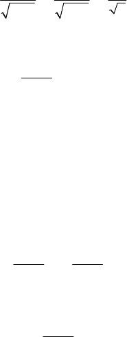
by
cf
t ,
ch
t ,
s
t and
p
t the times in which a full and a hollow cylinder, a sphere and a
particle, respectively, are rolling without sliding on the same inclined plane, without
initial velocity, travelling through the same space, we obtain
s
cf ch
p
2
7/5 3/2
t
t
t
t ===
.
(14.2.49)
The tangential constraint force is given by
sin
1
TMg
λ
α
λ
=
+
.
(14.2.50)
270
MECHANICAL SYSTEMS, CLASSICAL MODELS
The above results hold also for a rigid solid with an axis of geometric and mechanical
symmetry and with a plane of geometric and mechanical symmetry, normal to that axis
(including thus also the case of a non-homogeneous rigid solid).
To have a rolling without sliding, it is necessary that
TfN≤
, where tanf ϕ= is
the coefficient of sliding friction, while
ϕ is the angle of sliding friction between the
cylinder and the inclined plane; hence, the condition of rolling without sliding of the
cylinder is
11
tan tanf
λλ
αϕ
λλ
++
≤=
(14.2.51)
or
αϕ
′
≤ ,
1
tan tan
λ
ϕϕ
λ
+
′
=
, ϕϕ
′
> .
(14.2.51')
Corresponding to the results in Chap. 4, Subsecs 1.1.8 and 2.1.6 too, a particle would
slide on the inclined plane if
ϕα< ; if αϕ
′
> , the cylinder is rolling with sliding.
Experimentally, one sees firstly that, for a sufficiently small angle
α, the cylinder
remains at rest, due to the apparition of a moment of rolling friction
r
M , which equates
to zero the couple TR ; observing that, in this case,
0
C
v
′
= , the first equation (14.2.47)
gives
sinTMg α= , so that the respective couple will be sin tanMgR NRαα= . For
an angle
0
αα> ,
0
tan
r
MNRα=
, the cylinder recommences to roll; introducing the
coefficient of rolling friction
0
tansR α=
, it results
r
MsN= , corresponding to the
considerations in Chap. 3, Subsec. 2.2.12 and Chap. 4, Subsec. 2.1.4. The experiments
show that, in general, the influence of the rolling friction is smaller than the influence of
the sliding friction and we have
0
αϕ< , hence /fsR< .
If the rolling friction appears too, then the second equation (14.2.47) is completed in
the form
C
ITRsNω =−
, (14.2.47')
so that, analogously, we obtain
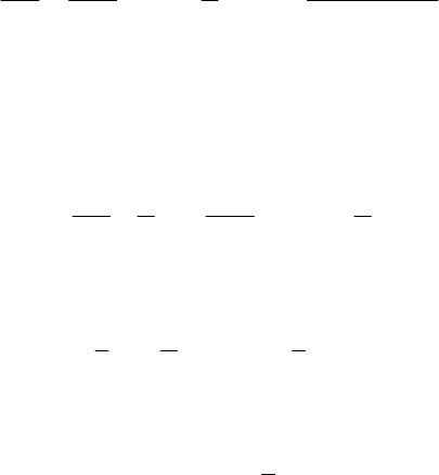
(
)
()
()
0
0
d
sin
sin cos
d1 1 cos
C
v
g
g
s
tR
αα
αα
λλα
′
−
=−=
++
.
(14.2.48')
Comparing the relations (14.2.48) and (14.2.48') and observing that
()
00
sin sin cosαα α α−< , it results that the intervention of the rolling friction
diminishes the acceleration of the mass centre of the disc. The tangential constraint
force will be given, in the same way, by
(
)
d
sin cos
d1
C
v
Mg
ss
Tm N
tR R
λα α
λ
′
=+= +
+
.
(14.2.50')
271
14 Dynamics of the Rigid Solid
The condition of rolling without sliding (
TfN≤
) becomes
(
)
()
0
11
tan tan tan tan
s
ff
R
αϕϕα
λλ
≤+ − = + −
(14.2.52)
or
αϕ
′′
≤ ,
()
0
1
tan tan tan tanϕϕ ϕα
λ
′′
=+ −
,
(14.2.52')
where we suppose that
0
ϕα> . Finally, for
0
αα≤
the disc is at rest, for
0
ααϕ
′′
<≤ the disc is rolling without sliding, while for αϕ
′′
> the rolling takes
place with sliding, assuming a null velocity at the initial moment.
The above results can be put in connection also with the study of the equilibrium
problems of the drawn and of the motive wheels (see Chap. 4, Subsec. 2.1.4).
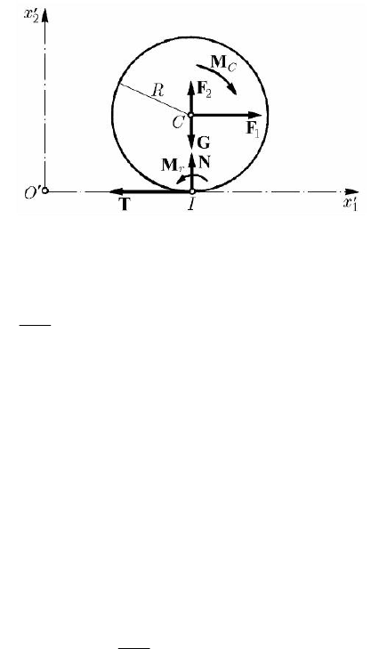
If the cylinder considered at the preceding subsection lies on a horizontal plane (the
case
0α = ), then the problem has a different character; indeed, if upon the cylinder (a
disc in a vertical cross section) acts only its own weight
M=Gg as a given force, the
initial velocity being equal to zero, this one remains at rest. To roll on the horizontal
plane, the disc must be acted upon also by other given forces (which will be considered
constant in time), of torsor
{
}
,
C
FM at the mass centre C (Fig. 14.22); as well, the
initial velocity can be non-zero. In the case of rolling without sliding, the contact point
I of the disc with the horizontal plane is the instantaneous centre of rotation, while the
velocity of the mass centre C (which moves along a horizontal) is given by
C
R
′
=v ω ,
(14.2.53)
where is the rotation angular velocity about the centre C; the relation takes place at
the initial moment
0t = too, in the form
0
0
C
R
′
=v ω . If the point I slides along the
14.2.2.7 Rolling on a Horizontal Plane
ω
1
Ox
′′
-axis with the velocity
I
′
v (the disc has a motion of translation too), then – by
composition of velocities – we can write
CI
R
′′
=+vv ω.
(14.2.53')
At the initial moment we have, obviously,
00
0
CI
R
′′
=+vv ω . In general, arises a force
of sliding friction
T, opposite to the motion (to the velocity
I
′
v ) and a moment of
rolling friction of magnitude
r
MsN= ,
0
tansR α= , which, as well, is opposite to
the motion or to the tendency of motion.
272
MECHANICAL SYSTEMS, CLASSICAL MODELS
From the theorem of motion of the mass centre, it results
1
d
d
C
v
MTF
t
′
=− +
,
2
0NGF−+ =
,
(14.2.54)
while the theorem of moment of momentum with respect to the same centre gives (we
use a left-handed frame of reference)
r
CC
IMMTR TRω =−+=+
M ,
r
C
MM=−M .
(14.2.54')
We find the normal constraint force
2
NGF=−
, (14.2.55)
where we assume that
2
GF> (otherwise, the cylinder would be detached from the
plane). Eliminating the constraint force T, it results
1
d
d
C
C
v
IMR FR
t
ω
′
+=+
M .
(14.2.56)
In case of rolling without sliding (pure rolling) we can assume that at a moment t (as
well, at the initial moment
0t = ) takes place the relation (14.2.53). The equation
(14.2.56) becomes
Fig. 14.22 Rolling on a horizontal plane
