Tarek Ahmed. Reservoir engineering handbook
Подождите немного. Документ загружается.


The conductance ratio can be expressed more conveniently in a
mathematical form as follows. For an areal sweep efficiency of
100%, i.e., E
A
= 1.0:
where γ = conductance ratio
M = mobility ratio
For 1 < E
A
< 100%:
where the coefficients a
1
through a
7
are given below:
Coefficients M < 1 M > 1
a
1
0.060635530 0.4371235
a
2
–2.039996000 0.5804613
a
3
0.025367490 –0.004392097
a
4
1.636640000 0.01001704
a
5
–0.624070600 1.28997700
a
6
–0.0002522163 0.00002379785
a
7
2.958276000 –0.015038340
Effect of Initial Gas Saturation
When a solution-gas-drive reservoir is under consideration for water-
flooding, substantial gas saturation usually exists in the reservoir at the
start of the flood. It is necessary to inject a volume of water that
approaches the volume of the pore space occupied by the free gas before
the oil is produced. This volume of water is called the fill-up volume.
Because economic considerations dictate that waterflooding should occur
at the highest possible injection rates, the associated increase in the reser-
voir pressure might be sufficient to redissolve all of the trapped gas S
gt
back in solution. Willhite (1986) points out that relatively small increases
in pressure frequently are required to redissolve the trapped gas (see Fig-
ure 14-2). Thus in waterflooding calculations, it is usually assumed that
the trapped (residual) gas saturation is zero. A description of the displace-
γ= + +
(
)
+
+
(
)
+
()
aaaEM a
M
E
aM
A
aaE
A
A
123 6
2
7
4
5
14 - 77
γ=
(
)
M14-76
968 Reservoir Engineering Handbook
Reservoir Eng Hndbk Ch 14 2001-10-25 17:38 Page 968

ment mechanism occurring under a five-spot pattern will indicate the
nature of other secondary recovery operations. The five-spot pattern uses
a producing well and four injection wells. The four injectors drive the
crude oil inward to the centrally located producer. If only one five-spot
pattern exists, the ratio of injection to producing wells is 4:1; however,
on a full-field scale it includes a large number of adjacent five spots. In
such a case, the number of injection wells compared to producing wells
approaches a 1:1 ratio.
At the start of the waterflood process in a solution-gas-drive reservoir,
the selected flood pattern is usually characterized by a high initial gas
saturation of S
gi
and remaining liquid saturations of S
oi
and S
wi
. When
initial gas saturation exists in the reservoir, Craig, Geffen, and Morse
(1955) developed a methodology that is based on dividing the flood per-
formance into four stages. The method, known as the CGM method after
the authors, was developed from experimental data in horizontal labora-
tory models representing a quadrant of a five spot. Craig et al. identified
the following four stages of the waterflood as:
1. Start—interference
2. Interference—fill-up
3. Fill-up—water breakthrough
4. Water breakthrough—end of the project
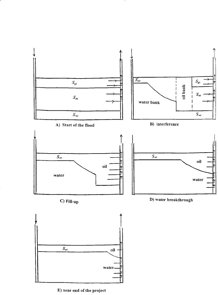
A detailed description of each stage of the flood is illustrated schemati-
cally in Figures 14-44 through 14-46 and described below:
Stage 1: Start—Interference
At the start of the water-injection process in the selected pattern area of a
solution-gas-drive reservoir, high gas saturation usually exists in the
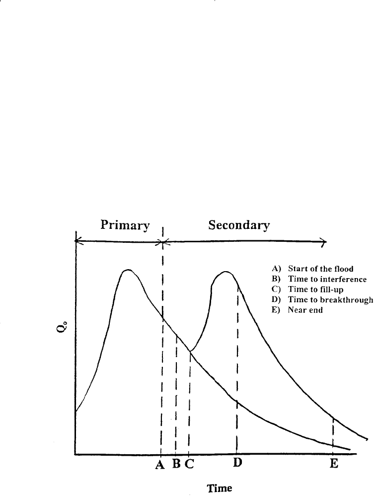
flood area as shown schematically in Figure 14-44. The current oil pro-
duction at the start of the flood is represented by point A on the conven-
tional flow rate–time curve of Figure 14-45. After the injection is initiat-
ed and a certain amount of water injected, an area of high water
saturation called the water bank is formed around the injection well at
the start of the flood. This stage of the injection is characterized by a
radial flow system for both the displacing water and displaced oil. With
continuous water injection, the water bank grows radially and displaces
the oil phase that forms a region of high oil saturation that forms an oil
Principles of Waterflooding 969
Reservoir Eng Hndbk Ch 14 2001-10-25 17:38 Page 969

Figure 14-44. Stages of waterflooding.
970 Reservoir Engineering Handbook
Reservoir Eng Hndbk Ch 14 2001-10-25 17:38 Page 970

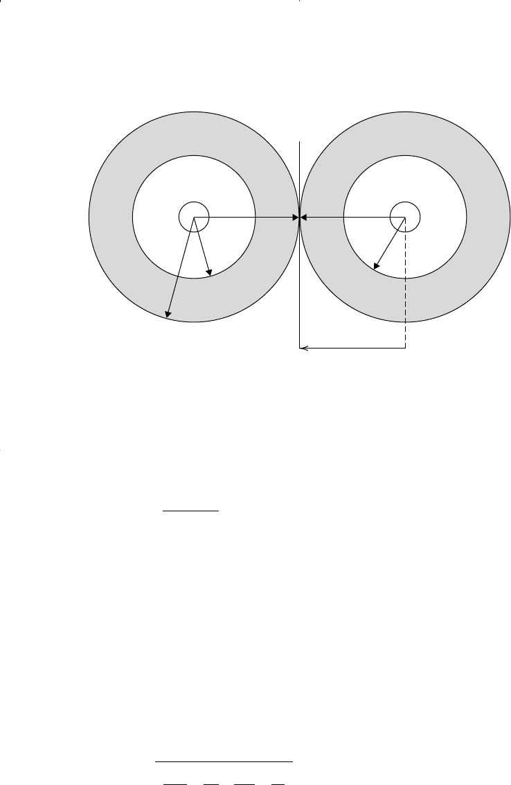
bank. This radial flow continues until the oil banks, formed around adja-
cent injectors, meet. The place where adjacent oil banks meet is termed
Interference, as shown schematically in Figure 14-46. During this stage
of the flood, the condition around the producer is similar to that of the
beginning of the flood, i.e., no changes are seen in the well flow rate Q
o
as indicated in Figure 14-45 by point B. Craig, Geffen, and Morse (1955)
summarized the computational steps during this stage of the flood, where
radial flow prevails, in the following manner:
Figure 14-45. Predicted production history.
Principles of Waterflooding 971
Reservoir Eng Hndbk Ch 14 2001-10-25 17:38 Page 971

Figure 14-46. Interference of oil banks.
Step 1. Calculate the cumulative water injected to interference W
ii
from
the following expression:
where W
ii
= cumulative water injected to interference, bbl
S
gi
= initial gas saturation
φ = porosity
r
ei
= half the distance between adjacent injectors, ft
Step 2. Assume several successive values of cumulative water injected
W
inj
, ranging between 0 and W
ii
, and calculate the water-injection
rate at each assumed value of W
inj
from:
i
hk P
k
r
rk
r
r
w
w
rw w
o
ro
o
=
+
(
)
0 00707. ∆
µµ
ln ln
14 - 79
W
hSr
ii
gi ei
=
(
)
πφ
2
5 615.
14 - 78
oil bank
water bank
r
r
0
r
ei
972 Reservoir Engineering Handbook
Reservoir Eng Hndbk Ch 14 2001-10-25 17:38 Page 972

where i
w
= water injection, bbl/day
P = pressure difference between injector and producer, psi
k = absolute permeability, md
k
ro
= relative permeability of oil at S
wi
k
rw
= relative permeability of water at
r
o
= outer radius of the oil bank, ft
r = outer radius of the water bank, ft
r
w
= wellbore radius, ft
The outer radii of the oil and water banks are calculated from:
The flood performance from the start to interference, i.e., stage 1,
is further discussed in the following example.
Example 14-13
Use the data given in Example 14-11 and determine the performance
of the flood from the start to interference. The following additional data
are available to reflect the assumption that a free gas exists at the start of
the flood:
Initial oil saturation S
oi
= 0.75
Initial gas saturation S
gi
= 0.15
Initial water saturation S
wi
= 0.10
Constant pressure difference ∆P = 3,000 psi
Half distance between injectors r
ei
= 660 ft
Distance between injector and producer d = 932 ft
Mobility ratio M = 0.8
E
ABT
= 0.717
Q
iBT
= 0.463
Pore volume = 310,320 bbl
rr
S
SS
o
gi
wBT wi
=
−
(
)
14 - 81
r
W
hS
o
inj
gi
=
(
)
5 615.
πφ
14 - 80
S
wB
T
Principles of Waterflooding 973
Reservoir Eng Hndbk Ch 14 2001-10-25 17:38 Page 973

Solution
Step 1. Calculate stock-tank oil in place at start of flood, NS:
Step 2. Calculate injected water at interference W
ii
from Equation 14-78:
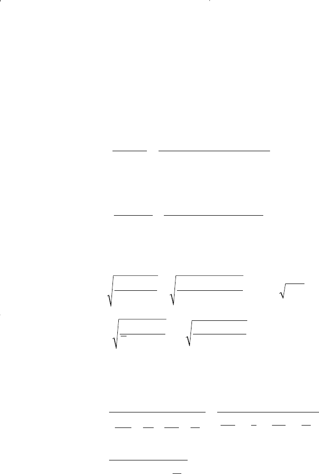
Step 3. Simplify the calculations by expressing outer radii of the oil and
water banks (Equations 14-80 and 14-81) as follows:
Step 4. Express the injectivity equation as represented by Equation 14-
79 by:
Step 5. Perform the required calculation for “stage one” in the following
tabulated form:
i
hk P
k
r
rk
r
r
rr
r
i
r
r
r
w
w
rw w
o
ro
o
o
w
o
=
+
=
(
)
(
)
(
)
+
=
(
)
+
0 00707 0 00707 5 31 5 3000
05
04 1
10
10
3 340
125
.
ln ln
..
.
.
ln
.
.
ln
,
.ln ln
∆
µµ
rr
S
SS
rr
o
gi
wBT wi
oo
=
−
=
−
=
015
0 563 0 10
0 562
.
..
.
r
W
hS
W
W
o
inj
gi
inj
inj
==
(
)
(
)
(
)
=
5 615 5 615
502015
3 452
..
..
.
πφ π
W
hSr
bbl
ii
gi ei
==
(
)
(
)
(
)
(
)
=
πφ
π
2
2
5 615
5 0 20 0 15 660
5 615
36 572
.
..
.
,
N
PV S
B
STB
S
oi
oi
=
(
)
=
(
)
−−
(
)
=
310 320 1 0 15 0 10
120
193 950
,..
.
,
974 Reservoir Engineering Handbook
Reservoir Eng Hndbk Ch 14 2001-10-25 17:38 Page 974

W
inj
(Assume) r
o
ri
w
(i
w
)
avg
t
=W
inj
/(i
w
)
avg
t=(t)
500 77.2 43.9 631.1 0.79 0.79
5,000 244.1 138 496.2 563.8 7.98 8.77
10,000 345.2 196.5 466.2 481.2 10.39 19.16
15,000 422.8 240.7 450.3 458.3 10.91 30.07
20,000 488.2 277.9 439.6 445.0 11.24 41.31
25,000 545.8 310.7 431.7 435.7 11.48 52.79
30,000 597.9 340.3 425.5 428.6 11.67 64.61
35,000 645.8 367.6 420.3 422.9 11.82 76.43
36,572 660 375.7 418.9 419.6 3.75 80.18
The above calculations indicate that time to interference t
ii
will occur
at 80.18 days after the start of the flood with a water-injection rate at
interference i
wi
of 418.9 bbl/day. Prior to oil bank interference, the injec-
tion rate i
w
(or injectivity i
w
/∆P) decreases because the radii of the oil
and water banks, i.e., r
o
and r, are continuously increasing. Notice that
the reservoir will not respond to the waterflood during this stage.
This delay in the reservoir response is mainly due to the fact that the
injected water and the displaced oil are essentially moved to fill up part
of the gas pore space. As described previously in Example 14-11, an
immediate reservoir response to the waterflood can only occur when no
gas exists at the start of the flood, i.e., S
gi
= 0.
Stage 2: Interference—Fill-Up
This stage describes the period from interference until the fill-up of the
preexisting gas space. Fill-up is the start of oil production response as
illustrated in Figure 14-44 and by point C on Figure 14-45. The flow dur-
ing this time is not strictly radial and is generally complex to quantify
mathematically. Therefore, the flood performance can only be deter-
mined at the time of fill-up.
The required performance calculations at the fill-up are summarized in
the following steps:
Principles of Waterflooding 975
Reservoir Eng Hndbk Ch 14 2001-10-25 17:38 Page 975

Step 1. Calculate the cumulative water injected at fill-up W
if
by applying
the following expression:
where W
if
= cumulative water injected at fill-up, bbl
(PV) = total flood pattern pore volume, bbl
S
gi
= initial gas saturation
The above equation suggests that while fill-up is occurring, the
oil production rate is either zero or negligible, compared with the
water injection rate. If the oil production rate Q
o
prior to fill-up
is significant, the cumulative water injected at the fill-up W
if
must be increased by the total volume of oil produced from the
start of injection to fill-up, i.e.:
where N
p
= cumulative oil production from start of flood to
fill-up, STB
B
o
= oil formation volume factor, bbl/bbl
Equation 14-83 indicates that the fill-up time will also increase;
in addition, it causes the fill-up time calculation to be iterative.
Step 2. Calculate the areal sweep efficiency at fill-up by using Equation
14-63, or:
at fill-up:
Step 3. Using the mobility ratio and the areal sweep efficiency at fill-up,
determine the conductance ratio γ from Figure 14-42 or Equation
14-77. Note that the conductance ratio can only be determined
when the flood pattern is completely filled with liquids, which
occurs at the fill-up stage.
E
W
PV S S
A
if
wBT wi
=
(
)
−
(
)
E
W
PV S S
A
inj
wBT wi
=
(
)
−
(
)
WPVS
N
B
if gi
P
o
=
(
)
+
(
)
14 - 83
WPVS
if gi
=
(
)
(
)
14 - 82
976 Reservoir Engineering Handbook
Reservoir Eng Hndbk Ch 14 2001-10-25 17:38 Page 976

Step 4. For a constant pressure difference, the initial (base) water injec-
tion rate i
base
from Equation 14-71 is:
Step 5. Calculate the water injection at fill-up i
wf
and thereafter from
Equation 14-74:
The above expression is only valid when the system is filled with liquid,
i.e., from the fill-up point and thereafter.
Step 6. Calculate the incremental time occurring from interference to
fill-up from:
The above expression suggests that the fill-up will occur after interfer-
ence.
Example 14-14
Using the data given from Example 14-13, calculate the flood perfor-
mance at fill-up. Results of Example 14-13 show:
• Time to interference t
ii
= 80.1 days
• Cumulative water injected to interference W
ii
= 36,572 bbl
• Water injection rate at interference i
wi
= 418.9 bbl/day
Solution
Step 1. Calculate the cumulative water injected at fill-up from Equation
14-81:
W PV S bbl
if gi
=
(
)
=
(
)
=310 320 0 15 46 550,. ,
∆t
WW
ii
if ii
wi wf
=
−
+
2
ii
wf
=γ
base
i
hkk P
d
r
ro
o
w
base
=
−
0 003541
0 619
.
ln .
∆
µ
Principles of Waterflooding 977
Reservoir Eng Hndbk Ch 14 2001-10-25 17:38 Page 977
