Swaminathan N., Bray K.N.C. (eds.) Turbulent Premixed Flames
Подождите немного. Документ загружается.

4.1 Application of Lean Flames in Internal Combustion Engines 293
1800
1000
Mass-Averaged Temp. (K)
Pressure (bars)
200
260 280
Crank Angle (CA)
300 340 400
1200
1400
1600
400
600
800
60
LTHR
50
40
30
20
10
0
320 360 380
PRF80, IMEPg = 539 kPa
iso-Octane, IMEPg = 395 kPa
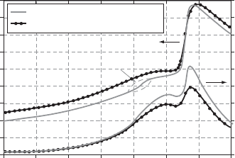
Figure 4.41. Temperature and pressure
traces for iso-octane and PRF80, (φ =
0.40) [135]. LTHR, low-temperature heat
release.
and single-stage ignition in highly branched fuel molecules, containing primary C–H
bonds that are difficult to abstract. Apart from the two major commercial fuels, gaso-
line and diesel, many other fuels have been used to fuel HCCI engines, including
mixtures of two so-called primary reference fuels (PRFs), iso-octane and n-heptane.
The advantage of PRF mixtures is that these allow a controlled parametric investi-
gation into HCCI characteristics based on reasonably well-known and understood
chemistry.
Figure 4.41 [135] shows the difference in auto-ignition, for a lean mixture, be-
tween a fuel with single-stage (iso-octane) and one with two-stage (PRF 80) ignition,
the latter showing a low-temperature heat release (LTHR) at about 340
◦
CA. The
practical importance is that, because the two-stage fuel allows a lower intake tem-
perature, a higher charge mass can be inducted into the cylinder, and hence a higher
power output is delivered. The fuel with the two-stage ignition also has smaller cycle-
to-cycle variations and can withstand greater retarding of ignition, as a consequence
of LTHR damping out random variations in intake temperature and of the enhance-
ment of intermediate-temperature chemistry that is due to the LTHR, respectively
[117]. Therefore higher loads can be delivered by fuels with some two-stage ignition
than with single-stage ignition: As discussed in [136], the limiting loads – depending
on the extent of the LTHR – can be related to either to the available oxygen because
of the amount of EGR required to retard combustion phasing or to the production
of small amounts of NO
x
that advance combustion phasing to runaway knock.
It is of fundamental as well as of practical importance (e.g., for engine control)
to know how changes in φ shift the combustion phasing. An intriguing experiment
[137] shows how to remove the thermal effects of varying φ (i.e., changes in wall
temperature and residual temperature). For two-stage fuels (but not single-stage fu-
els), φ shifts the combustion phasing. These two-stage ignition fuels become sensitive
because the intensity of the low-temperature auto-ignition reactions is proportional
to the local fuel concentration. In turn, this makes the timing of the ‘hot’ main com-
bustion event sensitive to the local φ. Therefore, introducing a range of φ in the
combustion chamber leads to a staged combustion event with lower pressure-rise
rates.
For a research-grade gasoline, the effect of intake pressure boosting is to enhance
auto-ignition, as might be expected, so that, for example, intake temperature has to
be reduced and cooled EGR has to be increasingly added [138]. The maximum gross
IMEP (over the compression and expansion strokes only) increases with boost.
294 Lean Flames in Practice
However, this is possible only by highly retarding combustion to avoid knock, and
this in turn is possible because the ‘intermediate-temperature heat release’ becomes
greatly enhanced during boosted operation. This latter is then able to counteract the
fall in temperature that is due to piston expansion during highly retarded ignition.
Fuels with a high volatility, such as gasoline, form a mixture relatively easily,
and, because this fuel exhibits only single-stage ignition, it is relatively difficult
to ignite. In contrast, diesel fuel has the opposite characteristics: It is relatively
non-volatile but is relatively easily ignited because of its cetane number through
compression ignition and its pronounced two-stage ignition and combustion. As a
consequence, combustion can easily become overadvanced. Although HCCI engines
can be run on diesel and diesel-like fuels, this combination of characteristics has
led researchers to consider an alternative, and perhaps more promising, approach
to secure low-emission, high-efficiency combustion. Here we refer to this as low-
temperature combustion (LTC) and consider it in greater detail under a separate
subheading.
Brief Introduction to Control of HCCI Through Combustion Measures. With a com-
pression ratio of between 11.5:1 and 15:1, a homogeneous air–fuel mixture with
‘regular’ gasoline will not realize stable compression ignition through a rise in the
temperature of the air–fuel mixture caused by compression work from the piston
alone, even with mixing from the inevitably hot residuals. The temperature of the
mixture must be brought to about 1050 K to achieve ignition near TDC. Intake air
heaters are a convenient way to aid ignition in laboratory research work but are not
feasible for commercial vehicles because of the large amount of power that these
consume. A practical alternative may be to recirculate hot exhaust gases (exhaust
gas recirculation – EGR) either internally or externally. The addition of EGR to
the fresh charge alters the composition and thermodynamic properties of the con-
tents of the cylinder. The mole fraction of exhaust gases that is required decreases
with increasing load as these become hotter and as the surface temperature of the
cylinder wall increases. Eventually it is possible to raise the temperature to such a
level that unacceptably high levels of NO
x
begin to be generated. An alternative
strategy might then be to operate with the fresh charge at stoichiometry (rather than
ultra-lean), to dilute the charge strongly with EGR to bring down the rate of rise of
pressure to acceptable limits, and to remove any NO
x
emissions by a conventional
three-way catalyst.
The use of exhaust gases as diluents has at least four effects [139, 140]:
r
Charge heating effect. This describes the turbulent heat transfer between the
exhaust and residual gases and the fresh charge.
r
Dilution, or O
2
concentration reduction, effect: retarding. The retarding effect is
stronger for two-stage ignition fuels than for single-stage ignition fuels.
r
Heat capacity, or thermodynamic cooling, effect: retarding. Tr iatomic molecules
(such as CO
2
and H
2
O) have a higher value of c
v
than does air and the retarding
effect is stronger for two-stage, as compared with single-stage, ignition fuels.
r
Chemical effect, which is due to
r
enhancement of autoignition due to the presence of H
2
O; this effect is stronger
for two-stage ignition fuels, and
4.1 Application of Lean Flames in Internal Combustion Engines 295
r
Enhancement/suppression of auto-ignition due to the presence of trace species.
Auto-ignition is enhanced for single-stage ignition fuels but, for PRF 80, a two-
stage ignition fuel with 80% iso-octane, ignition was retarded.
Zhao et al. [139] found that ignition is dominated by the charge heating effect but
that combustion duration is dominated by the dilution and heat capacity effect.
The maximum rate of apparent heat release was equally affected by the charge
heating effect and by the combined dilution and heat capacity effect. From this, they
conclude that, for high-octane fuels, such as gasoline, alcohols, and natural gas, it is
advantageous to retain burned gases at as high a temperature as possible to promote
auto-ignition. For diesel fuel and DME, cooled burned gas is preferable in order to
increase the ignition delay period and thereby enhance the premixing.
Apart from the use of EGR in HCCI engines to control ignition timing (as hot
EGR, cooled EGR, or internal EGR), high levels of cooled EGR have also been
held to extend the high load limit through control of the rate of rise of pressure. This
has been attributed to a reduction in the rate of apparent heat release that is due to
lower combustion temperatures and reduced oxygen concentration. However, Dec
et al. [141] recently pointed out that EGR (or high levels of retained residuals) also
affects the phasing of combustion and that this might equally be the cause of t he
effects observed. They highlight, in addition to effects on the rate of pressure rise,
inconsistent findings in the literature concerning the effects of EGR on NO
x
emis-
sions and thermal efficiency. Although EGR certainly is associated with extending
the high load limit and with inducing low peak combustion temperatures and asso-
ciated NO
x
formation, these attributes are possibly the result of ignition retarding –
which can be produced by means other than the introduction of EGR (for example,
by adjusting the intake temperature). Their conclusion, from experiments, is the
surprising finding that EGR increases NO
x
levels at constant gross IMEP (that is,
IMEP excluding pumping work) and constant combustion phasing: This is because,
under these constraints, the introduction of EGR necessitates increased fuelling to
compensate for the reduction in thermal efficiency consequent on the lower ratio of
specific heats of the EGR gases. The increased fuel increases the peak combustion
temperature. However, again under the same constraints, EGR did produce a small
reduction in the rate of pressure rise, which in turn permitted a modest increase in
the gross IMEP. However, the authors point out that the same increase could have
been obtained without EGR by retarding the timing by only 1
◦
CA at a constant rate
of pressure rise. Their overall conclusion is that EGR has drawbacks but is necessary
for the control of ignition timing (and can be used to permit the operation of a
three-way catalytic converter). In addition, in stratified or poorly mixed out charge,
EGR can limit NO
x
emissions by limiting local peak temperatures.
Two-Stroke HCCI Gasoline Engines
HCCI research can be said to have started with the two-stroke engine, conferring –
at part load – improvements in stability, fuel efficiency, exhaust emissions, noise, and
vibration, and it remains an area of active research. Duret [142] surveyed recent
research and shows the advantage of lean-burn HCCI in improving the phasing of
combustion and increasing the duration to mitigate excessive rates of pressure rise.
This engine type is also an example of early commercialisation of the HCCI concept.
296 Lean Flames in Practice
160
80
Specific Torque (Nm)
0
23
ENGINE SPEED, ×1000 rpm
46 9
100
120
140
20
40
60
PDI-AR
two-stroke
250 cm
3
four-stroke
250 cm
3
Original Engine
four-stroke
385 cm
3
578
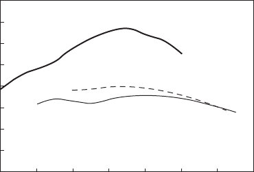
Figure 4.42. Comparison of the specific
torque output between a conventional
four-stroke engine and a two-stroke lean-
burn ‘active radical’ (PDI-AR) engine
[143].
We briefly mention recent further research [143] in the context of the ‘downsizing’
the potential of an HCCI two-stroke engine relative to a comparable, conventional SI
four-stroke engine: This particular example runs closer to stoichiometric. Figure 4.42
shows the specific torque of the PDI-AR (pneumatic DI activated-radical – i.e.
HCCI – engine) in comparison with two other four-stroke engines. The higher specific
torque is a feature of any two-stroke engine: What is remarkable is that HCCI
combustion can be maintained up to about 7000 rpm, which is considerably higher
than has been possible for a four-stroke HCCI engine. The combination of DI and
HCCI combustion means that the usual fuel ‘short circuiting’ is avoided and that NO
x
emissions are low. As is usual with many HCCI engines, UHCs and CO emissions
require an oxidation catalyst. Nevertheless, the fuel economy of this concept, over
the ‘ECE 40’ drive cycle, is 68% better than the original two-stroke engine and 23%
better than the comparable four-stroke.
Four-Stroke HCCI Gasoline Engines
In summary, reference [117] cites four limitations to HCCI operation:
r
poor low-load combustion efficiency,
r
limited high-load ability that is due to limitations of either rapid pressure rise or
high NO
x
emission or misfire,
r
poor understanding of the effect of fuel composition on operating limits and
design criteria,
r
need to control combustion phasing over the load–speed range and through
transients.
Here, we present some results [144] related to the first two points, namely how to
expand the upper and lower boundaries of the HCCI operational range by con-
trolling the compression ignition timing: that depends on, among other variables,
the temperature, pressure, and the fuel concentration of the air–fuel mixture in the
cylinder. As previously mentioned, for gasoline-fuelled engines, it is necessary to
promote ignition, even at a 15:1 compression ratio, through the addition of energy
to the intake charge, and one practical way to do this is by increasing the amount
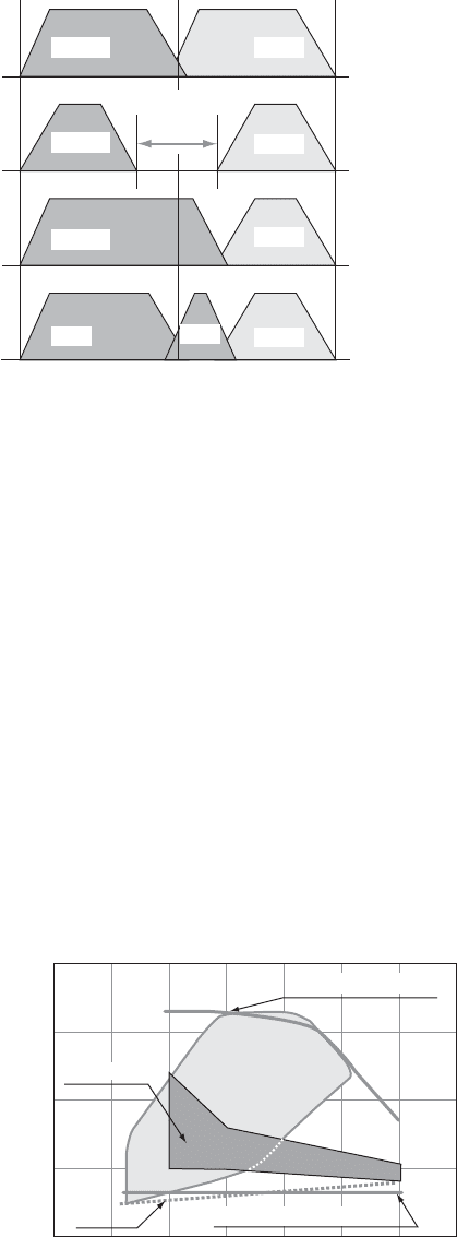
of EGR in the engine. There are several ways in which this can be done by us-
ing variable valve timing, as shown in Fig. 4.43: comparative analysis showed that
4.1 Application of Lean Flames in Internal Combustion Engines 297
IN-1&2EX-1&2
EX-1&2
EX-1&2
EX-1
EX-2
IN-1&2
IN-1&2
IN-1&2
TDC
180 360
Crank angle (deg.)
Exhaust valve
2nd opening
Exhaust valve
late closing
Negative valve
Overlap (NOL)
Conventional
540
NOL=
-deg(CA)
Figure 4.43. Valve timing events for the
control of the amount of EGR using an
electromagnetic valve train for a four-valve
HCCI engine. EX- denotes exhaust valve,
IN- denotes inlet valve [ 144].
negative valve overlap (NOL) was the only method that could achieve HCCI oper-
ation without further external heating of the intake charge. Figure 4.44 shows that
the operational map of the engine with NOL, and PFI is inadequate, at the upper
range, to the demands of the engine load and speed range required for the Japanese
10*15 mode test as well as, at the lower range, the frictional mean effective pressure
of the engine. The upper limit of the operational map was set by the knocking limit,
and the lower was set by the coefficient of variation of the IMEP (‘COV IMEP’).
As previously discussed, these tend to converge with increasing speed. The upper
limit was successfully extended by use of DI, rather than PFI, with a multihole noz-
zle (with performance better overall than that provided by a pintle-type nozzle)
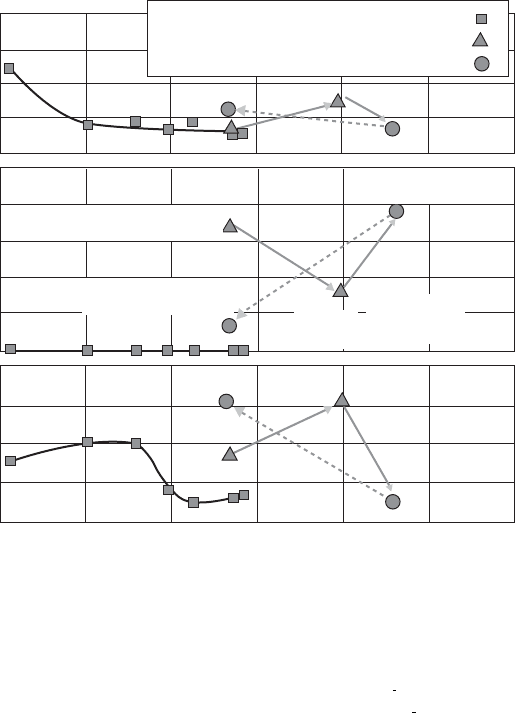
while maintaining excellent fuel economy, Fig. 4.45. This was, however, at the ex-
pense of increased NO
x
emission (Fig. 4.45), suggesting that, as previously discussed,
the premixing is inhomogeneous. Another disadvantage shown in Fig. 4.45 is that
DI in combination with internal EGR results in an increased coefficient of variation
of the IMEP (relative to PFI with external heating of the intake air) because of
cycle-by-cycle variations in the internal EGR temperature and in the generation
800
IMEP(kPa)
0
500
Engine speed (rpm)
1000 2000 3500
200
400
600
1500 2500 3000
Direct injection
10-15mode
N.O.L. Direct Injection
Pmf
ε 15 HCCI
Figure 4.44. Operational range of
HCCI engine with DI during negative
valve overlap (N.O.L.) and compression
ignition, also with DI. The compression
ratio is 15:1. Pmf denotes the frictional
mean effective pressure of the engine.
10–15 mode shows the operational range
required of the engine to cover this drive
cycle [144].
298 Lean Flames in Practice
260
240
220
200
180
10
8
6
4
2
0
8
6
4
2
0
200 300 400
IMEP (kPa)
COV-IMEP(%) ISME NO
x
(g/kWh) ISFC(g/kWh)
500
B
A
C
600 700 800
Ne=1000rpm
CR=15
Tport_air=50°C
Port injection (HCCI)
D.I.(pintle)
D.I.(multihole)
Single θ inj_end=
injection BTDC-5deg
Single θ inj_end=
injection BTDC17deg
Single θ inj_end=
injection BTDC-1deg
Double
injection
θ
inj_end=
BTDC10deg
Di=27%Pi-73%
Figure 4.45. Comparison of fuel consumption (ISFC), emission of indicated specific NO
x
and of the covariance of IMEP as a function of IMEP using various injection strategies:
port injection, DI with a pintle nozzle, and DI using a multihole nozzle [144]. Point A, 4%
internal EGR and DI through multihole injectors (θ
injection end
= BTDC − 5
◦
CA); point B,
20% internal EGR and DI through multihole injectors (θ
injection end
= BTDC − 17
◦
CA); point
C, 30% internal EGR and no DI (HCCI with port fuel injection).
of the air–fuel mixture. The lower load range of HCCI could be extended by the
injection of small amounts of fuel during NOL, although the result was somewhat
marginal.
Further Extension of the Upper Limit: ‘Boosting’ Strategies. That the upper limit of
the operating map of an HCCI engine can be improved by a wide variety of engine
designs and configurations is well known (e.g., the use of a variable compression ratio
[145], spark-assisted operation [146], and supercharging [144]) and research in this
direction continues [147–149]. The question of interest here is the extent to which
the upper limit can be improved by boosting while retaining lean-burn combustion
(note that mechanical superchargers have poor type efficiency: Turbochargers are
more promising but matching is problematic because the exhaust-gas enthalpy is
inevitably low because of the lean operation in HCCI [150]). The work of [151–153]
suggests that this may be possible through the use of pressure waves generated by the
operation of the exhaust valves on a multicylinder engine. Although a description
of the technical details of the operation of t he boosting effect is outside the scope
of this section, it is useful to note that recently it has proven possible to obtain
4.1 Application of Lean Flames in Internal Combustion Engines 299
HCCI (Mid load cam)
HCCI (High load cam –1)
HCCI (High load cam –2)
SI (ε = 11.5)
800
600
400
200
0
10
8
6
4
2
0
10
8
6
4
2
0
0.15
0.10
0.05
0.00
15
10
5
0
50
40
30
20
10
0
400
300
200
100
26
23
20
17
14
*High load cam
–
1data ( ) was not measured.
200
Air–Fuel ratio ISFC (g/kWh) ISCO (g/kWh) ISHC (g/kWh)
ISNO
x
(
g/kWh)[HCCI]
ISNO
x
(
g/kWh) [SI]
COV of IMEP (%)
dP/ d θ max (kPa/deg.)
300 400
Net IMEP kPa
500 600
700
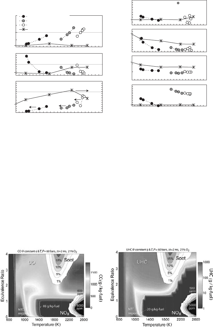
Figure 4.46. Comparison of the performance between HCCI boosted by blowdown super-
charging and SI operation [152].
relatively high IMEP (650-kPa) results with lean-burn combustion (Fig. 4.46) [116].
This was achieved by generating large thermal stratification within the cylinder and
by controlling the mixing between the hot EGR and the intake charge.
Four-Stroke Diesel HCCI; LTC
It is convenient to consider LTC strategies on a Kamimoto–Bae (i.e., temperature
equivalence ratio) map (Fig. 4.47), which shows CO and UHC yields based on
isothermal, isobaric homogeneous reactor simulations, together with two ‘islands’
where NO
x
and soot (particulates) are formed [154]: see [154] for further details and
a brief discussion on the applicability to diesel combustion. If ‘conventional’ diesel
combustion is assumed adiabatic, it starts along a locus with auto-ignition at a φ of
about 4 and goes to completion in a diffusion flame at φ = 1, which unfortunately
Figure 4.47. Left, CO yield at 2.0 ms obtained from a homogeneous reactor simulation of
an n-heptane–air mixture, using the LLNL detailed n-heptane mechanism. The 88-g/kg-fuel
isopleth corresponds to 2% of the fuel energy in CO [154]. Right, UHC yield for the same
conditions as in the figure on the left. (See colour plate.)
300 Lean Flames in Practice
passes through the two islands [117] and leads to the well-known undesirable emis-
sion characteristics of the diesel engine. To avoid this intersection, measures that
lower the flame temperature (such as lowering the compression ratio and mixing
the fresh charge with EGR and enhancing precombustion mixing) and that make
the equivalence ratio leaner (such as advancing the injection timing during the com-
pression stroke, raising the injection pressure, reducing the nozzle orifice size, and
increasing the swirl) are desirable. These strategies result in cooler and leaner flames
than conventional CI combustion, giving rise to the LTC nomenclature, with some,
but not all, of the fuel being burnt at an equivalence ratio that is lean of stoichiometric
and the remainder of the charge usually extending to richer than stoichiometric. LTC
is thus a hybrid between lean HCCI and conventional non-premixed CI, which aims
to keep emissions of particulates and NO
x
low while retaining the control of com-
bustion phasing through the timing of the (main) injection pulse, as in conventional
diesel combustion.
The strategies for LTC operation with diesel fuel can be classified [117] as one of
two kinds: either injection at approximately TDC or very advanced injection. The aim
(for both approaches) is to allow sufficient time for mixing between the fuel vapour
and the air before ignition (which implies that it is usually desirable to complete
injection before ignition). We begin by describing the strategies and conclude this
subsection with a review of the evidence for the extent of lean combustion.
The approach involving injection about TDC retains a closer coupling between
the injection and the combustion events and therefore retains the hope of closer
control of the phasing of ignition; but this also limits the time available to promote
mixing. This approach makes use of largely ‘conventional’ injection equipment and
cylinder bowl geometry and is sometimes known as ‘modulated kinetics’ (MK) [103].
Injection is retarded to ATDC, which provides some time for the mixing by delaying
the auto-ignition that is due to the expansion – and hence reducing the temperature
and density of the gases in the power stroke – and introducing large amounts of
EGR, to lower the temperature and to reduce the oxygen concentration and further
delay auto-ignition. Note that, as pointed out in [155], the increase in ignition delay
that is due to EGR is offset by the lower in-cylinder ambient concentrations of
oxygen, so that the equivalence ratios at ignition are likely to be unchanged by the
addition of EGR. The retarding may lead to a reduction in the cycle efficiency but
with the introduction of swirl, heat transfer losses are reduced and cycle efficiency
is maintained [103]. The extension to higher loads involves overcoming shortened
ignition delay times and the need to inject a larger quantity of fuel. These objectives
can be achieved, respectively, by further reduction of the gas temperature field, by
either cooling the EGR or reducing the compression ratio (or both) and by the
use of a high-pressure common-rail injection system. The optimised system leads to
a simultaneous reduction in NO
x
and particulates. However, as reported in [117],
levels of CO and HC emissions can be high under certain conditions, and these were
recently measured by planar induced fluorescence techniques [154].
The approach involving very advanced injection was achieved [156], although
the conclusion, as for gasoline-fuelled HCCI, is that HCCI diesel is appropriate
up to medium loads, beyond which the rate of pressure rise is too abrupt and that
the control of all the variables that can affect HCCI–diesel auto-ignition presents
a considerable challenge [117]. It clearly allows greater time for some evaporation
4.1 Application of Lean Flames in Internal Combustion Engines 301
before ignition: However, it is now necessary to ensure adequate mixing and to avoid
fuel impinging onto the cylinder wall. This led to the development of the design of
a narrow-angle direct-injector concept [157] with an appropriate (“omega”) piston
bowl s hape that was optimised for both low and medium loads, together with EGR to
control the ignition delay, and able to switch the mode at high loads to conventional
diesel combustion. An alternative way in which to reduce the spray penetration at
low in-cylinder densities is to use multiple injections [104].
The control of the ignition timing is determined by the – necessarily relatively
long – ignition delay: To avoid complete reliance on the inevitably delicate control
of the ignition time through the low-temperature chemistry of the mixture, a hybrid,
dual-injection scheme, known as UNIBUS [158], was developed, which involves ad-
vanced injection (−50
◦
ATDC) of a portion of the fuel followed by the remainder
being injected, as in conventional CI designs, around TDC to act as a trigger for the
ignition, and subsequent combustion, of the whole charge. Thus, the argument runs,
much of the fuel is burnt in a lean environment, avoiding soot formation. As with the
approach of the preceding paragraph, large amounts of EGR are introduced to di-
lute the combustion gases, thereby reducing flame temperatures. Experiments [159]
have now led to a conceptual model for this scheme – at least for the case of an opti-
cally accessed heavy-duty engine (i.e., 139.7-mm bore, 97.8-mm bowl width operated
with an equivalent of 60% EGR and operation at the threshold of soot formation).
Comparable measurements for MK-like combustion were also presented in [160],
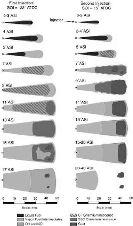
but no conceptual model has yet been presented. Figure 4.48 shows the UNIBUS
conceptual model, which differs significantly from the corresponding model of con-
ventional diesel combustion [161] shown in Fig. 4.49. During the first injection, the
liquid phase has disappeared by about 5
◦
ASOI (after the start of injection) and a
cool flame (identified by chemiluminescence) is present throughout the length of
the jet: This is not observed in conventional diesel combustion. High-temperature
second-stage ignition reactions start downstream at 13
◦
ASOI, and broad distribu-
tions of OH radicals start to appear in the same region by 15
◦
ASOI, indicating a
mixture that is leaner and more uniform than for conventional diesel combustion.
In the latter, OH is formed in a thin ribbon-like region around the periphery of the
jet. Isolated islands of soot arise, near the edge of the bowl, which is mostly oxidised
by 22
◦
ASOI. These thus, presumably, identify fuel-rich regions – implying that most
of the jet is therefore below sooting limits: For conventional diesel combustion, the
mixture in the interior of the jet is quite rich (φ>2), leading to soot formation
throughout the jet cross section. The reactions accompanying the second injection
are closer to conventional diesel combustion: Cool flames (again identified by chemi-
luminescence) begin by 5
◦
ASOI rapidly followed by the appearance of second-stage
ignition and a putative non-premixed flame may arise on the perimeter of the jet.
By 9
◦
ASOI, soot is being produced more or less throughout the downstream region
of the jet: The upstream part seems to be devoid of reaction until about 20
◦
ASOI.
After this time, soot remains downstream and weak broadband fluorescence, per-
haps either ‘from unburned fuel or other combustion intermediates’, remains near
the injector long after the end of combustion. This suggests that this region may be
the origin of the HC emissions observed with LTC.
The essential determinant for the existence of lean-burn combustion is ‘posi-
tive ignition dwell’, that is, ignition starts after the end of injection [155]. This, in
302 Lean Flames in Practice
Figure 4.48. Schematic representation of
the spray, combustion and emissions pro-
cesses for the low-temperature, double-
injection (UNIBUS-like) condition (first
injection in left column and second injec-
tion in right column) [159]. SOI is start
of injection, ASI is after start of injection
(See colour plate.)
turn, arises at low load when the fuel jet does not establish a quasi-steady period.
In experiments similar to those previously described [162], images show that igni-
tion chemiluminescence begins between 20 and 40 mm downstream of the nozzle
with the existence of formaldehyde during first-stage ignition: Related equivalence
ratio measurements extend from fuel lean to fuel rich. Furthermore, in [155]itis
suggested that the subsequent presence of significant OH throughout the jet’s cross
section implies that much of the downstream jet must have φ in the neighbourhood
of unity. Further evidence for this comes from the measurement of the equivalence
ratio after the end of injection, and thus relevant to the conditions considered here,
by Rayleigh scattering [163]. The conditions are broadly comparable but were mea-
sured in a constant-volume chamber. The measurements show that much of the
jet 30 mm downstream of the injector is near φ = 1 with mixtures leaner than that
closer to the injector. Finally, in [164], formaldehyde was measured by PLIF, and it
was found that it formed strongly and remained in the upstream region of the jet.
An associated chemical kinetic simulation suggests that formaldehyde would indeed
persist if mixtures were too lean for complete combustion, say φ<0.5.
