Sundararaja D. The Discrete Fourier Transform. Theory, Algorithms and Applications
Подождите немного. Документ загружается.

244
Aliasing and Other Effects
Reduction of leakage
To reduce leakage, the natural solution is to use an appropriate record
length, if possible. Similar to the case of the aliasing problem, prior knowl-
edge of a signal will enable to fix the record length or a trial and error
procedure can be used, keeping the sampling interval fixed. Otherwise,
leakage can be reduced at the expense of increased smearing of the spec-
trum by the application of windows. As mentioned earlier, if there is no
leakage or negligible leakage then choose the rectangular window. Other-
wise choose any of the other windows that reduces the side lobes to the
desired level. Windows can be applied in the time-domain by multiplying
the data, x(n), with window samples, w(n). That is, instead of comput-
ing the DFT of x(n), we compute the DFT of x(n)w(n). Note that the
window w(n) must be centered on the truncated signal x{n) in the defined
interval of x(n), wherever it may be on the time scale. Windows can also
be applied, in the frequency-domain, in terms of the frequency coefficients
of the rectangular window. Although our discussion concentrated on the
truncation problem in the time-domain, it should be noted that windows
can be used in both the time- and frequency-domains.
11.3 Picket-Fence Effect
In this section, we consider the appropriate frequency spacing or increment
for the unique representation of a signal. The theory of Fourier analysis is
that the frequency increment between the harmonic components must be
the reciprocal of the period of the waveform under analysis. Here again, we
run into a problem because we tend to violate the theory by not provid-
ing proper frequency spacing (because of not using a long enough record
length), in order to make the problem suitable for numerical analysis.
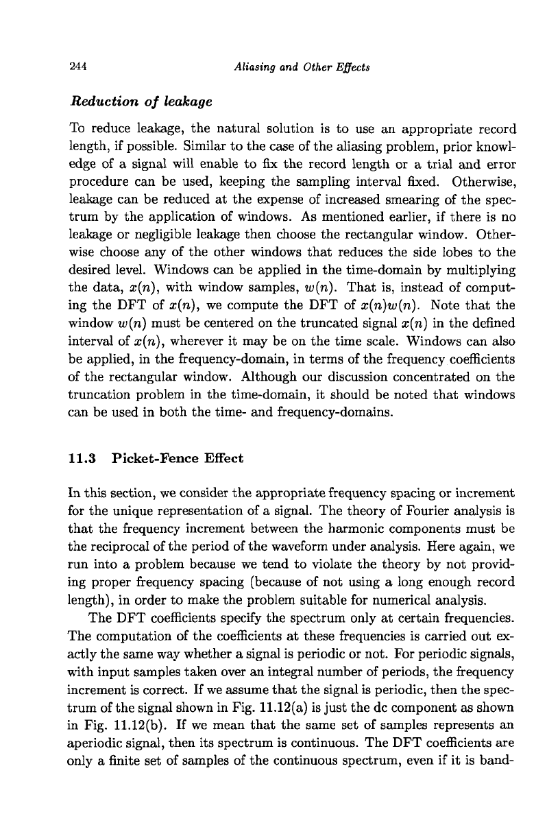
The DFT coefficients specify the spectrum only at certain frequencies.
The computation of the coefficients at these frequencies is carried out ex-
actly the same way whether a signal is periodic or not. For periodic signals,
with input samples taken over an integral number of periods, the frequency
increment is correct. If we assume that the signal is periodic, then the spec-
trum of the signal shown in Fig. 11.12(a) is just the dc component as shown
in Fig. 11.12(b). If we mean that the same set of samples represents an
aperiodic signal, then its spectrum is continuous. The DFT coefficients are
only a finite set of samples of the continuous spectrum, even if it is band-
Picket-Fence Effect
245
16 i
=
1
* 0
.
0
_ 1
e
K
0
0
_ 1
e
0
16
5
N=16
n
(a)
W = 32
16
n
(c)
N
=
64
32
n
<•)
10
48
15
31
63
3f
5
*
}
0
.
0
16 *
0
•
•
0
16 *
•
0
• •
2
5
10
• •
4
k
(b)
10
k
(d)
20
k
(0
•
6
_j
8
. • .
15
30
Fig. 11.12 (a) A signal and (b) its spectrum, (c) The signal shown in (a) with 16 zeros
appended and (d) its spectrum, (e) The signal shown in (a) with 48 zeros appended and
(f) its spectrum. With more and more zero padding, a denser spectrum is obtained.
limited. Therefore, the spectrum shown in Fig. 11.12(b) is also the correct
frequency-domain representation of the aperiodic signal, but is very coarse.
It seems as though we look at the spectrum through a picket-fence. With
a coarse spectrum, we may miss some of its features. For example, if there
is a peak of the spectrum in between two frequencies it will be missed.
How to make the spectrum denser
As the frequency spacing is inversely proportional to the record length of the
time-domain signal, we get a coarse spectrum with a short record length.
Only by increasing the input record length, we can have a denser spectrum.
The best thing to do is to reduce the level of truncation, if employed, and
get samples over a longer record length. If the nonzero part of the record
of a signal is finite, then pad the signal with zeros at the end to make
the record length longer. If required, a window should first be employed
and then zero padding carried out. Figure 11.12(c) shows the signal in
Fig. 11.12(a) padded with 16 zeros. The corresponding spectrum, shown
in Fig. 11.12(d), presents a denser spectrum (only half of the spectrum is
246
Aliasing and Other Effects
shown since it is symmetric). With more and more zero padding, we get a
denser spectrum as shown in Figs. 11.12(e) and (f). The signal shown in
Fig. 11.12(e) is a more accurate representation of the given aperiodic signal
than that shown in Fig. 11.12(c).
A periodic signal is composed of components with frequencies which are
integral multiples of its frequency and of no other. Therefore, we should set
the record length equal to an integral number of cycles and there should be
no zero padding. If
we
truncate a periodic signal, we are making an analysis
with a false period. An aperiodic signal is composed of components of all
frequencies. Whether we truncate an aperiodic signal or not, the frequency
coefficients computed by DFT are part of the spectrum. The point is that
the signal processed by the DFT should be sufficiently close to the actual
signal, with the appropriate selection of the record length and the number
of samples so that the aliasing and leakage errors are small enough and the
spectrum is sufficiently denser.
11.4 Summary and Discussion
• In this chapter, we studied the aliasing, leakage, and picket-fence
effects. These effects occur, in the analysis of a signal, due to the
setting of parameters such as record length, sampling interval, and
frequency spacing not in accordance with the theory of the Fourier
analysis, in order to use the DFT. It is normal that the DFT solu-
tion is not exact as the solution given by analytical method. But,
the analytical method is almost impossible to use with practical
signals. What is important is to ensure that the error in DFT rep-
resentation is within the required limits. Fortunately, we can reduce
the errors to any desired level by increasing the number of samples
and/or the record length and using other techniques presented.
• Noting that DFT means the same computation at any time, the
accuracy control lies in the data modeling. Although sampling and
truncation are unavoidable to analyze a signal using the DFT, the
user has to ensure that the digital signal is sufficiently close to the
actual signal to keep the errors within tolerable limits. Therefore,
if the DFT of a signal seems to be in gross error it is because of im-
proper data modeling, such as insufficient sampling rate, too much
of truncation, insufficient number of bits to represent data values,
Exercises
247
etc.
The situation is like using a computer to solve a problem. A
computer executes some instructions in a predefined way. If the
execution of a program yields improper output, the reason is either
the programmer not putting up the proper algorithm, or proper
codes according to the language used, or proper input data.
• In the next two chapters, we describe the approximation of the
continuous-time Fourier series and Fourier transform of signals and
provide examples illustrating the effects described in this chapter.
Reference
(1) Brigham, E. O. (1988) The Fast Fourier Transform and Its Appli-
cations, Prentice-Hall, New Jersey.
Exercises
11.1 What is the minimum number of samples in a period required to avoid
aliasing. What are the DFT coefficients. Find the DFT coefficients with 4,
8, 16, and 32 samples in a period.
(a) x(t) = -4sin(107ri)
(b) x(t) = cos(107ri)
* (c)x(t) = 2cos(147rt)
(d) x(t) = 5sin(167rt)
(e) x(t) =3cos(327it)
(f) x(t) =4sin(127rt)
(g) x(t) =2cos(24?ri)
(h) x(t) = -3
11.2 With JV = 8 and L = 8, list the DFT coefficients of the signal using
the rectangular, triangular, Hann, and hamming windows.
(a) x(n) = cos(^2n)
* (b) x(n) = cos(^2.5n)
* 11.3 The frequency of the significant highest possible frequency com-
ponent of an aperiodic signal of record length 0.1 seconds is 5 kHz. A
minimum frequency increment of 20 Hz is required. Determine the number
of samples required to approximate the spectrum using the DFT. Is zero
248
Aliasing and Other Effects
padding required? If so, what is the minimum record length required?
11.4 The frequency of the significant highest possible frequency component
of an aperiodic signal of record length 0.1 seconds is 12.5 kHz. A minimum
frequency increment of 5 Hz is required. Determine the number of sam-
ples required to approximate the spectrum using the DFT. Is zero padding
required? If so, what is the minimum record length required?
Programming Exercises
11.1 Write a program to apply the Hann window to a signal, with L = JV'.
11.2 Write a program to apply the hamming window to a signal, with
L = N.
11.3 Write a program to apply the triangular window to a signal, with
L = N.
Chapter 12
The Continuous-Time Fourier Series
The FS is the frequency-domain representation of a continuous-time peri-
odic signal in terms of an infinite set of harmonically related sinusoids in
addition to a dc value. Both the DFT and the FS do the same function,
that is, providing the sinusoidal representation of signals. However, the
DFT analyzes a discrete signal whereas the FS analyzes a continuous-time
signal. Therefore, the essential differences to be considered in approximat-
ing the FS coefficients by those of the DFT are: (i) the integral evaluated
in the case of the FS is approximated by a numerical integration procedure
and (ii) a finite set of coefficients is used in DFT and an infinite set of
coefficients is used in FS.
In Sec. 12.1, we start with the two forms of the definitions of the 1-D FS,
describe the Gibbs phenomenon, present the relation between the DFT and
the FS, and conclude with an example of approximating the FS coefficients
by those of the DFT. In Sec. 12.2, we describe the approximation of the
2-D FS coefficients by those of the DFT.
12.1 The 1-D Continuous-Time Fourier Series
The FS represents a continuous-time periodic signal, x(t), with period T
as a sum of an infinite set of harmonically related sinusoids in addition
to a dc value. The frequency of the fundamental harmonic is
u>o
= ^.
The frequencies of the other harmonics are integral multiples of w
0
. The
sufficient conditions, called Dirichlet conditions, a signal should satisfy so
that it can be represented by a Fourier series are: (i) the signal x(t) has an
absolutely convergent integral, that is /
0
|x(t)|di < oo, (ii) the signal has
249
250
The Continuous- Time Fourier Series
a finite number of maxima and minima in one period, and (iii) the signal
has a finite number of finite discontinuities in one period. These conditions
are met by most signals of practical interest.
The trigonometric form
A real periodic signal, x(t), satisfying Dirichlet conditions, can be equiva-
lently expressed in terms of cosine and sine waveforms as
oo
x(t) = X
c
(0) +
Y^(X
c
(k)
cos(k(j
0
t) + X
a
(k) sm(kuj
0
t)), (12.1)
where
1 /Tl-t-i
Xc(0) =
T
J x(f)dt,
o rti+T
X
c
(k)
= — I x(t) cos(fcw
0
*) dt, k =
1,2,...,
T Jti
ti+T
{']
'" . ~ ", ' ~.~. ,oo
tl
2
f
tl+T
X„(k) = — x(t) sm(kcj
0
t) dt, k=l,2,...,oo
1
Jh
and ti is arbitrary.
The exponential form
As in the case of the DFT, it is more efficient to represent a sinusoid in
terms of complex exponentials. Substituting the fact that
e
jk<jj
0
t i
e
—jkwot
e
Jkuiot _
e
—jku>ot
cos(ku>ot)
— and sin(kuiot) =
into Eq. (12.1), we get
00
p
jkuot _i_
p—jkuiot
pjkuot _
p
—jkuot
x(t) = X
c
(0) + ]T(X
e
(fc)- \ + *.(*) a )
fc=i
J
Rearranging the terms, we get
*(*)
=
XM
+
fv^W-^W
+
x
c(k)
+j
x
8
(k)
e
_
jkuot)
k=l
The 1-D Continuous-Time Fourier Series 251
Let
X
C8
(0)
=
X
e
(0),
X
C8
(k)
= *°W-/M*>, and
X
cs
(-k)
= *°W+J'*-W.
Note that X
cg
(fc) and X
cg
(—fc) are complex conjugates, and X
c
{k) =
2Re(X
c8
(k)) and X
8
(k) = -21m(X
cs
(k)). Now, x(t) can be expressed
as
oo
x(t) =
X
C8
(0)
+ £(X
C8
(A;)e
w
+ X„ (-*)e-'
fa
*>«)
By allowing the summation index, k, to run from — oo to oo, we can rewrite
the equation as
oo
x(t) = J2
X
cs(k)e
j
^
ot
(12.2)
fc= — oo
We use the denning equations for X
c
(k) and X
8
(k) to get
X
C8
(k)
as
1 /-
tl+T
x
cs(k) = = / 2;(i)(cos(fcw
0
i) - jsin(fcw
0
i))^,
1 /"'
1+T
= - / x{t)e-
jkuot
dt, k = -oo,...,
-1,0,1,...,
oo (12.3)
Gibbs phenomenon
The failure of the Fourier representation to provide uniform convergence in
the vicinity of a discontinuity of a signal is called the Gibbs phenomenon.
In the vicinity of a discontinuity, the Fourier representation deviates at the
least about 9% from the original signal irrespective of the number of coeffi-
cients used. It is not surprising since it is impossible to provide a pointwise
match in the vicinity of a discontinuity with a set of basis functions each
of those is continuous. Where there is no discontinuity, by increasing the
number of frequency coefficients to represent a signal, the Fourier represen-
tation can be made to correspond to the original signal to any tolerance.
Let us assume that we are approximating a signal using only part of its
spectrum (2JV+1 complex frequency coefficients). The part of the spectrum
used can be considered as obtained by multiplying the original spectrum by
a rectangular window whose value is unity during the part of the spectrum
used and zero otherwise. This multiplication operation in the frequency-
domain is equivalent to convolution of the corresponding signals in the
time-domain. Now, we are going to derive the convolution expression that
252
The Continuous-Time Fourier Series
will help us to understand the characteristics of the reconstructed signal.
The FS synthesis expression with 2iV + 1 coefficients is given by
N
k=-N
Replacing
X
cs
(k)
by its definition and interchanging the order of summation
and integration, we get
N
*N(t)
= i f x(l) J2 e
jk
»°Wdl
1 Jo
k=-N
Let us evaluate the summation operation separately.
N
y^
e
jkuj
0
{t-i)
k=-N
2N
y^
e
j(k-N)w
0
(t-i)
k=0
l_
e
i(2iV+l)wo(t-0
_
e
-jNw
Q
{t-l)_
sin(
(2N+l)u
0
{t-l)
)
I
—
e
Juo(t-l)
sin(^i)
Now, the convolution expression characterizing the reconstructed signal
using only 2N + 1 coefficients is given by
XN
(t) =
±j\(l)
sin(
(2Af+iHft-i?
)
8i
n(i-2^1)
i r
T
= - / x(l)xs(t - l)dl
1
Jo
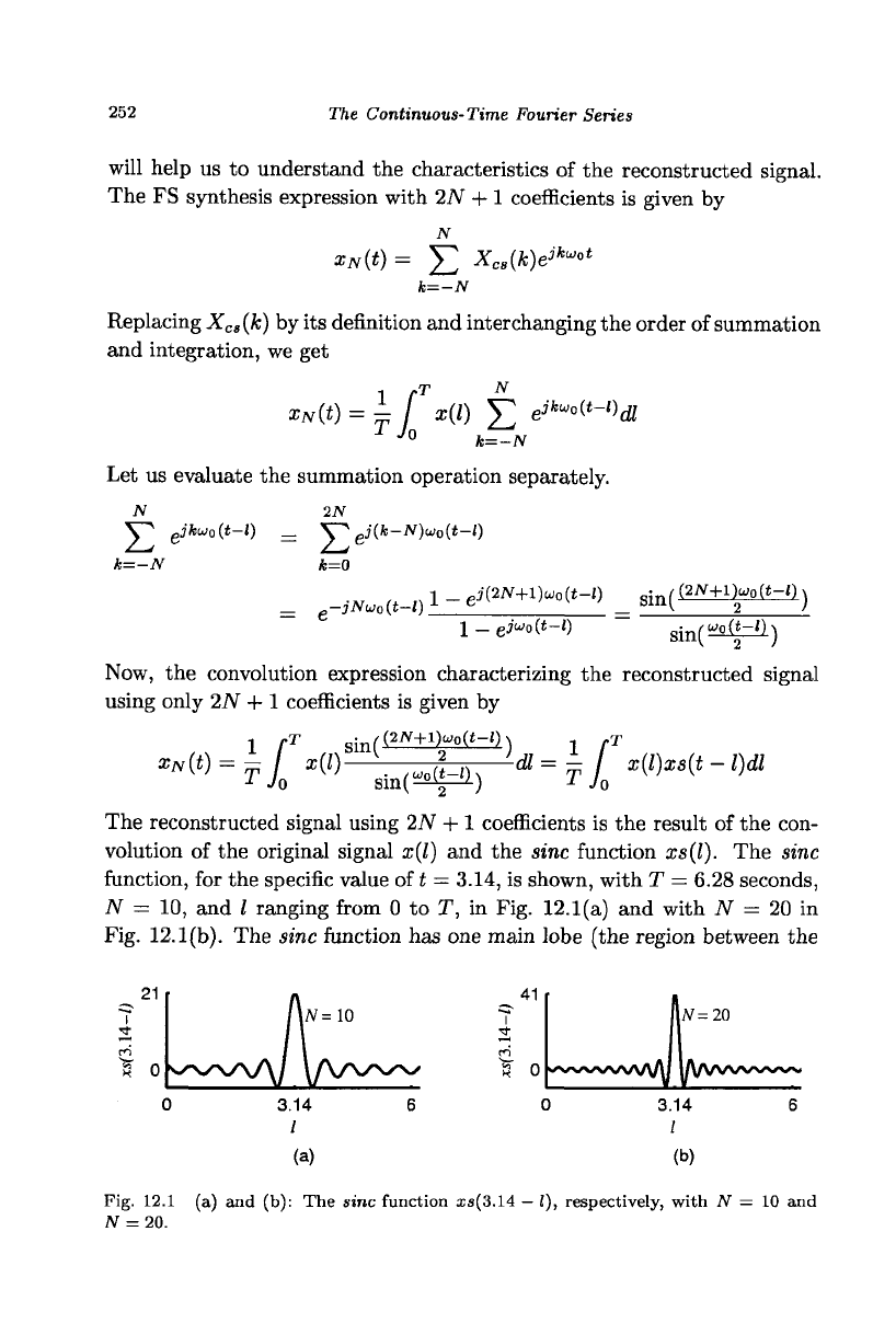
The reconstructed signal using 27V + 1 coefficients is the result of the con-
volution of the original signal x(l) and the sine function
xs(l).
The sine
function, for the specific value of t = 3.14, is shown, with T = 6.28 seconds,
N = 10, and I ranging from 0 to T, in Fig. 12.1(a) and with N = 20 in
Fig. 12.1(b). The sine function has one main lobe (the region between the
(a)
(b)
Fig. 12.1 (a) and (b): The sine function is(3.14
—
I), respectively, with N = 10 and
AT
= 20.
The 1-D Continuous-Time Fourier Series
253
(a)
(b)
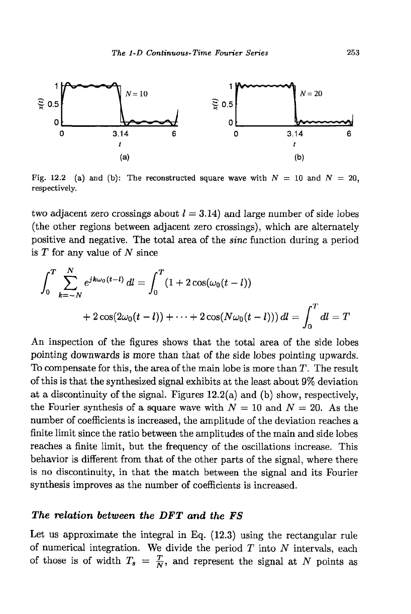
Fig. 12.2
(a) and
(b): The reconstructed square wave with JV
= 10
and JV
= 20,
respectively.
two adjacent zero crossings about
/ =
3.14) and large number of side lobes
(the other regions between adjacent zero crossings), which are alternately
positive and negative. The total area of the sine function during
a
period
is
T
for any value of JV since
f
Y"
gifc-oC*-*)
a
=
f (l + 2cos(wo(t-0)
J
°
k=-N
J
0
+
2
cos(2cj
0
(t
-
I)) +
• • •
+
2
cos(Noj
0
(t
-
I))) dl
= /
dl =
T
Jo
An inspection
of
the figures shows that the total area
of
the side lobes
pointing downwards is more than that of the side lobes pointing upwards.
To compensate for this, the area of the main lobe is more than T. The result
of this is that the synthesized signal exhibits at the least about 9% deviation
at
a
discontinuity of the signal. Figures 12.2(a) and (b) show, respectively,
the Fourier synthesis of
a
square wave with
N =
10 and JV
=
20. As the
number of coefficients is increased, the amplitude of the deviation reaches
a
finite limit since the ratio between the amplitudes of the main and side lobes
reaches
a
finite limit, but the frequency of the oscillations increase. This
behavior is different from that of the other parts of the signal, where there
is no discontinuity,
in
that the match between the signal and its Fourier
synthesis improves as the number of coefficients is increased.
The relation between
the
DFT and the
FS
Let
us
approximate the integral
in
Eq. (12.3) using the rectangular rule
of numerical integration. We divide the period
T
into JV intervals, each
of those
is of
width
T
s
= ^,
and represent the signal
at
JV points
as