Sundararaja D. The Discrete Fourier Transform. Theory, Algorithms and Applications
Подождите немного. Документ загружается.

94
Properties of the DFT
4.14 Find the circular convolution of the frequency-domain sequences,
X(k) = {2+jl,l-j4,2+j5,3+j2}and#(fc) = {2+j3,l-j2, l-jl,2+j4}
using the DFT.
4.15 Find the circular cross-correlation of the time-domain sequences, x{n)
and h(n), using the DFT. Deduce the correlation of h(n) and x(n).
* 4.15.1 x(n) = {3,4, -1,2} and h(n) = {3,
-1,3,4}.
4.15.2z(n) = {2 + jl,l-j4,2 + j5,3+j2}and/i(7i) = {2 + j3,l-j2,l-
jl,2 + j4}.
4.16 Find the circular autocorrelation of the time-domain sequence using
the DFT.
4.16.1 x(n) =
{2,4,-1,2}.
4.16.2 x(n) = {j2,
j4,-jl,j2}.
4.16.3 x{n) = {2 + jl,
1
- j4,2 + j5,3 + j2}.
4.17 Find X(0) and X(4) with x(n) = {2 + jl, 1 - j4,2 + j5,3 + j2,3 -
j2,2-jl,l-j3,2+j2}.
4.18 Find x(0) and x(4) with X(k) = {2 - jl, 4 + j4,2 - j5,3 - j2,3 -
jl,2
+
jl,l-j3,2-j2}.
4.19 Let x(n) = {2 + jl,4 - j4,1 - j'5,3 - j2}. Compute X(k). Deduce
y(0),
Y(2), F(4), and F(6) from X{k) if j/(n) = {2 + jl,4- j4,l - j5,3-
j2,0,0,0,0}.
4.20LetX(ifc) = {2-jl,3-j4,l-;'5,3-j2}. Compute x{n). Deduce y(0),
y(2),
2/(4), and 2/(6) from x(n) if Y{k) = {2-
j'1,3-
j4,l - j5,0,0,0,0,3-
J2}.
4.21 Let x{n) = {2 + jl,4 - jl, 1 - j2,3 - j2}. Compute X(k). Deduce
y(fc)fromX(fc)if2/(n) = {2 + jl,0,4-jl,0,l-j2,0,3-j2,0}.
4.22 Let X(k) = {1 - jl, 2 - j4,1 - j5,3 + j2}. Compute x{n). Deduce
y(n) from x(n) if Y(k) = {1 - jl, 0,2 - j4,0,1 - j5,0,3 +
j2,0}.
4.23 Verify ParsevaFs relation.
* 4.23.1 x{n) = {1 - j3,1 + j4,1 - j2,3 - j2}.
4.23.2 x(n) = {1 - j3,1 + j4,1 - j2,3 - j2} and h(n) = {1 + j3,1 + jl,3 -
Ai-J'2}-
Chapter 5
Fundamentals of the PM DFT
Algorithms
If we compute the DFT or IDFT from definition, the computational com-
plexity is 0(N
2
) and they will not be efficient for signal analysis. Therefore,
the task now is to develop fast algorithms for these operations. Due to the
similarity of the DFT and the IDFT computation, a DFT algorithm can
be used to compute the IDFT with trivial modifications. Therefore, we
concentrate on the development of DFT algorithms.
The computation required for an TV—point DFT is the evaluation of N
sums,
each of N products. The data values are the same and a set of
TV
twiddle factors is repeatedly used in forming the products for computing
each of the N sums. Therefore, there is a large amount of redundancy in the
computation. For example, with N = 8, the data sample x(l) is multiplied
by Wg and — W$ in order to compute the coefficients X(l) and X(5),
respectively. We can use any method to find the sum of products, but the
object is to reduce the number of multiplication and addition operations.
Typically, a multiplication operation is split and is carried out in stages. For
example, a multiplication by W^ is split into multiplications by W^ and
Wtf. This approach helps the usage of partial results for the computation
of more than one coefficient. A multiplication is carried out after adding
all possible terms. Now, the way to split the multiplications and share the
partial results is found using the DFT properties.
An alternate view of the problem of the computation of the DFT is
that a larger DFT is decomposed into a large number of smaller DFTs, in
particular into two-point DFTs, and the coefficients of the smaller DFTs
are combined to form the coefficients of the larger DFT. Again, the DFT
properties are used to find the procedure of decomposition and combina-
95
96
Fundamentals of the PM DFT Algorithms
tion. In short, the classical divide-and-conquer strategy of developing fast
algorithms is used.
In Sec. 5.1, first, we reformulate the DFT definition using vector input
and output quantities with each vector having two complex values. Then,
the reformulation is extended to any vector length. In Sec. 5.2, the direct
implementation of the reformulated DFT definition is described. In Sec. 5.3,
the reformulation of the IDFT definition in terms of vector quantities is
presented. The computation of the IDFT using DFT is described in Sec. 5.4.
In Sees. 5.5 and 5.6, the PM DIT DFT and the PM DIF DFT type of
algorithms, respectively, are developed for N = 8. In Sec. 5.7, the set of
PM DFT algorithms is classified.
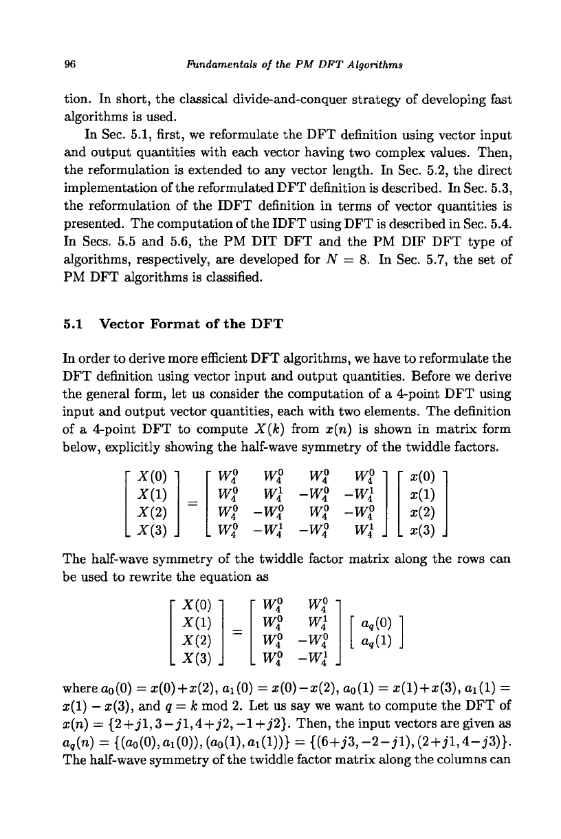
5.1 Vector Format of the DFT
In order to derive more efficient DFT algorithms, we have to reformulate the
DFT definition using vector input and output quantities. Before we derive
the general form, let us consider the computation of a 4-point DFT using
input and output vector quantities, each with two elements. The definition
of a 4-point DFT to compute X(k) from x(n) is shown in matrix form
below, explicitly showing the half-wave symmetry of the twiddle factors.
*(0)1
X(l)
X{2)
X{2)\
• w
4
°
W
4
°
wl
. w2
w%
wl
-w%
-wl
w%
-w$
w2
-w%
w2
'
-wl
-w%
wl
.
r
x(o)
x(l)
x(2)
1.3(3)
The half-wave symmetry of the twiddle factor matrix along the rows can
be used to rewrite the equation as
X(0)1
X(l)
X(2)
X(3)
J
r
W2
w2
w2
w2
w° •
wl
-w2
-wl .
• a,(0) "
. a,(l) .
where a
0
(0) = x(0)+x{2), ai(0) = x(0)-x(2), a
0
(l) = a?(l) +
a;(3),
ai(l) =
a;(l)
—
x(3), and q = k mod 2. Let us say we want to compute the DFT of
x(n) = {2+jl,3—jl,4+j'2,
—1+J2}.
Then, the input vectors are given as
a
g
(n) = {(a
0
(0),
ai
(0)),(ao(l),ax(l))} = {(6+A-2-jl),(2+iM-j3)}.
The half-wave symmetry of the twiddle factor matrix along the columns can
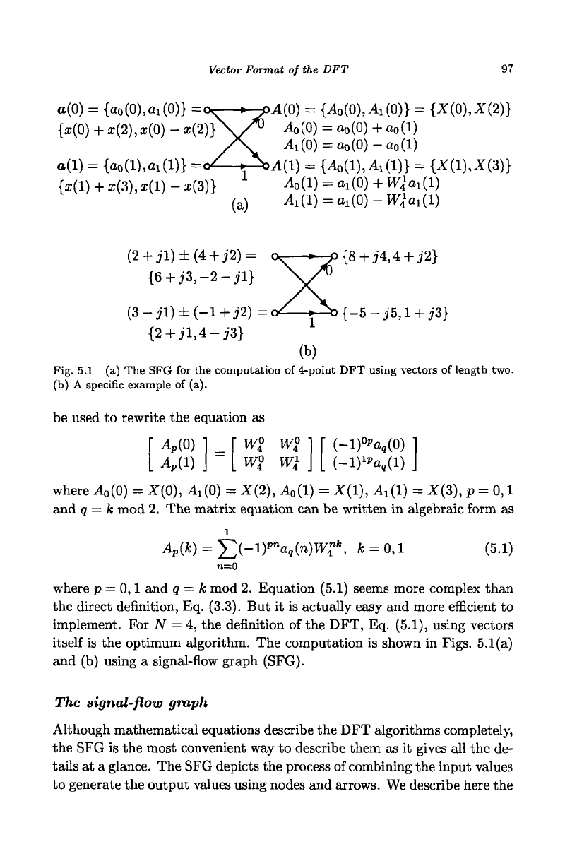
Vector Format of the DFT
97
o(0) = {o
0
(0),o
1
(0)} =
{s(0) + x(2),a;(0)-x(2)}
o(l) = {o
0
(l),o
1
(l)} =
{x(l) + x(3),x(l)-x(3)}
(a)
A(0) = {Ao{0)MO)} = {X(0),X(2)}
Ao(0) = a
o
(0)+a
o
(l)
A
1
(0) = a
o
(0)-a
o
(l)
il(l) =
{^,(l),A
1
(l)}
= {X(l),X(3)}
i4
0
(l) = ai(0) + W
4
1
ai(l)
Ai(l) = ai(0)-W
4
1
ai(l)
(2 + jl)±(4 + j2) =
{6 + j3,-2-jl}
(3-jl)±(-l+j2) =
{2+jl,4-j3}
{8 + j4,4 + j2}
^b{-5-j5,l + j3}
(b)
Fig. 5.1 (a) The SFG for the computation of 4-point DFT using vectors of length two.
(b) A specific example of (a).
be used to rewrite the equation as
P
(0)
A
P
(1)
w2
(-l)
0p
a,(0)
L
(-l)
lp
a
g
(l) J
where A
o
(0) = X(0), A^O) = X{2), A
0
{l)=X(l), Ai(l) = X(3), p = 0,1
and q
—
k mod 2. The matrix equation can be written in algebraic form as
MQ = £(-i)
pn
a»wT*,
*
= o,i
(5.1)
n=0
where p = 0,1 and 9 = k mod 2. Equation (5.1) seems more complex than
the direct definition, Eq. (3.3). But it is actually easy and more efficient to
implement. For JV = 4, the definition of the DFT, Eq. (5.1), using vectors
itself is the optimum algorithm. The computation is shown in Figs. 5.1(a)
and (b) using a signal-flow graph (SFG).
The signal-flow graph
Although mathematical equations describe the DFT algorithms completely,
the SFG is the most convenient way to describe them as it gives all the de-
tails at a glance. The SFG depicts the process of combining the input values
to generate the output values using nodes and arrows. We describe here the
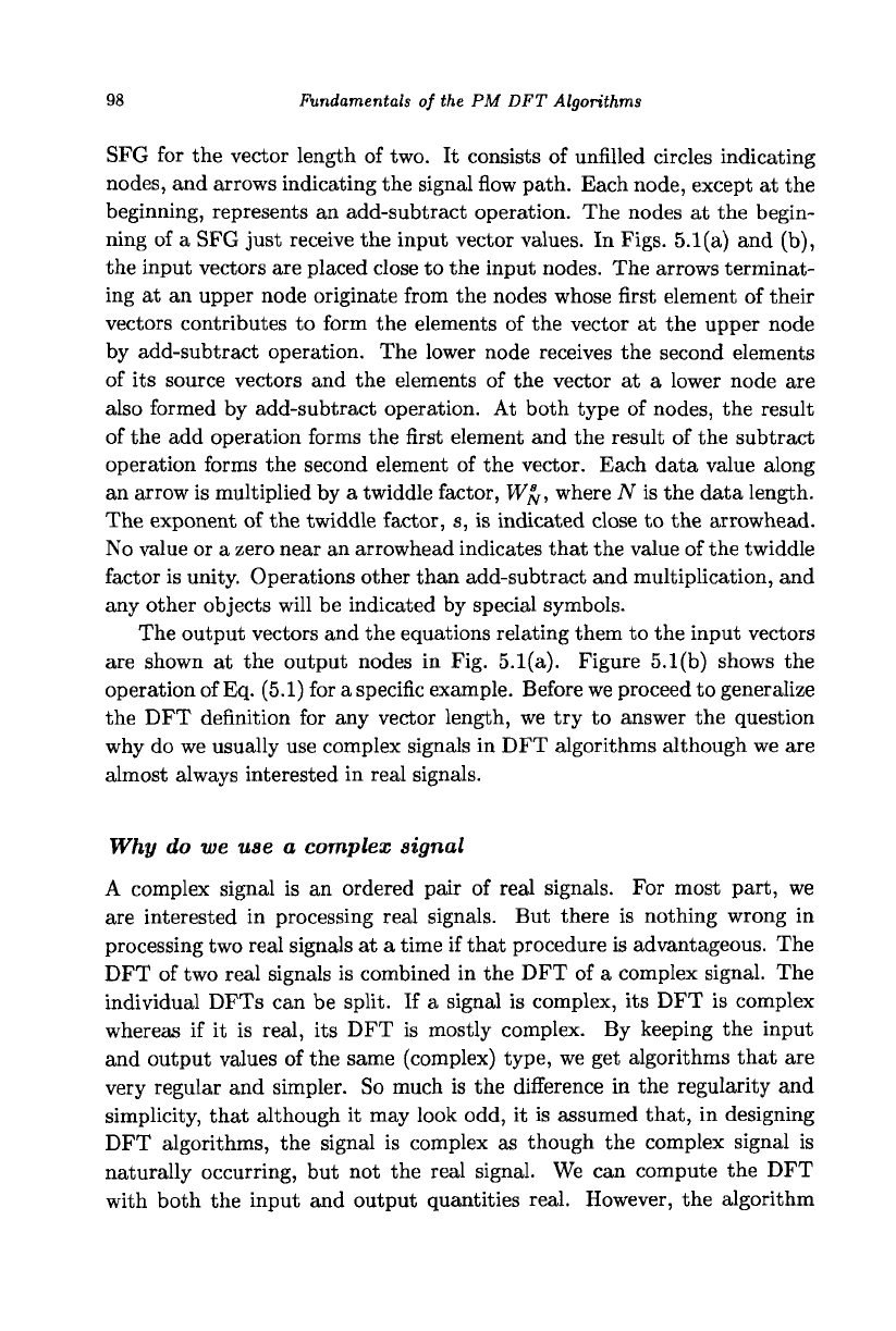
98
Fundamentals of the PM DFT Algorithms
SFG for the vector length of two. It consists of unfilled circles indicating
nodes,
and arrows indicating the signal flow path. Each node, except at the
beginning, represents an add-subtract operation. The nodes at the begin-
ning of a SFG just receive the input vector values. In Figs. 5.1(a) and (b),
the input vectors are placed close to the input nodes. The arrows terminat-
ing at an upper node originate from the nodes whose first element of their
vectors contributes to form the elements of the vector at the upper node
by add-subtract operation. The lower node receives the second elements
of its source vectors and the elements of the vector at a lower node are
also formed by add-subtract operation. At both type of nodes, the result
of the add operation forms the first element and the result of the subtract
operation forms the second element of the vector. Each data value along
an arrow is multiplied by a twiddle factor, W^, where N is the data length.
The exponent of the twiddle factor, s, is indicated close to the arrowhead.
No value or a zero near an arrowhead indicates that the value of the twiddle
factor is unity. Operations other than add-subtract and multiplication, and
any other objects will be indicated by special symbols.
The output vectors and the equations relating them to the input vectors
are shown at the output nodes in Fig. 5.1(a). Figure 5.1(b) shows the
operation of Eq. (5.1) for a specific example. Before we proceed to generalize
the DFT definition for any vector length, we try to answer the question
why do we usually use complex signals in DFT algorithms although we are
almost always interested in real signals.
Why do we use a complex signal
A complex signal is an ordered pair of real signals. For most part, we
are interested in processing real signals. But there is nothing wrong in
processing two real signals at a time if that procedure is advantageous. The
DFT of two real signals is combined in the DFT of a complex signal. The
individual DFTs can be split. If a signal is complex, its DFT is complex
whereas if it is real, its DFT is mostly complex. By keeping the input
and output values of the same (complex) type, we get algorithms that are
very regular and simpler. So much is the difference in the regularity and
simplicity, that although it may look odd, it is assumed that, in designing
DFT algorithms, the signal is complex as though the complex signal is
naturally occurring, but not the real signal. We can compute the DFT
with both the input and output quantities real. However, the algorithm
Vector Format of the DFT 99
will be irregular and practically inefficient. The reason is that representing
sinusoids by complex exponentials is natural and most efficient.
Vector format of the DFT
We present an equivalent vector format of Eq. (3.6) for any value of u,
where u is the vector length and it is a factor of N, the data length. For
following the derivation easily, apply each of the steps to the specific case
of TV = 8 and u = 2. The individual DFT equations with N = 8 are
given in Chapter 3. In addition, refer to the computation of the 4-point
DFT presented at the beginning of this section. Each sum of N products
in Eq. (3.6) can be rewritten as the sum of ^ products each of which is
formed using a sum of u products.
U—1 ,
r
U — 1 T.J
X(k) = W°
N
k
Y, x(0 + s-)W°
N
k
"
+Wk
k
J2
x
(
l
+
s
-)
W
N -+•" +
8=0 8=0
8=0
n=0 s=0 n=0 8=0
For each value of n, the inner summation is a u-point DFT and when
evaluated will give rise to u distinct values for k =
0,1,...,
u
—
1. Let
a(n),n =
0,1,...,
^
— 1
denote the nth input vector (Vectors will be shown
in boldface.) consisting of the u-point DFT values a
q
(n),
q =
0,1,...,
u
—
1
as defined below.
a(n) = {a
0
(n),ai(n),...A-iW}=Vi(n + 8-)B'
u
,
«,
z
—' u
8=0
0 = 0,1,...,u-l, n = 0,l,..., 1 (5.2)
u
Now, the last but one equation can be rewritten as
X(k) = J2 a
q
(n)W£
k
, fc = 0,l,...,iV-l
n=0
100
Fundamentals of the PM DFT Algorithms
Since the values of the u-point DFT a
q
(n) are periodic with a period of u,
for values of k equal to or greater than u, the values a
q
(n) repeat. Therefore,
q = k mod u
Replacing the variable k by k + p— in the last two equations, we get
£-1
X(k+p*) = ^ra,W^,i = 0,l,..,--l,
n=0
U
N
p =
0,1,...,
u
—
1, q = (k + p—) mod u
u
The N frequency coefficients X{k) can also be represented by ^ vectors
each with u elements. Let
A(k) = {A
0
(k),A
1
(k),...,A
u
_
1
(k)} = {X(k+p-)},
u
N
k =
0,1,...,
1, p =
0,1,...
,u - 1 (5.3)
u
With vector input quantities a
q
(n) as defined by Eq. (5.2) and vector output
quantities A
p
(k) as defined by Eq. (5.3), the DFT as defined by Eq. (3.6)
can be equivalently written as
A
p
(k)
= J2
WZ
n
a
q
(n)Wtf,
k =
0,1,...,
^ -
1
(5.4)
n=0
where q= (k+ p^) mod u and p =
0,1,...,
u
—
1. Thus, the use of vector
input and output quantities changes the form of the DFT definition from
Eq. (3.6) to Eq. (5.4).
Vector format of the DFT with u = 2
The use of vectors, each with two elements, provides the highest efficiency
since the frequency coefficients of a two-point DFT are the most closely
related. For the specific value of u = 2, Eqs. (5.2), (5.3), and (5.4) become,
respectively, as
N N
a(n) = {o
0
(n),ai(n)} = {x(n) + x(n+ -^),x(n) -x(n+ —)},
n = 0,l,...,y-l (5.5)
Direct Computation of the DFT with Vectors
101
A(k) = {MQMk)} = {X(k),X(k+ j)}, fc =
0,l,...,^-l
(5.6)
N
4(*) = £
(-l)
pn
a„(n)WZ
k
,
k =
0,1,...,--
1
n=0
(5.7)
where p — 0,1 and q = (k + py) mod 2. The vector format definition of
the 8-point DFT with u = 2 is shown below in matrix form.
A
p
(0)
4,(1)
4(2)
4(3)
- wi
wi wi wi'
wi wi wi wi
wi wi wi wi
. wi wi wi wi .
r
(-l)<*a,(0)
(-lWi)
(-1)
2
%(2)
L
(-l)
3
"a
9
(3)
(5.8)
5.2 Direct Computation of the DFT with Vectors
In this section, we present an implementation of the DFT expression,
Eq. (5.7), for N that is an integral multiple of 4. It can be easily modified
for an even N. This implementation will be useful for testing programs. For
these lengths, this implementation is much more efficient than that given
in Chapter 3.
The main module, shown in Fig. 5.2(a), invokes four modules to get the
computation done. The second module, shown in Fig. 5.2(b), sets up the
twiddle factor array tf of size JV, that is the computation and storage of the
sample values of the cosine function over one cycle, with argument starting
from zero with increment of ^. This module is called twid-fac. Variable i
is used as a loop counter and the loop is terminated when i equals N, the
data size. The setting up of the twiddle factor array can be made faster by
using identities such as cos(^(iV
—
n)) = cos(^n). Note that this module
can be eliminated by computing the values of the twiddle factors each time
they are required. However, it is costly in terms of run-time.
The next module, shown in Fig. 5.2(c), reads the real and imaginary
parts of the complex input data, respectively, into the arrays xr and xi,
each of size N, the data size. It is assumed that the real parts of the input
data are stored before the imaginary parts in the input file. If the data is
real, initialize the values of the array xi to zero and read the data into the
array xr. This module is called in-put.
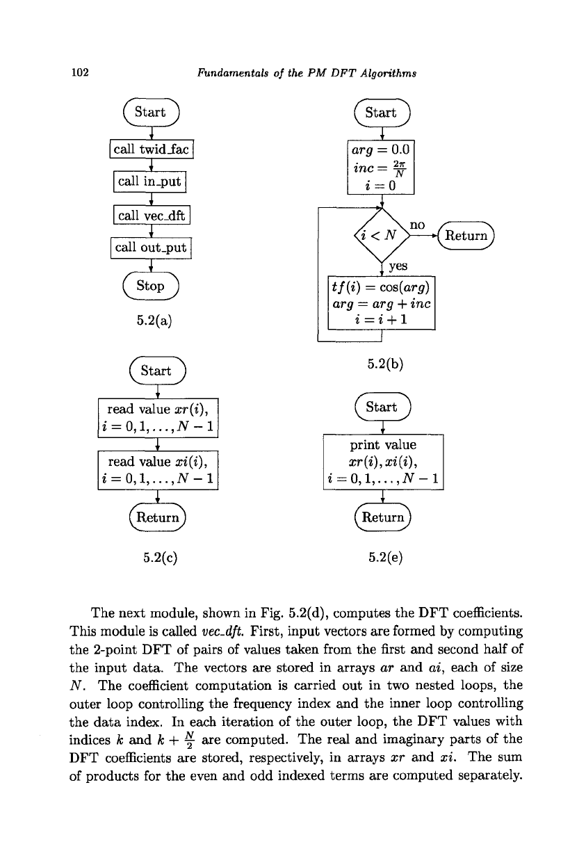
102 Fundamentals
of the PM DFT
Algorithms
( Start")
call twid_fac
I
call in.put
1
call vec_dft
1
call out_put
f Stop ^
5.2(a)
(start *)
read value ar(t),
i = 0,l,...,iV-l
1
read value
xi{i),
i =
0,l,...,N-l
(Return
J
('start
")
arp
= 0.0
mc
—
2ff
z
= 0
{^ReturnJ
tf(i)
=
cos(arg)
arg
—
arg + inc
i
= i + l
5.2(b)
Tstart J
print value
xr(i),xi(i),
i
=
0,l,...,N-l
X
5.2(c)
(Return)
5.2(e)
The next module, shown
in
Fig. 5.2(d), computes
the DFT
coefficients.
This module
is
called vec-dft. First, input vectors
are
formed
by
computing
the 2-point
DFT of
pairs
of
values taken from
the
first
and
second half
of
the input data.
The
vectors
are
stored
in
arrays
ar and ai,
each
of
size
N. The
coefficient computation
is
carried
out in two
nested loops,
the
outer loop controlling
the
frequency index
and the
inner loop controlling
the data index.
In
each iteration
of the
outer loop,
the DFT
values with
indices
A;
and k + y are
computed.
The
real
and
imaginary parts
of the
DFT coefficients
are
stored, respectively,
in
arrays
xr and xi. The sum
of products
for the
even
and odd
indexed terms
are
computed separately.
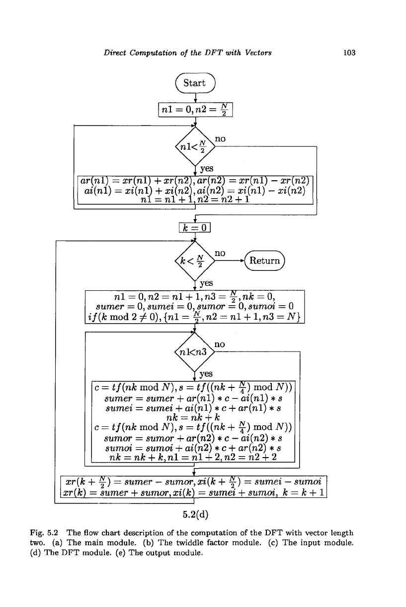
Direct Computation of the DFT with Vectors
('start')
nl = 0,n2 =
N
no
ar(nl)
—
xr(nl) + xr[n2),ar(n2) = xr(nl)
—
xr{n2)
ai(nl) = xi(n
1) + xi(n2),ai{n2)
i,l = nl + l,n2 = r
= xi(nl)
—
xi(n2)
h2 + l
( Return)
nl = 0, n2 = nl + 1, n3 = y,nfc = 0,
sumer = 0, sumei = 0, sumor = 0, sumoi = 0
i/(fc mod 2 ^ 0), {nl = f, n2 = nl +
1,
n3 = iV}
c = t/(n& mod iV), a = */((nfc + f) mod JV))
sumer = sumer + ar(nl) * c - oi(nl) * s
sumei = sumei + ai(nl) * c + ar(nl) * s
c = i/(nfc mod N), s = tf((nk + f) mod N))
sumor = sumor + ar(n2) * c
—
ai{n2) * s
sumoi = sumoi + ai(n2) *c + or(n2) * s
nk = nk + k, nl = nl +
2,
n2 = n2 + 2
_L
xr(k + ~) = sumer
—
sumor,xi(k + y) = sumei
—
sumoi
Tl^r
xr(k) = sumer + sumor,xi(k) — sumei + sumoi, k = k + 1
5.2(d)
Fig. 5.2 The flow chart description of the computation of the DFT with vector length
two.
(a) The main module, (b) The twiddle factor module, (c) The input module.
(d) The DFT module, (e) The output module.