Smith G.T. Cutting Tool Technology: Industrial Handbook
Подождите немного. Документ загружается.


the ratio of chip width-to-thickness), will change and
this has a deleterious eect on the insert’s chip-break-
ing ability.
2.5.4 Helical Chip Formation
Conventional Turning
For the general turning operations, such as sliding (i.e.
Z-axis tool feeding) and facing (i.e. X-axis tool path
motions), the chip is rolled into a helix, simply because
the chip edges are formed from dierent rotation radii
(Fig. 34d). Here, the two edges of the chip consume
dierent quantities of workpiece material, creating dif-
fering edge lengths, coupled to the fact that a varia-
tion in cutting speed is present, these relationships will
result in a helical chip formation. e appearance of
the chip’s helix depends upon the workpiece’s diameter
and its metallurgical specication/condition, which
means the chip helices are extremely dicult to quan-
tify.
Most common types of helical chip diameters are
determined either directly by the initial curvature
from its origin, or are the result of additional bending,
introduced by the chip-breaker. For example, the heli-
cal chip type shown in Fig. 34c (le), has its chip seg-
ments turned inwards, this being a desirable chip form
when not fully developed, that is prior to the rst coil
being completed. Whether, or not the chip is of this
form will already be determined even before it meets
the chip-breaker, this being the result of its cross-sec-
tion and the natural tendency to bend according to the
‘line of least resistance’. If the chips width is no larger
than its thickness, for example, the resistance to bend-
ing in the segment-stiened thickness direction is
larger than in the width direction. In this case, unless
this kind of chip is broken early, by colliding with ei-
ther part of the tool, or the workpiece whilst it is still
sti and short – called ‘self-breaking’ – a helical chip
will be formed. In this case, the barbed, or serrated
edge is turned outwards causing additional bending,
this being introduced by the chip-breaker. For exam-
ple, the helical chip type shown in Fig. 34c (right),
becomes dicult and awkward to control. is out-
ward-curving helical chip also has weakened sections
in the serrations between the chip segments, but ap-
plied loads on it are readily absorbed by the spring ac-
tion of the chip. is type of chip will break as it hits
the insert’s ank face (see Fig. 27b)
32
. Only today’s very
complex chip-breaker designs can reduce these out-
ward-curling helical chips. Although such chip helices
produced by combinations of the feeds and D
OC
’s that
result in the chip width being too small in relation to
its thickness must be avoided.
Grooving and Recessing
In conventional turning operations, it is signicantly
easier to form a manageable chip, than for features re-
quiring either grooving, or recessing. e chip formed
during plunge grooving counter-rotates in relation
to the workpiece, whereby it does not experience the
same twisting force as chips produced by either Z-, or
X-axes turning operations. When grooving, ideally the
c
hip resembles a ‘watch spring’ , indicating that the chip
is curling back onto itself and will ultimately break in
several distinct ways: such as at the completion of the
grooving cycle, or due to friction between the chip and
its groove side walls – as the chip diameter becomes
greater. In grooving operations, three signicant fac-
tors aect chip control, these are:
(
i) Insert geometry – applied to the rake face, can be
classied into distinct groupings:
•
Radial-ground top rake (not shown), producing
the desired ‘watch-spring’ chip formation. is
grooving insert geometry will not thin the chip,
therefore surface nish passes are necessary on
both groove side walls.
NB F
or long-chipping materials the chip-former
does not provide enough resistance to produce chip
curling, hence, a straight at chip occurs, that may
32 One of the problems with this type of chip-breaking, is the
potential for secondary wear on the insert’s non-cutting zone
on the face, caused by the chip helix breaking locally against
this face. Such an occurrence happens when the chip helix at-
tains such a diameter and pitch that its free-end continually
strikes the non-cutting portion of the insert’s edge – termed
‘chip-hammering’ – causing the edge to be locally weakened
and to subsequently crumble.
NB Chip-hammering can be alleviated by slightly increasing
the helix diameter (i.e. by somewhat modifying the cutting
data) causing the chip to break against the tool’s ank – be-
low the insert’s cutting edge, this being one of the previously
employed and favoured chip-breaking mechanisms, as shown
in Fig. 27b.
Turning and Chip-breaking Technology 71
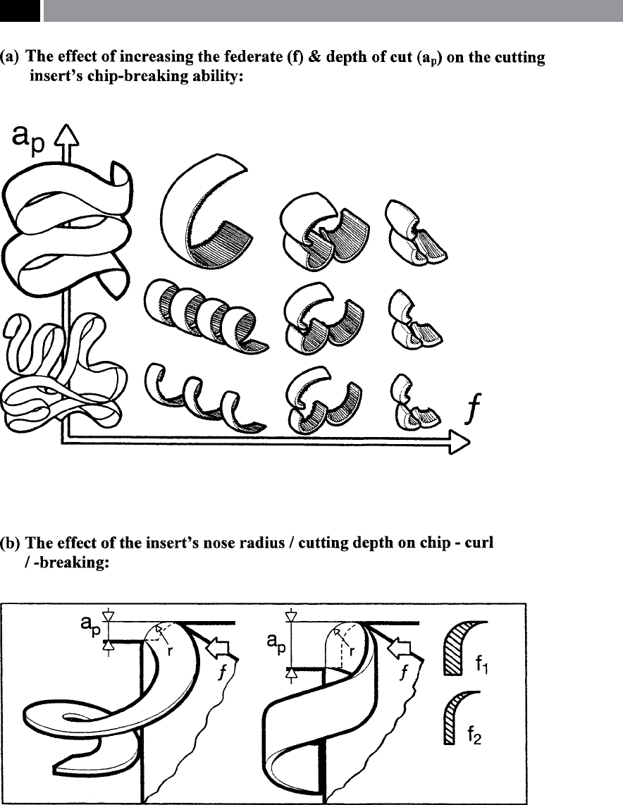
Figure 35. The chip-breaking envelopes related to cutting data and chip-curling behaviour. [Courtesy of
Sandvik Coromant]
.
72 Chapter 2

wrap itself around either the tool, or workpiece, but
such a geometry is perfect for machining alumin-
ium, or non-ferrous materials.
•
Radial top rake (illustrated in Fig. 4 middle and
to the le – three grooving insert sizes illustrated).
is radial top rake is designed to thin the chip.
Such chip thinning, eliminates the need to under-
take nishing passes on the groove’s side walls. Fur-
thermore, this type of grooving insert geometry be-
ing on-centre, enables axial turning of diameters for
wide shallow grooves
33
, or recesses.
•
Raised bumps on top rake (see Fig. 27a – le).
is sophisticated grooving geometry is utilised for
materials where chip control is dicult, as it pro-
vides an ‘aggressive barrier’ to the curling chip. e
raised bumps force the chip back onto itself, either
producing a tightly curled watch-spring chip, or
causes the chip to break.
(
ii) Surface speed of the workpiece – in order to ob-
tain full advantage of a grooving insert’s chip-form-
ing abilities, the chip must be allowed to ow into the
chip-former. is chip-ow can be achieved by either
decreasing the workpiece’s surface speed, or increasing
the feed – more will be said on this shortly. e former
technique of decreasing the surface speed, allows the
material to move slower across the top rake of the cut-
ting edge and as a result, has greater contact time to
engage the chip-former. is slower workpiece speed,
has the benet of increasing tool life, through lower
33 A groove, or recess, can normally be considered as a straight-
walled recessed feature in a workpiece, as illustrated in Fig.
40. Typical applications for grooves are to provide thread re-
lief – usually up to a shoulder – so that a mating nut and its
washer can be accurately seated , or for retaining O-rings. As
the groove is produced in the workpiece, the tool shears away
the material in a radial manner, via X-axis tool motion. e
chip formed with insert geometries having a at top rake, will
have an identical width as the tool and can be employed to
‘size’ the component’s width feature. However, this chip action
– using such a tool geometry, creates high levels of pressure
at the cutting edge as a result of the chip wall friction, which
tends to produce a poor machined surface texture on these
sidewalls. Grooving with an advanced chip-former insert ge-
ometry, reduces the chip width and provides an ecient cut-
ting action, this results in decreasing the cutting edge pressure
somewhat. Chip-formers oer longer tool life and improved
sidewall nishes with better chip control, than those top-rakes
that have not incorporated such insert chip-forming geomet-
ric features.
tool/chip interface temperatures. e negative factors
of such a machining strategy, are that the:
•
Part cycle times are increased and as a result, any
batch throughput will be lessened,
•
As the cutting edge is in contact for a longer du-
ration, more heat will be conducted into the tool,
than into the chip, which could have a negative im-
pact of inconsistent workpiece size control,
•
Due to the lower workpiece surface speed, the ben-
ets of the insert’s coating will be reduced, as such
coating technology tends to operate more eec-
tively at higher interface temperatures.
(
iii) Increasing the feedrate – by increasing the feed
allows it to engage the chip-former more eectively
– this being the preferred technique for chip control. A
heavier applied feedrate, produces a chip with a thicker
cross-section. Further, a thicker chip engages the in-
sert’s geometry with higher force, creating a greater
tendency to break. Hence, by holding a constant work-
piece surface speed, allows the faster feedrate to reduce
cycle times.
Transversal, or Face Grooving
Transversal grooving geometry has a curved tear-
shaped blade onto which, the insert is accurately lo-
cated and positioned. e transversal insert follows
the 90° plunged feed into the rotating face of a work-
piece. ese tools are categorised as either right-, or
le-hand, with the style adopted depending upon
whether the machine tool’s chuck rotates anti-clock-
wise (i.e. using a right-hand tool), or clockwise (i.e.
le-hand). e minimum radius of curvature for such
transversal grooving tooling is normally about 12mm,
with no limit necessary on the maximum radial curva-
ture that can be machined. For shallow face grooves,
o-the-shelf tooling is available, but for deep angular
face grooves they require specialised tools from the
tooling manufacturers.
If a relatively wide face groove requires machining
with respect to the insert’s width, then the key to suc-
cess here, is establishing where in the face to make the
rst plunge. is initial face plunge should be made
within the range of the tool’s diameter, otherwise the
tool will not have sucient clearance and will ulti-
mately break. Successive plunges to enlarge the face
groove should be made by radially moving the insert
0.9 times the insert’s width, for each additional plunge.
e rotational speed for face grooving is usually about
80% of the speed used for parting-o – soon to be
Turning and Chip-breaking Technology 73

mentioned. Feedrates are normally around 50% of
parting-o values, with the proviso that for material
which is subject to work-hardening, minimum feeds
are necessary.
In transversal grooving operations, a unique chip
form occurs, because the chip is longer the further
away it is from the workpiece’s centre line of rotation.
is results in the chip which no longer ows in a
straight line across the insert’s edge, instead it moves
at an angle. Such a naturally curved chip is dicult to
exhaust from the face groove, particularly if it is bro-
ken. Hence, no attempt should be made to break the
chip. For deep and narrow grooves, the best solution
is to retract the tool at short intervals, to check that
the blade shows no signs of rubbing, this is to guard
against any likely breakage that might occur when
machining outside the blade’s range. Due to the fact
that transversal grooving tooling is susceptible to chat-
ter
34
, any excessive overhang of the tool should be mi-
nimised. e chip should never be allowed to become
entangled within the transversal groove and should be
ejected speedily, otherwise the tool is likely to break.
34 Chatter is a form of self-excited vibration and such vibrations
are due to the interaction of the dynamics of the chip-removal
process, together with the structural dynamics of the machine
tool. Such chatter, tends to be at very high amplitude, which
can result in either damage to the machine tool, or lead to pre-
mature tool failure. Typically, chatter is initiated by a distur-
bance in the cutting zone, for several reasons, such as:
Lack of homogeneity – in the workpiece material (i.e. typi-
cally a porous component, such as is found in a Powder
Metallurgy compact),
Workpiece surface condition (i.e. typically a hard oxide scale
on a hot-rolled steel component, utilsing a shallow D
OC
),
Workpiece geometry (i.e. if the component shape produces
either a variation in the D
OC
– for example, because of un-
even depth of casting material being machined, or light cuts
on interrupted shapes, such as hexagon, square, or rectan-
gular bar stock),
Frictional conditions (i.e. tool/chip interface frictional
variations, whilst machining).
Regenerative chatter is a type of self-excited vibration, result-
ing from the tool cutting a workpiece surface that has either
signicant roughness, or more likely the result of surface dis-
turbances from the previous cut. ese disturbances in the
workpiece surface, create uctuations in the cutting forces,
with the tool being subjected to vibrations with this process
continuously repeating, hence the term ‘regenerative chatter’.
Self-excited vibrations can be alleviated by either increas-
ing the dynamic stiness of the system, or by increasing the
damping.
NB Dynamic stiness can be dened as the ratio of the am-
plitude of the force to the vibrational amplitude.
–
–
–
–
For any face grooving of workpiece material that is
subject to a continuous chip formation, always use
copious amounts of coolant and at high-pressure – if
possible, to not only lubricate the cutting zone, but to
aid in chip ushing from this groove.
Par ting-off
e parting-o process is normally considered to be a
separate machining operation, but it simply consists of
cutting a groove to centre of rotation of the workpiece,
to release it from the bar stock, or to ‘part-o ’ to a pre-
viously formed internal diameter (shown in Fig. 40 for
le-hand side operations). Essentially in a parting-o
operation, two time-periods are worthy of mention,
these are:
(
i) At separation from the bar stock – a lower spindle
speed than was previously used on the workpiece, will
prevent the ‘released part’ from hitting the machine
and potentially damaging its surface. Moreover, it al-
lows an operator – if present – to hear the change in
the lower spindle speed tone, as it is about to separate
from the bar stock, avoiding the parting-o tool from
getting ‘pinched’ between the stock and the soon-
to-be-released component. Oen, ‘Part-catchers’ are
utilised to reduce any surface damage to the falling
component, once it has been parted-o.
N
B If the component to be parted-o is held in a co-
axial/sub-spindle, at component release, the additional
spindle supports the workpiece and under these con-
ditions, the parting-o operation is virtually identical
to that of found in a grooving cycle.
(
ii) Surface speed reduction – this eectively oc-
curs when the machine’s spindle attains its maximum
speed. For example, on a machine tool having a maxi-
m
um speed of 3,000 rpm, 90 m min
–1
would only be
achievable until the parting diameter has reached
a
bout 8.6 mm. When parting to a smaller diameter
than 8.6 mm, the surface speed would decrease at a
xed spindle speed. As the parting diameter reaches
5
.8 mm the surface speed would be 55 m min
–1
, or 60%
of the ideal, thus signicantly increasing the chip load-
ing as the tool approaches the workpiece’s centreline.
In order to alleviate the increasing tool loading, lower-
ing the feedrate by about 50% until separation is just
about to occur, then nally dropping the surface speed
to almost zero at this point, reduces the tendency for a
‘pip’ to be present on the workpiece. On a CNC driven
spindle, it is not advisable for parting-o operations,
74 Chapter 2

to utilise the ‘canned cycle’ such as the ‘constant surface
speed’
35
function.
NB A more serious parting-o problem has been that
in order to eliminate the pip formed at the centre of the
‘
released component’ , some tools have been ground
with the front edge angle of between 3° to 15°. Such
a front edge geometry, can introduce an axial cutting
force component, leading to poor chip control, which
in turn, causes the tool to deect. is parting-o tool
deection, can lead to the component’s face ‘dishing’ ,
creating a convex surface on one face and a concave
surface on the other – so this tool grinding strategy
should be avoided.
Today, parting-o inserts normally consist of two
main types with top rakes that are either of, negative,
or positive cutting edge chip-forming geometries. e
negative-style of chip-formers are possibly the most
commonly utilised. ese inserts have a small nega-
tive land at the front edge which increases the insert’s
strength, giving protection in adverse cutting condi-
tions, such as when interrupted cutting is necessary
during a parting-o operation. e land width – oen
termed a ‘T-land’ ,
is relative to the breadth of the part-
ing-o tool. is width of the insert’s land has a direct
correlation to the feedrate and its accompanying chip
formation. e feedrate must be adequate to force the
workpiece material over the land and into the chip-
former
36
.
Notwithstanding the widespread usage of negative
parting-o tooling, positive-style insert geometries
have some distinct advantages. e chief one being the
ability to narrow the chip at light feedrates, with mini-
35 ‘Constant surface speed’ CNC capability as its name implies,
allows the machine tool to maintain a constant surface speed
as the diameter is reduced. e main problem with using
this ‘canned cycle’ , is that as the maximum spindle speed is
reached, the chip load will also increase. is is not a prob-
lem, so long as the maximum speed has not occurred, such as
when parting-o a component with a large hole at its centre.
36 Parting-o operations that employ a negative-style insert (i.e.
with a land and accompanying chip-former), normally have
the feedrate determined in the following manner: by multi-
plying the width of the insert by a constant of 0.04. For ex-
a
mple, for a 4 mm wide tool, it is necessary to multiply the
insert’s width of 4 mm by 0.04 to obtain a feedrate of 0.16 mm
rev
–1
. is will give a ‘start-point’ for any parting-o opera-
tions, although it might be prudent to check this feedrate is
valid, from the tooling manufacturer’s recommendations.
mal tool pressure. If excessive tool pressure occurs,
this can promote work-hardening of the ‘transient
surface’
37
of the workpiece. ese abilities are impor-
tant points when machining relatively low mechanical
strength components, which might otherwise buckle
if machined with negative-style inserts when subse-
quently parted-o.
Positive cutting edge parting-o tooling having
chip-formers, are ideal for applications on machine
tools when either low xed feedrates are utilised, or
if the workpiece material necessitates lower cutting
speeds. is positive-style of parting-o tooling, oper-
ates eciently when machining soer workpiece mate-
rials, such as: aluminium-or, cooper-based alloys and
m
any non-metallic materials, typically plastics. Feed-
rates can be very low with these positive-type part-
i
ng tools, down to 0.0254 mm rev
–1
with exceptional
chip control and consistent tool life. One major dis-
advantage of using these positive tooling geometries
for parting-o, is that the tool is much weaker than its
equivalent negative geometry type.
e concept of insert self-grip in its respective tool-
holder, was developed by the cutting tool manufac-
turer Iscar tools in the early 1970’s and has now been
adopted by many other tooling manufacturers (Fig. 40
top le-hand side). ese ‘self-grip’ tooling designs,
rely on the rotation of the part and subsequent tool
pressure to keep the ‘keyed and wedged’ insert seated
in its respective toolholder pocket. Previously, double-
ended inserts termed ‘dogbones’ ,
were oen used but
were limited to low D
OC
’s – due to the length of the
secondary cutting edge, so have been somewhat over-
shadowed by the ‘self-grip’ varieties of parting-o
tooling.
2.5.5 Chip Morphology
The Characterisation of Chip Forms (Appendix 2)
In the now withdrawn ISO 3685 Standard on Ma-
chinability Testing Assessment, of some interest was
the fact that this Standard had visually characterised
37 Transient surfaces are those machined surfaces that will be
removed upon the next revolution of either the:
Workpiece (i.e in rotating part operations), or
Cutter (i.e. for rotating tooling – drilling, milling, reaming,
etc.).
–
–
Turning and Chip-breaking Technology 75

chip forms under eight headings, with several varia-
tions appearing in each groups (i.e. see Appendix 2
for an extract showing these chip form classications).
Although in the main, the chip forms were related to
turning, some of these chip morphologies could be ex-
trapolated to other manufacturing processes. e chip
type that will be formed when any machining opera-
tion is undertaken is the product of many interrelated
factors, such as:
•
Workpiece material characteristics – will the mate-
rial that forms the chip signicantly work-harden?,
•
Cutting tool geometry – changing, or modifying the
cutting insert geometries
38
and its plan approach
angles will have a major inuence on the type of
chip formed,
•
Temperatures within the cutting zone – if high, or
low temperatures occur as the chip is formed, this
will have an impact on the type of chip formed,
•
Machine tool/workpiece/cutting tool set-up – if
this ‘loop’ is not too rigid, then vibrations are likely
to be present, which will destabilise the cutting
process and aect the type and formation of chips
produced,
•
Cutting data utilised – by modifying the cutting
data: feeds and speeds and D
OC
’s, with the insert ge-
ometry maintained, this can play a signicant role
in the chip formed during machining operations.
NB Chip formation has become a technology in
its own right, which has shown signicant devel-
opment over the last few decades of machining ap-
plications.
As has been previously mentioned, chip formation
should always be controlled, with the resultant chips
formed being broken into suitable shape formation,
s
uch as ‘spirals and commas’ , as indicated by the re-
sultant chip morphology shown in Fig. 35a. Uncon-
trolled chip-steaming (i.e. long continuous workpiece
strands), must be avoided, being a signicant risk-fac-
tor to both the: machine tool’s operation and its CNC
setter/operator alike.
38 Chip-breaking envelopes (see Fig. 34 middle right), are the
product of plotting both the feedrate and D
OC
on two axes,
with their relative size and position within the graphical area
being signicantly aected by the cutting insert’s geometry
– as depicted by the three cutting insert geometric versions
shown by types: A, B and C (Fig. 34).
For every cutting insert geometry, there is a recom-
mended application area – termed its ‘chip-breaking
envelope’ (i.e. see footnote 38 below) – with regard to
its range of feedrates and D
OC
’s. Within this ‘envelope’ ,
chips of acceptable form are produced by the cut-
ting insert’s geometry. Conversely, any chips that are
formed outside this ‘envelope’ are not acceptable, be-
cause they are either formed as unbroken strands, or
are too thick and over-compressed. When component
proling operations are necessary (Fig. 31a), this nor-
mally involves several machining-related parameters:
variations in D
OC
’s, together with path vectoring of the
feeds and as a result of this latter point, changes to the
resultant chip’s path on the rake face. ese factors are
important as they can modify the chip morphology
when proling operations include: recessed/undercut
shoulders, tapers and partial arcs, facing and sliding
operations with the same tool, together with many
other combined proled features. All of these opera-
tions make signicant demands on the adaptability of
the cutting insert’s geometry to eciently break the
chip.
In general, the cutting insert’s chip formation prin-
ciples are concerned with the chip-breaker’s ability to
create a chip form that is neither not too tight a curl,
nor too open.
If chip curling is too tight for the specic machin-
ing application, the likely consequences are for a chip
form creating:
•
‘Chip-streaming’ – producing long chip strands
that are undesirable, wrapping itself around the
machined surface of the workpiece with work-
hardened swarf and possibly degrading this ma-
chined surface, or may become entangled around
the various parts of the machine tool, which could
impede its operation,
•
Excessive heat generation – this can decrease tool
life, or be conducted into the machined part and
consequently may aect specic part tolerances for
the individual part, or could lead to modications
in the statistical variability
39
of a batch of parts,
39 Statistical variability in component production can cause
variations from one part to another, as the standard deviation
and mean changes, these important factors will be mentioned
later in the text.
76 Chapter 2

•
Increased built-up edge (BUE) formation – which
through ‘
attrition wear’
40
may cause the risk of pre-
mature cutting edge failure.
When the chip curling is too open, this may result in
the following negative tendencies:
•
Poor chip control – creating an inecient chip-
breaking ability by the cutting insert,
•
Chip hammering – breaking down the edge and
causing it to crumble and as a result creating the
likelihood of prematurely failing,
•
Vibrational tendencies – aecting both the ma-
chined surface texture and shortening tool life.
Chip formation and its resultant morphology, is not
only aected by the cutting data selected, but will be
inuenced by the plan approach (i.e. entering) angle
of the insert. In most machining operations, they are
usually not of the orthogonal, but oblique cutting in-
sert orientation, so the aect is for the entering angle
to modify the chip formation process. e insert’s en-
tering angle aects the chip formation by reducing the
chip thickness and having its width increased with a
smaller angle. With oblique cutting geometry, the chip
formation is both ‘smoother and soer’ in operation as
the plan approach angle tends toward say, 10° to 60°,
furthermore, the chip ow direction will also advanta-
geously change with the spiral pitch increasing.
As the nose radius is changed with dierent cutting
inserts, this has the eect of changing both the direc-
tion and shape of the chips produced. is nose radius
geometry is a fundamental aspect in the development
of chips during the machining process – as depicted by
Fig. 35b. Here, an identical nose radius and feedrate
is utilised, but the dierence being the D
OC
’s, with a
shallow D
OC
in Fig. 35b (le), giving rise to a slow chip
helix, whereas in Fig. 35b (right) the D
OC
is somewhat
deeper, creating a tighter chip helix which is bene-
cial to enhanced chip-breaking ability. Shallow cutting
depths produce ‘comma-shaped’ chip cross-sections,
40 Attrition wear is an unusual aspect of tool wear, in that it is
the result of high cutting forces, sterile surfaces, together with
chip/tool anity, creating ‘ideal’ conditions for a pressure
welding situation. Hence, the BUE develops, which builds-up
rapidly and is the ‘swept away’ by the chip ow streaming over
the top rake’s surface, taking with it minute atomic surface lay-
ers from the tool’s face. is continuous renewal and destruc-
tion of the BUE, enhances crater wear formation, eventually
leading to premature cutting edge failure.
having a small angle when compared to the cutting
edge. Equally, a larger depth means that the nose ra-
dius has somewhat less aect from its radius and
greater inuence by the entering angle of the cutting
edge, producing an outward directed spiral. Feedrate
also aects the width of the chip’s cross-section and its
ensuing chip ow
41
.
Chip formation begins by the chip curving, this be-
ing signicantly aected by combinations of the cut-
ting data employed, most notably: feedrate, D
OC
, rake
angle, nose radius dimensions and workpiece condi-
tion. A relatively ‘square’ cross-sectional chip nor-
mally indicates that an excessively hard chip compres-
sion has occurred, whilst a wide and thin band-like
chip formation is usually indicative of long ribbon-like
chips producing unmanageable swarf. If the chip curve
is tight helix, coupled to a thick chip cross-section,
this means that the length of the chip/tool contact has
increased, creating higher pressure and deformation.
It should be noted that excessive chip cross-sectional
thickness, has a debilitating eect on any machining
process. By careful use of CAD techniques coupled
to FEA to construct the insert’s cutting edge, comma-
shaped chips are the likely product of any machining,
providing that the appropriate cutting data has been
selected. In some machining operations, chip forma-
tion can be superior using a slightly negative insert
rake angle, thereby introducing harder chip compres-
sion and self-breaking of the chip, particularly if utilis-
ing small feeds. Conversely, positive rakes can be give
other important machining advantages, depending
which chip form and cutting data would be the most
advantageous to the part’s ensuing manufacture. Usu-
41 Chip-ow is the result of a compound angle between the chip’s
side- and back-ow. e chip’s side-ow being a measure of the
ow over the tool face (i.e. for a at-faced tool), whilst back-
ow establishes the amount of chip-streaming into the chip-
breaker groove. Detailed analysis of chip side-ow (i.e. via
high-speed photography), has indicated that it is inuenced
by a combination of groove dimensions and cutting data. If
the feedrate is increased, this results in a higher chip back-
ow angle, promoting chip-streaming into the chip-breaker
groove. e ratio of feed-to-length of restricted contact has
been shown to be an important parameter in the determina-
tion of chip- back-ow. Typically with low feedrates the cor-
responding chip back-ow is going to be somewhat lessened,
resulting in poor chip-breaker utilisation. When the restricted
contact between the chip and the tool is small – due to low
feed – the chip-ow does not fully engage the chip-breaker
and will as a result curve upward, with minimal ‘automatic’
chip-breaking eect.
Turning and Chip-breaking Technology 77
ally, for larger feedrates, a positive insert rake angle
might optimise the chip-curving tendency, by not pro-
ducing and excessively tight chip helix. Chip curve, its
resultant chip ow direction, the chip helix and its ac-
companying shape are designed into each cutting edge
by the tooling manufacturers. Tool companies ensure
that a controlled chip formation should result if they
are exploited within the recommended cutting data
ranges specied.
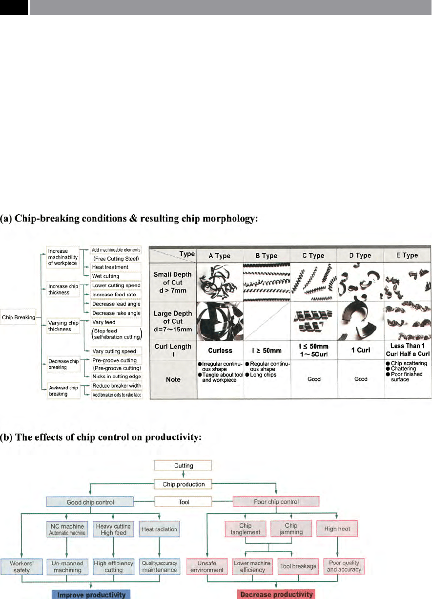
In Fig. 36a (le), eective chip-breaking decision-
making recommendations are shown on a ow-chart,
indicating how to obtain the desired chip-break-
ing control. In the chart shown in Fig. 36a (right),
the D
OC
’s indicate on the associated visual table the
expected chip type showing that here types ‘C and
D’ oer ‘good’ broken chips. Such chip morphology
charts as these from tooling manufacturers, attempt
to inform the user of the anticipated chip-breaking
if their recommendations are followed. Whereas the
ow-diagram illustrated in Fig. 36b, indicates that
‘good chip control’ improved productivity will result,
if a manufacturing company adopts the machining
Figure 36. Chip-breaking control and chip morphology and its aect on productivity. [Courtesy of Mitsubishi Carbide].
78 Chapter 2

strategy high-lighted to the le-hand side. On the con-
trary, ‘poor chip control’ with an attendant decrease in
productivity will occur, if the problems shown to the
right-hand side transpire.
Chip morphology can indicate important aspects
of the overall cutting process, from the cutting edge’s
geometry and its design, through to work-hardening
ability of the workpiece. Many other factors concern-
ing cutting edge’s mechanical/physical properties can
be high-lighted, these being important aids in deter-
mining a material’s machinability – which will be dis-
cussed in more depth later in the text.
2.5.6 Chip-Breaker Wear
Any form of tool failure will depend upon a combi-
nation of dierent wear criteria, usually with one, or
more wear mechanisms playing a dominant role. Pre-
viously, it was found that the workpiece surface texture
and the crater index act as appropriate tool failure cri-
teria, particularly for rough turning operations. More-
over, tool life based upon these two factors, approxi-
mated the failure curve more exactly than either the
ank, or crater wear criterion.
In cutting tool research activities, it has been found
that when machining with chip-breaker inserts, ank
wear (i.e. notably V
B
) is not the most dominant factor
in tool failure. In most cases, the ‘end-point’ of use-
ful tool life occurs through an alteration of the chip-
groove parameters, well before high values of ank
wear have been reached. e two principal causes of
wear failure for chip-breaker inserts are:
•
For recommended cutting data with a specic in-
sert, the design and positioning of chip-breakers/
grooves may promote ‘unfavourable’ chip-ow, re-
sulting in wear in the chip-breaker wall – causing
consequent tool failure,
•
Alterations in the cutting data, particularly feedrate,
aects chip-ow, which in turn, generates various
wear patterns at the chip-breaker’s heel and edge
(see Fig. 37).
In the schematic diagrams shown in Fig. 37, are il-
lustrated the concentrated wear zones on the: back
wall (i.e. heel), cutting edge, or on both positions for
a typical chip-breaker insert. Under the machining
conditions for Fig. 37a, the chip-groove utilisation
is very low, with the chip striking the heel directly.
us, as machining continues, this results in abrasive
wear of the heel and ultimately this heel becomes
attened and chip-breaking is severely compromised.
Conversely, when the cutting data produces a wear
zone concentrated at the insert’s edge (Fig. 37b), then
chip side-ow occurs and poor chip-breaking results,
together with low tool life. is accelerated tool
wear, resulting from an extended tool/chip contact
region over the primary rake face, promotes a rough
surface texture to the machined part. In the case of
Fig. 37c, these are ideal conditions for optimum chip-
breaking action and a correspondingly excellent and
predictable tool life, because the wear zones at both
the heel and edge are relatively uniform in nature,
illustrating virtually a perfect chip-forming/-breaking
action.
Higher tool/chip interface temperatures can result
as the heel wears, forming a crater at the bottom of the
chip-breaker groove. Combination wear – as shown in
Fig. 37c – generally results in signicantly improved
tool wear, in conjunction with more predictable tool
life. In the photographs of chip-breaker grooves shown
for an uncoated and coated Cermet cutting insert ma-
terial in Figs. 38a and b respectively, the relative wear
patterns can clearly be discerned. In the case of Fig.
38a – the uncoated insert – the predominant wear
concentration is primarily at the edge, indicating that
the cutting data had not been optimised. While in the
case of the coated Cermet insert of identical geometry
(Fig. 38b), the wear is uniform across the: edge, groove
and heel. is would seem to suggest that ideal cutting
data had been utilised in its machining operation. In
both of these cases some ank wear has occurred, but
this would not render the chip-breaking ability when
subsequent machining invalid.
N
B A complex matrix occurs (i.e. Fig. 38c) with Cer-
mets, this ‘metallurgy’ can be ‘tailored’ to meet the
needs of specic workpiece and machining require-
ments.
2.6 Multi-Functional Tooling
e concept of multi-functional tooling was devel-
oped from the mid-1980’s, when multi-directional
tooling emerged. is tooling allowed a series of op-
erations to be performed by a single tool, rather than
many, typically allowing: side-turning, proling and
Turning and Chip-breaking Technology 79
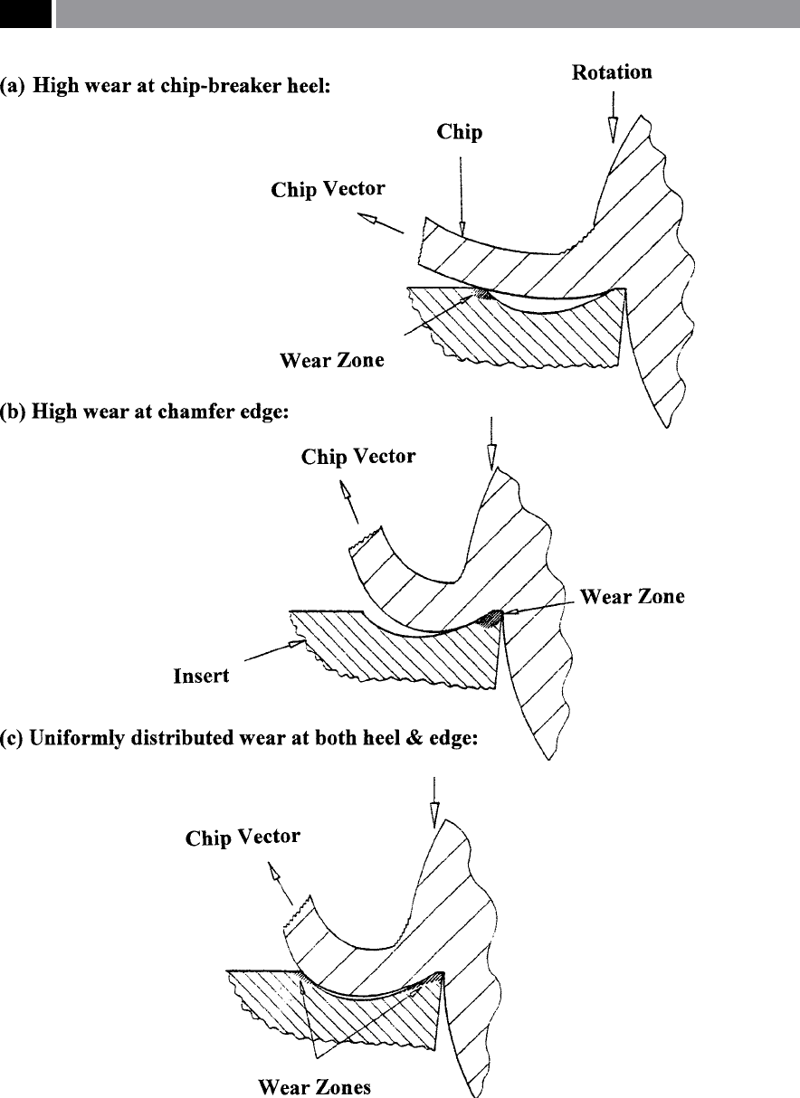
Figure 37. Schematic representations of diering chip-breaking insert tool wear mechanisms – due to altera-
tions in the cutting data. [Source: Jawahir et al., 1995]
.
80 Chapter 2