Smith G.T. Cutting Tool Technology: Industrial Handbook
Подождите немного. Документ загружается.


Figure 44. The twist drill geometry and associated chip shearing mechanism. [Source: C.J. Oxford Jr., 1955].
Drilling and Associated Technologies 91
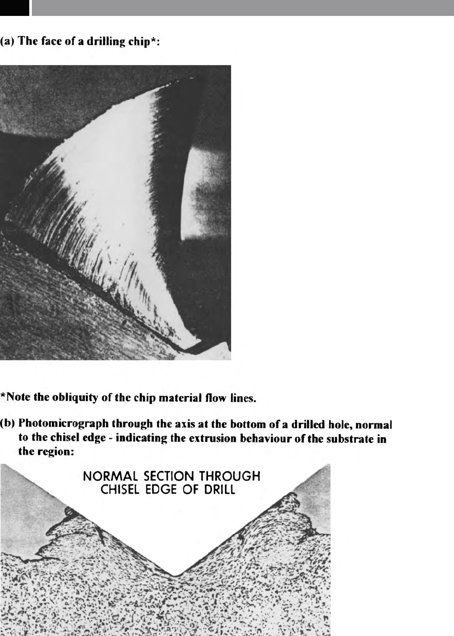
Figure 45. The twist drill shearing and extrusion mechanism at the bottom of a hole. [Source:
C.J. Oxford Jr., 1955]
.
92 Chapter 3
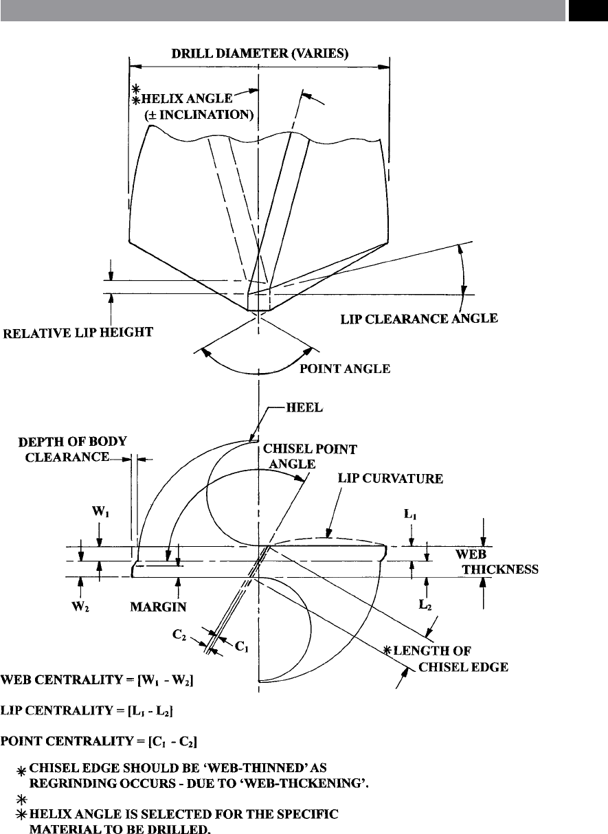
Figure 46. Twist drill geometry.
Drilling and Associated Technologies 93

mensional accuracy and roundness, with some ‘helical
wandering’
2
as the drill passes through the workpiece.
Hole accuracy and in particular the ‘bell-mouthing ef-
fe
ct’
3
, is minimised by previously centre-drilling prior
to drilling to ‘size’. e main cause of such this ‘bell-
mouthing’ is probably the inconsistency in the drill
geometry. Such eects are exacerbated using Jobber
drills
4
, or even worse, by utilising longer-series drills,
which tend to either slightly ‘unwind’ ,
or bend as a re-
sult of lessening rigidity promoting some drill bend-
ing/deection.
It is worth noting that the rigidity of a tool such
as a drill will decrease by the ‘square of the distance’
5
.
erefore it follows that the greater the drill penetra-
tion into the workpiece, the progressively larger the
deection and, the further from the ‘true axis of rota-
tion’ will be the subsequent drill’s path. is deected
drilled hole slope angle ‘ϕ’ , can be dened in the fol-
lowing manner:
Drilled hole slope angle
‘φ’ = 3
/2 l × R/T (1 – I/k × tan k l)
Where:
l = length of deected tool,
2 ‘Helical wandering’ is the result of the drill’s geometry be-
ing ‘unbalanced’ , resulting from of diering lip lengths, or an
oset chisel point, causing the drill to ‘spiral-down’ through
the workpiece, as it progresses through the part (see Fig. 70).
‘Bell-mouthing’ of the drilled hole is attributable to the chisel
point and is produced by the line-of-contact, as the drill point
initially touches the component’s surface, causing it to ‘walk’
until the feed/penetration stabilises itself at the outer corners
(i.e. margins) entering the workpiece, whereupon, these mar-
gins guide the drill into the part.
3 ‘Bell-mouthing eect’ is produced by the drill chisel point’s
eccentric behaviour as it attempts to centralise its rotational
motion as it enters, or exit’s the workpiece.
4 ‘Jobber drills’ are considered to be ‘standardised drills’ that
are normally utilised for most drilling general operations, un-
less otherwise specied.
5 ‘Rigidity rule’: a drill, reamer, tap, or a milling cutter held in
a spindle will have its rigidity decreased by the ‘square of the
distance’ ,
namely, if a drill is twice as long it is four times less
rigid.
NB A cantilevered tool such as a boring bar has its rigidity de-
creased by the ‘cube’ or the distance – meaning that too much
tool overhang, will seriously reduce tooling rigidity.
R = ratio of the transverse reaction at the drill point,
T =
thrust force,
I =
system’s ‘moment of inertia’ ,
k =
√T/E I.
As suggested above, this ‘axis slope error’ is initiated
when the chisel edge begins to penetrate the workpiece
and unless the feed is discontinued, or in some man-
ner the error is corrected, the magnitude of deection
will increase as drill penetration continues. e drill’s
m
agnitude of deection can reach up to 60 µm, under
exaggerated drilling conditions.
e geometry of the point has been the subject
of considerable research and development for many
years, with some unusual departures from the ‘stan-
dard’ 118° drill point included angle. Typical of these
e
xtreme approaches were the so-called ‘Volvo point’ ,
having a negative 185° included angle – primarily
utilised to avoid ‘
frittering’
6
of drilled holes, or the
highly positive geometries such as 80° included an-
gle used for drilling some plastics. Not only can the
point angle be modied, but the shape and prole of
the chisel point, or web
7
oers numerously-ground
opportunities for detailed geometric modications,
with only some of which being shown in Fig. 47. Four
of the most commonly-ground drill point geometries
being:
•
Conventional – the ‘original’ Morse geometry, hav-
ing a straight chisel edge, with poor self-centring
drilling action (Fig. 46a),
•
Split-point
8
– there are a range of point-splitting
techniques available to alter the point prole, which
has the eect of modifying the chisel point to allow
a reasonable self-centring action (Fig. 47b),
6 ‘Frittering’ refers to the break-out at the hole’s edge as the drill
exit’s the part, on some brittle materials, such as on several
Powder Metallurgy compacts.
7 ‘Web’ refers to the internal core of the drill – which imparts
mechanical strength to the drill. e web increases in thick-
ness the further one gets from the chisel edge (i.e. shown in
Fig. 47 – in lower diagrams and with cross-sections). Hence,
if the drill is reground many times, the chisel point width will
obviously increase, this necessitates that the chisel point must
b
e ‘thinned’ , otherwise too high a thrust force occurs and an
inecient drilling action will result.
8 ‘Split-point’ ground drills are sometimes referred to as ‘Multi-
facet drills’.
94 Chapter 3
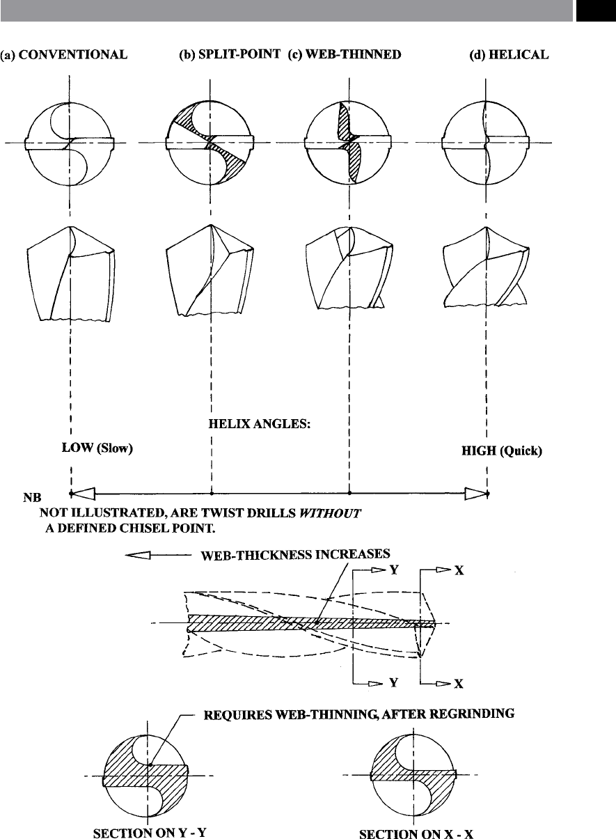
Figure 47. A range of typically ground twist drill points.
Drilling and Associated Technologies 95

•
Web-thinning – as its name implies, the chisel point
is web-thinned/notched, by regrinding to reduce
the width of the chisel point, while slightly modify-
ing the prole, giving a partial self-centring action
(Fig. 47c),
•
Helical – the chisel point is ground to an ‘S-shape’ ,
which modies both the chisel point and its pro-
led shape, improving the drilling performance
and self-centring action (Fig.47d).
NB On some drills a sophisticated grinding action
has imparted drills without a chisel point, which sig-
nicantly improves their drill penetration rates into
the workpiece, but requires a complex drill regrinding
operation to re-sharpen them when the edge becomes
‘dulled’.
Not only are drills supplied with appropriate point
geometries, but for twist drills the twin spiral utes
of the drill can also be specied – from the tooling
manufacturer, as this gives the drill its ‘equivalent of
the rake angle’ as found on a single-point turning tool.
On conventional jobber drills, the normal ute angle
is 29° – giving a relatively ‘slow’ helix (Fig. 47a) and in
the past, typically being utilised for drilling most plain
carbon steel grades. Conversely, a drill with a ‘quick’
helix angle (Fig. 47d), might be employed to drill so
materials such as certain plastics. Brittle materials on
the other hand, which might be utilised typically when
drilling Cartridge Brass (i.e. 70Cu 30Zn composition),
require a zero, or slightly negative helix.
NB It is possible to temporarily modify the drill’s he-
lix angle by re-grinding, termed ‘drill dubbing’ ,
which
refers to lightly ‘ash-grinding’ the utes at the lips to
decrease the eective ute helix angle.
e main strength of a drill is via its web, or its cross-
section which can be changed and as a result, will
modify the ute’s geometric prole (i.e. see Fig. 48).
In general, drill cross-section are classied in three
groups, namely:
•
Axe-shaped – having well-dened margins (Fig. 48
–top),
•
Rounded heel – with increased web, but small mar-
gins (Fig. 48 – middle),
•
Rhombic – incorporating a large web, with wide
margins (Fig. 48 – bottom).
NB Some twist drills feature oil/coolant holes to allow
cutting uid to reach right down toward the cutting
edges of the drill, increasing both tool life and improv-
ing the hole’s ‘
Surface Integrity’
9
.
3.1.3 The Dynamics
of Twist Drilling Holes
Introduction
e term ‘drilling’ refers to all production techniques
for the manufacture of cylindrical holes in workpieces
using chip-making cutting tools, for short-hole
10
and
deep-hole drilling operations. e expression ‘solid
drilling’ has been introduced in recent years – which is
hole-making generation undertaken in a single opera-
tion, to dierentiate it from that of the previous tech-
niques of either: centre-drilling or, pilot-hole drilling
(i.e, see Fig. 50b) prior to drilling to size. Drill technol-
ogy includes a range of specialised hole-making tool-
ing, including: twist drills, solid drills, counter-boring
and trepanning tools and deep-hole drills
11
. In the rst
instance, mention will be made of twist drilling opera-
tions, then a review of these other drilling production
methods will occur.
Twist Drills
Twist drilling operations have been carried out for
around 150 years, with a twist drill imparting ‘bal-
anced cutting conditions’ ,
assuming that the drill’s
geometry is symmetrical. It has been suggested that
the work of drilling may be considered as two single-
point lathe tools engaged in an internal straight turn-
ing operation. A twist drill produces both torque and
thrust as it rotates and is fed into the workpiece. e
main contribution to torque is through the lips, with a
small amount of torque being generated by the chisel
point as the drill rotates against the resistance of the
9 ‘Surface Integrity’ has been coined to describe the ‘altered ma-
terial zone’ (AMZ), for localised sub-surface layers that dier
from those of the bulk material – considerably more will be
said on this subject in Chapter 7.
10
‘Short-hole drilling’ operations cover depth-to-hole-diam-
e
ter-ratios of up to 6D (i.e. for diameters up to 30 mm), whilst
larger drilled holes are limited to depths of 2.5D.
Where: D = nominal drill diameter.
11 ‘Deep-hole drilling’ and ‘Gun-drilling’ operations are virtu-
ally the same, with the term Deep-hole drilling being the pre-
ferred term in this text.
96 Chapter 3
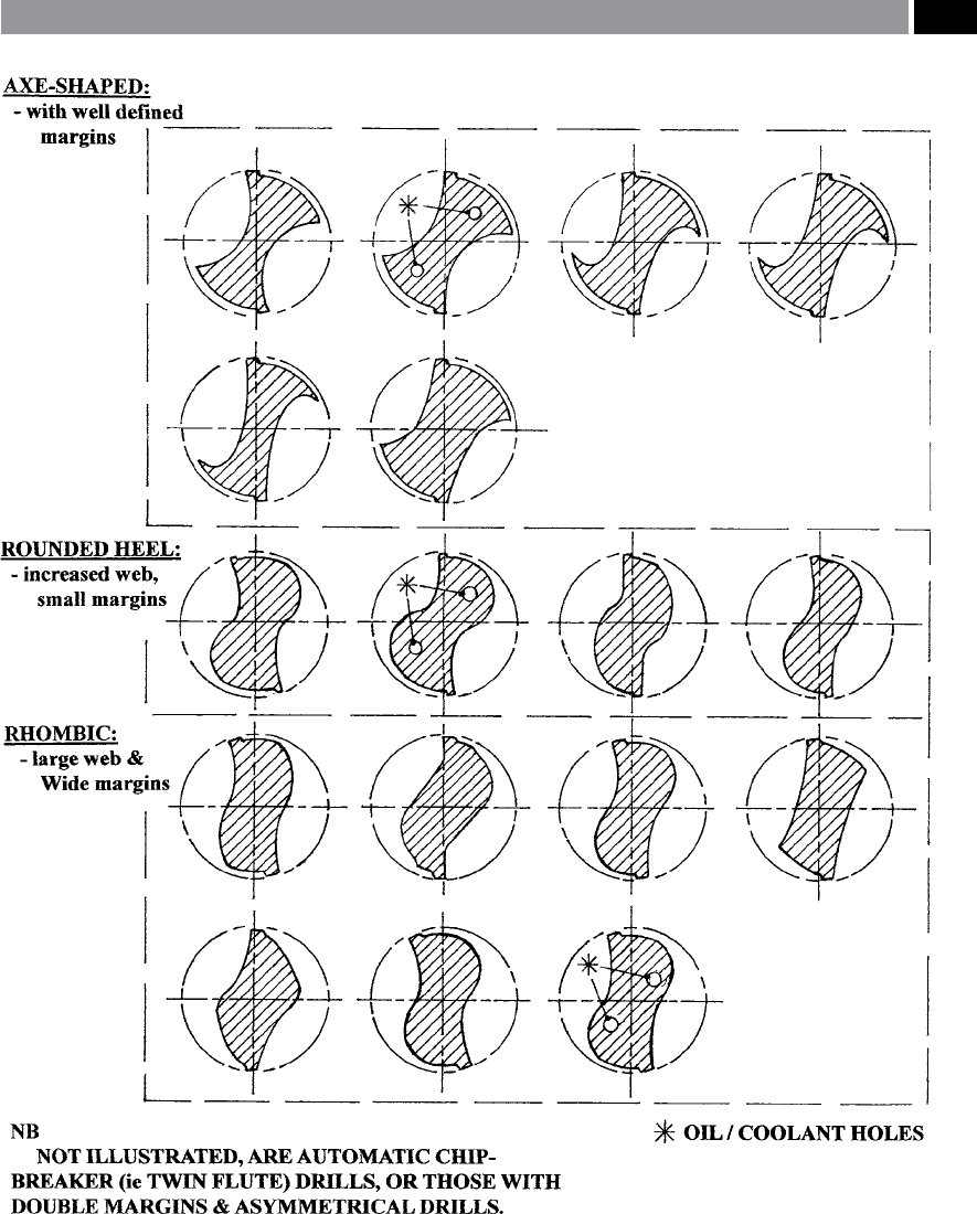
Figure 48. Symmetrical twist drill cross-sectional proles [After: Spur and Masuha, 1981].
Drilling and Associated Technologies 97

workpiece (see Fig. 49). e thrust force (Fig. 49) is
the result of the selected penetration rate (i.e. feed), in
combination with the bulk hardness of the workpiece
and its work-hardening ability and the eciency of the
coolant supply – if any – to the cutting edges (i.e lips).
e resolution of the cutting resistance into their vari-
ous components when twist drilling, is shown in Fig.
49 at a mid-point along the lips. e thrust force is just
one of the cutting resistances in a drilling operation,
contributions to drill resistance are from the:
•
Lips – equal lip lengths and angles are important
for a ‘balanced cutting action’ , this being consid-
ered an ecient cutting process,
•
Chisel edge – is highly negatively skewed and as it
acts like a ‘blunt wedge-shaped indentor’ , extrud-
ing the workpiece material from this vicinity,
Figure 49. The balanced cutting forces resulting from drilling holes utilising twist drill geometries. [After: Kaczmarek, 1976].
98 Chapter 3

•
Land, or margin – via a rubbing, or frictional ac-
tion.
NB e latter two are relatively inecient processes,
moreover, the resistance components of the lips and
chisel edge are the product of resistance of the unde-
formed chip to plastic strain, in combination with re-
sistance due to external friction. e land resistance
occurs from the friction (i.e. rubbing) against the side
of the drill’s hole.
When symmetrical twist drilling (illustrated in Fig.
50), the undeformed chip can be characterised by its:
•
Cutting depth (a) – where ‘a’ = d/2, with ‘d’ being
the drill’s diameter (mm),
•
Feedrate (s) – this being the distance the cutting
edge moves in the drilling axis direction during
one revolution. Normally two rigidly joined cut-
ting edges are cutting at any instant, each one in its
travel corresponds to feed ‘s
z
’ , which removes an
undeformed chip whose size – in the direction of
the drilling axis is: ‘s
1
’ and ‘s
2
’ respectively (i.e see
Fig. 50a) and, as most drills are symmetrical in de-
sign, then:
s = s
1 = s2 = s/2 (mm),
•
Undeformed chip thickness (h
z
) – to be removed by
each of the drill’s cutting lips, which can be deter-
mined from the following relationship:
h
z
= s
z
sinθ (mm).
NB W
ith a symmetrical drill, then: H
z
= h
1
= h
2
.
•
Undeformed chip thickness (b) – can be found from
the following relationship:
b = a 1/sinθ = d/2sinθ (
mm).
∴ It follows from these expressions, that the trans-
verse cross-sectional area of the undeformed chip at
each of the twist drill’s cutting lips, can be shown by
the following relationship:
A
z
= s
z
d/2 = sd/4 = h
z
b (mm
2
).
Hence, the total transverse cross-sectional area when
drilling of the undeformed chip will be:
A = 2
A
z
= s
z
d = sd/2 = 2h
z
b (mm
2
).
Conversely, in the case of ‘Pilot’ hole drilling (Fig.
50b), the undeformed chip elements are identical to
‘Solid’ drilling, but for the exception of the D
OC
, which
can be expressed in the following manner:
a = d-d
o
/2 (mm).
Where:
d = d
iameter of nal hole (mm),
d
o
= diameter of primary hole (mm).
us, for example in the case of ‘Pilot’ hole drilling,
the total cross-sectional area of the undeformed chip,
will be:
A = 2A
z
= s
z
(d – d
o
) = s(d – d
o
)/2 = 2h
z
b (mm
2
).
e calculation of cutting forces in ‘Solid’ hole drilling
(Fig. 50a), can be found from the general formulae for
axial force (F) and torque (M), in the following man-
ner, respectively:
F = C
F
d
bF
s
uF
K
H
(kg)
M = C
M
d
bM
s
uM
K
H
(kg mm)
Where:
C
F
12
and C
M
13
= constants (i.e. derived from Kacz-
marek‘s ndings),
d =
nominal drill diameter (mm),
bF and bM =
exponents characterising the inu-
ence of the drill diameter,
s =
feed rate (mm rev
–1
),
uF and uM =
exponents characterising inuence of
feedrate,
K
H
= workpiece material’s correction co-
ecient (i.e. concerning mechanical
properties).
12 C
F
is derived from experimental data, typically: Carbon steel
(construction) 84.7, Grey CI 60.5, Malleable CI 52.5, Bronze
(medium hardness) 31.5 – with HSS drills, ranging from φ10
to 60 mm.
13 C
M
is derived from experimental data, typically: Carbon steel
(construction) 33.8, Grey CI 23.3, Malleable CI 20.3, Bronze
(medium hardness) 12.2 – with HSS drills, ranging from φ10
to 60 mm.
Drilling and Associated Technologies 99

Figure 50. Drilling a hole with/without a ‘pilot’ hole and the cutting, rubbing and extrusion mechanism. [After: Kaczmarek,
1976]
.
100 Chapter 3