Smith G.T. Cutting Tool Technology: Industrial Handbook
Подождите немного. Документ загружается.

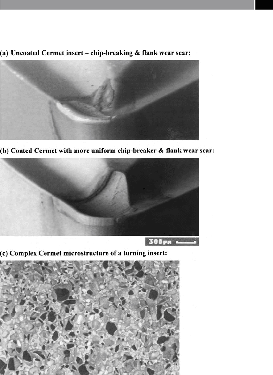
Figure 38. Improved wear resistance obtained with an uncoated and coated cermet, when turning
ovako 825B steel, having the following cutting data: Cutting speed 250 m min
–1
, feed 0.2 mm rev
–1
,
D
oC
1.0 mm and cut dry. [Courtesy of Sandvik Coromant]
.
Turning and Chip-breaking Technology 81

grooving, enabling the non-productive elements
42
in
the machining cycle to be minimised. In the original
multi-directional tooling concept, the top rake geom-
etry might include a three-dimensional chip-former,
comprising of an elevated central rib, with negative K-
lands on the edges. Such a top rake prole geometry
could be utilised for ecient chip-forming/-breaking
of the resultant chips. is tooling when utilised for
say, grooving operations, employed a chip-forming
geometry – this being extended to the cutting edge,
which both narrowed and curled the emerging chip
to the desired shape, thereby facilitating easy swarf
evacuation. A feature of this cutting insert concept,
was a form of eective chip management, extending
the insert’s life signicantly, thus equally ensuring that
adequate chip-ow and rapid swarf evacuation would
have taken place. When one of these multi-directional
tools was required to commence a side-turning opera-
tion, the axial force component
43
acting on the insert
caused it to elastically deect at the front region of the
toolholder. is tool deection enabled an ecient
feed motion along the workpiece to take place, be-
cause of the elastic behaviour of the toolholder created
a positive plan approach angle in combination with a
front clearance angle – see Fig. 39a and b (i.e. illus-
trating in this one of the latest ‘twisted geometry’ insert
multi-functional tooling geometries).
Any of today’s multi-functional tooling designs
(Figs. 39 and 40), allow a ‘some degree’ of elastic be-
haviour in the toolholder, enabling satisfactory tool
vectoring to occur, either to the right-, or le-hand
of the part feature being machined. ese multi-func-
42 Non-productive elements are any activity in the machining
cycle that is not ‘adding value’ to the operation, such as: tool-
changing either by the tool turret’s rotation, or by manually
changing tools, adjusting tool-osets (i.e. for either: tool wear
compensation, or for inputting new tool osets – into the ma-
chine tool’s CNC controller), for component loading/unload-
ing operations, measuring critical dimensional features – by
either touch-trigger probes, non-contact measurement, or
manual inspection with metrology equipment (i.e. microme-
ters, vernier calipers, etc.), plus any other additional ‘idle-time’
activities.
43 A
n Axial force component is the result of engaging the desired
feedrate, to produce features, such as: a diameter, taper, pro-
le, wide groove, chamfer, undercut, etc. – either positioned
externally/internally for the necessary production of the ma-
chined part.
tional tools are critically-designed so that for a specic
feedrate, the rate of elastic deection is both known
and is relatively small, being directly related to the ap-
plied axial force, in association with the selected D
OC
’s.
At the tool-setting stage of the overall machining cycle,
compensation(s) are undertaken to allow for minute
changes in the machined diameter, due to the dynamic
elastic behaviour of one of these tools in-cut. For a
specic multi-functional tool supplied by the tooling
manufacturer, its actual tool compensation factor(s)
will be available from the manufacturer’s user-manual
for the product.
In-action these multi-functional tools (Fig. 39b),
can signicantly reduce the normal tooling inventory,
for example, on average such tools can replace three
conventional ones, with the twin benet of a major
cycle-time reduction (i.e. for the reasons previously
mentioned) of between 30 to 60% – depending upon
the complexity of features on the component being
machined. Some other important benets of using a
multi-functional tooling strategy are:
•
Surface quality and accuracy improvements – due
to the prole of the insert’s geometry, any ‘machined
c
usps’
44
, or feedmarks are reduced, providing excel-
lent machined surface texture and predictable di-
mensional control,
•
Turret utilisation improved – because fewer tools
are need in the turret pockets, hence ‘sister tooling’
can be adopted, thereby further improving any un-
tended operational performance,
•
Superior chip control – breaks the chips into man-
ageable swarf, thus minimising ‘
birds nests’
45
and
entanglements around components and lessens au-
tomatic part loading problems,
•
Improved insert strength – allows machining at sig-
nicantly greater D
OC
’s to that of conventional in-
44 ‘Machined cusps’ the consequence of the insert’s nose geom-
etry coupled to the feedrate, these being superimposed onto
the machined surface, once the tool has passed over this sur-
face.
45 ‘Birds nests’ are the rotational entanglement and pile-up
of continuous chips at the bottom of both trough and blind
holes, this work-hardened swarf can cause avoidable damage
in the machined hole, furthermore, it can present problems in
coolant delivery for additional machining operations that may
be required.
82 Chapter 2
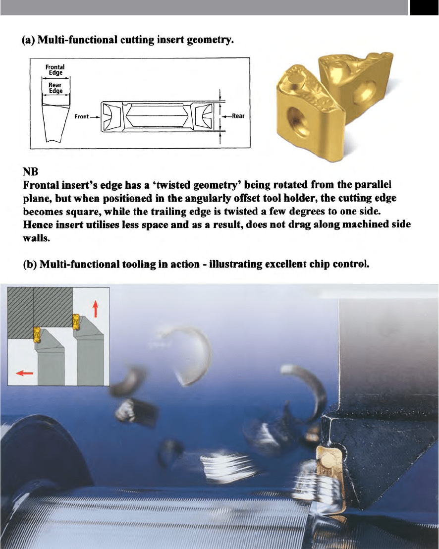
Figure 39. Multi-functional cutting insert geometry for ecient stock removal and increased part productivity. [Courtesy of Iscar
Tools]
.
Turning and Chip-breaking Technology 83
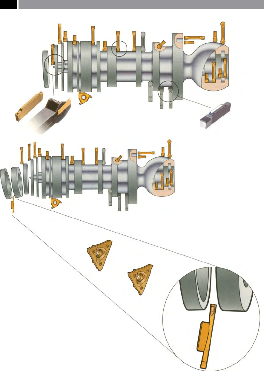
Figure 40. Multi-functional tooling for the machining of rotational features such as: turning, grooving and proling operations –
having excellent chip control. [Courtesy of Sandvik Coromant]
.
84 Chapter 2
serts, with improved insert security its toolholder
location,
•
CNC programming simplied – many tooling man-
ufacturer’s have specially-prepared soware to sig-
nicantly reduce CNC programming input times.
NB
is latter point utilises CNC ‘canned cycles’ to
reduce program lengths.
In Appendix 3, a guide for ‘Trouble-shooting for turn-
ing operations’ are listed, with possible causes and rem-
edies to potential production problems.
In the following chapters, many other important
chip-forming production processes will be discussed,
with hole-making techniques such as drilling being
around 25% of all manufacturing techniques under-
taken by machining-related companies – these and
associated hole-production methods will be reviewed
next.
References
Journal and Conference Papers
Boston, O.W. A Research into the Elements of Metal Cutting
Trans ASME 48, 749–848, 1926.
Cocquilhat, M. Experiences sur la Résistance utile Produ-
ite dans le Forage Ann. Trav. Publ.en Belgique 10, 199,
1851.
Doi, S. and Kato, S. Chatter Vibration of Lathe Tools, Trans.
of ASME, Vol. 78 (5), 1127–1134, 1956.
Fabry, D. e Tool Channel. Cutting Tool Eng’g, 58–64,
Sept. 2003.
Gadzinski, M. Parting Know-how. Cutting Tool Eng’g,
52–57, March 2001.
Galloway, D.F. Some Experiemnts on the Inuence of Vari-
ous Factors on Drill Performance. Trans. of ASME,
191–231, Feb., 1957.
Humphries, J.R. Energing Technologies and Recent Ad-
vances in Multi-functional Groove/Turn Systems. Int.
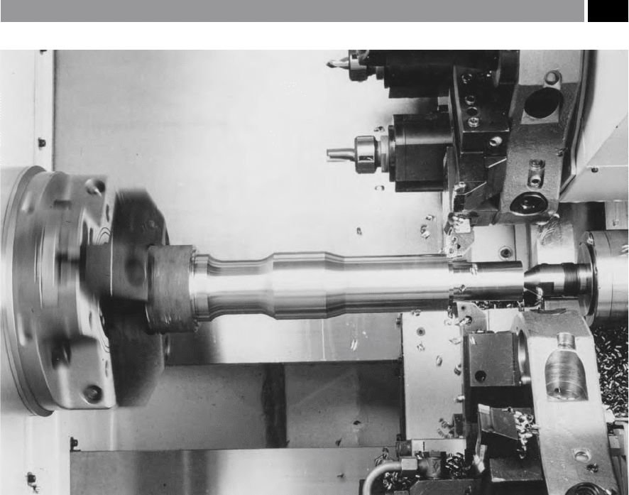
Figure 41. By employing twin turrets on a mill/turn centre, ‘balanced turning’ of the component can remove large volumes of
stock at one pass. [Courtesy of DMG (UK) Ltd.]
.
Turning and Chip-breaking Technology 85

Conf. on Industrial Tooling, Shirley Press Ltd, 65–85,
Sept. 1979.
Isakov, E. e Mathematics of Machining. American Ma-
chinist, 37–39, Aug. 1996.
Isakov, E. Reassessing Power Factors. American Machinist,
43–45, Dec. 1996.
Jawahir, I.S. e Tool Restricted Contact Eect as a Major
Inuencing Factor in Chip-breaking: An Experimen-
tal Analysis. Annals of the CIRP, Vol. 31 (1), 121–126,
1988.
Jawahir, I.S., Ghosh, R., Fang, X.D. and Li, P.X. An Inves-
tigation of the Eects of Chip-ow on Tool Wear in Ma-
chining with Complex Grooved Tools. WEAR, Vol.184
(2), 145–154, 1995.
Kasahara, N., Sato, H. and Tani, Y. Phase Characteristics of
Self-excited Chatter in Cutting. J. of Engg for Ind., ASME
Pub, Vol. 114, 393–399, Nov. 1992.
Kennedy, B. Facing Facts. Cutting Tool Eng’g, 29–37, Feb.
2002.
Kennedy, B. Take a Bigger Bite. Cutting Tool Eng’g, 25–29,
Aug. 2003.
King, K. Added Functionality. Cutting Tool Eng’g, 52–55,
Feb. 2005.
Kondo, Y., Kawano, O. and Sato, H. Behaviour of Self-excited
Chatter due to Multiple Regenerative Eect. J. of Engg.
For Ind., ASME Pub., Vol. 103 (3), 324–329, 1981.
Lewis, B. Turn your Wipers on. Cutting Tool Eng’g, 47–51,
Jan. 2003.
Mallock, A. e Action of Cutting Tools. Proc. of Royal Soc.
Lond. 33, 127–139, 1881–882.
Paterson, H. Strictly Boring. Cutting Tool Engg., 22–30,
Oct. 1995.
Pekelharing, A.J. Built-up Edge (BUE): is the Mechanism
Understood? Annals of the CIRP, Vol. 23 (3) 207–211,
1974.
Piispanen, V. Eripanines Teknilliseslä Aikakauslehdeslä 27,
315, 1937.
Reuleaux, F. Uber den Taylor Whiteschen Werkzengstahl in
Verein zur Beförderung des Gewerbeeisses in Preus-
sen. Sitzzungsberichte, 79, 179, 1900.
Smith, G.T. Fundamentals of Chip-breaking for Continuous
Cutting Operations. Int. Conf. on Industrial Tooling,
Molyneux Press Ltd, 72–82, Sept. 1999.
Teets, B. Facing up to Grooving Problems. Machinery and
Prod. Eng’g., 51–52, Oct. 1988.
Time, I. Soprotivlenie Metallov I Dereva Rezaniju St. Peters-
burg, 1870.
Tipnis, V.A. and Joseph, R.A. Testing for Machinability, in:
Inuence of Metallurgy on Machinability, ASM Pub.
11–30, 1975.
Tresca, H. Mémoire sur le Rabotage des Métaux
Bull. Soc. d’Encourgement pour I’Industrie
Nationale 585–685, 1873.
Venkatesh, V.C. and Satchidanandam, M. A Discussion on
Tool Life Criteria and Total Failure Causes. Annals of the
CIRP, Vol. 29 (1), 19–22, 1980.
Watson, D.W. and Murphy, D.C. e Eect of Machining
on Surface Integrity. Metallurgist and Matls, 199–204,
April 1979.
Webzell, S. Wiping away Cycle Times. Metalworking Prod.,
Oct. 2003.
Books, booklets and guides
Armarego, E.J.A. and Brown, R.H. e Machining of Met-
als. Prentice-Hall Pub., 1969.
Boothroyd, G. and Knight, W.A. Fundamentals of Metal
Machining and Machine Tools. Marcel Dekker (NY),
1989.
Finish Turning – Application Guide. AB Sandvik Coromant
Pub., 1995.
Hartig, E. Versuche über Leistung und Arbeitsverbrauch der
Werkzengmaschine. 1873.
Kaczmarek, J. Principles of Machining by Cutting Abrasion
and Erosion. Peter Pregrinus Pub. (Warsaw), 1976.
Modern Metal Cutting – A Practical Handbook. AB Sandvik
Coromant Pub., 1994.
Shaw, M.C. Metal Cutting Principles. Clarendon Press, Ox-
ford, 1984.
Smith, G.T. Advanced Machining – e Handbook of Cut-
ting Technology. IFS/Springer Verlag, 1989.
Smith G.T. CNC Machining Technology. Springer Verlag,
1993.
Smith, G.T. Industrial Metrology – Surfaces and Roundness.
Springer Verlag, 2002.
Stainless Steel Turning, AB Sandvik Coromant Pub., 1996.
Tlusty, G. Manufacturing Processes and Equipment. Pren-
tice Hall, 2000.
Trent, E.M. Metal Cutting. Oxford: Butterworth Heine-
mann (3
rd
Ed.), 1991.
86 Chapter 2

3
Drilling and Associated
Technologies
‘In all things, success depends upon previous preparation
and without such preparation……there is sure to be failure.’
CONFUCIUS
(c550–c487BC)
[Analects]

3.1 Drilling Technology
3.1.1 Introduction to the Twist
Drill’s Development
Drilling operations are perhaps the most popular ma-
chining process being undertaken today, with their
origins being traced back to cutting tool develop-
ments in North America in the 19
th
century. In 1864
toward the latter part of the American Civil War, Ste-
ven Morse (i.e. later to design the signicant ‘Morse
taper’ – for accurate location of the ‘sleeved drills’
into their mating machine tool spindles) founded
the Morse Twist Drill and Machine Company in the
‘North’. Morse then proceeded to develop probably the
most important cutting tool advance to date, namely,
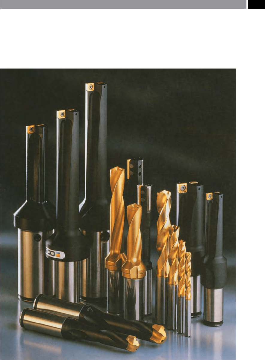
the ubiquitous twist drill. In Fig. 42, several of today’s
twist drills are illustrated along with just a small range
of ‘solid’ contemporary designs. Morse’s originally-de-
signed twist drill has changed very little over the last
150 years – since its conception. In comparison to the
somewhat cruder-designed contemporary drills of that
time, Morse stated: ‘e common drill scrapes metal to
be drilled, while mine cuts the metal and discharges the
chips and borings without clogging’. Morse’s statement
was at best, to some extent optimistic, whereas the
‘cold reality’ tells a dierent story, as a drill’s perfor-
mance is inuenced by a considerable number of fac-
tors, most of which are listed in Fig. 43.
3.1.2 Twist Drill Fundamentals
e basic construction of a conventional twist drill is
depicted in Fig. 44a. From this illustration two dis-
tinct cutting regions can be established: rstly, the
main cutting edge, or lips; secondly at the intersection
of the clearance and main cutting edge – termed the
chisel edge. In fact for a twist drill, the cutting process
can be equated to that of a le-hand oblique turning
tool, where the rake and clearance face geometries are
identical and the correlation between these two ma-
chining processes have been validated in the experi-
mental work by Witte in 1982. Both of these regions
remove material, with the cutting lips producing ef-
cient material removal, while the chisel edge’s con-
tribution is both inecient and is mainly responsible
for geometric errors in drilling, coupled to high thrust
loads.
e main cutting edges are accountable for a rela-
tively conventional chip formation, as shown in the
‘quick-stop’ photomicrograph in Fig. 44b. An oblique
cutting action occurs to the direction of motion, being
the result of an oset of the lips that are parallel to a
radial line – ahead of centre – which is approximately
equal to half the drill point’s web thickness and in-
creases toward the centre of the drill. is obliquity is
responsible for inducing chip ow in a direction nor-
mal to the lips in accordance with Stabler’s Law
1
. e
increasing chip ow obliquity can be seen in Fig. 45a,
by observing the ow lines emanating from the chip’s
interface along the lips and up the ute face. Such
an oblique cutting action serves to increase the twist
drill’s eective rake angle geometry. With the advent
of ‘Spherical trigonometric computer soware’ for ob-
taining direct three-dimensional calculations – previ-
ously described by Witte (1982) in two-dimensional
formulae for cutting edge performance – these calcu-
lations have been enhanced.
Under the chisel point, or web, the material re-
moval mechanism is quite complex. Near the bottom
of the utes where the radii intersect with the chisel
edge, the drill’s clearance surfaces form a cutting rake
surface that is highly negative in nature. As the centre
of the drill is approached, the drill’s action resembles
t
hat of a ‘blunt wedge-shaped indentor’ , as illustrated
in Fig. 45b. An indication of the inecient material
removal process is evident by the severe workpiece
deformation occurring under the chisel point, where
such deformed products must be ejected by the drill to
produce the hole. ese ‘products’ are extruded, then
wiped into the drill ute whereupon they intermingle
with the main cutting edge chips. is fact has been
substantiated by force and energy analysis, based on a
combination of cutting and extruding behaviour under
the chisel point, where agreement has been conrmed
with experimental torque and thrust measurements.
e chisel edge in a conventionally ground twist drill
has no ‘true’ point, which is one of the major sources
for a drilled hole’s dimensional inaccuracy.
1 Stabler’s Law – for oblique cutting, can be formulated, as be-
low:
Chip ow (cos η) = cos I (b
c
/b)
Where: I = inclination of cutting edge, b
c
= chip ow vector,
b = direction of cutting vector.
88 Chapter 3
e conventional twist drill chisel point geometry
can be seen in Fig. 46, together with associated no-
menclature for critical features and tolerance bound-
aries. From the relatively complex geometry and
dimensional characteristics shown in Fig. 46, the ob-
tainable accuracy of holes generated whilst drilling is
dependent upon grinding the drill to certain limits.
Any variations in geometry and dimensions, such as:
dissimilar lips and angles, chisel point not centralised,
and so on, have a profound eect on both the hole di-
Figure 42. A selection of just some of the many ‘solid’ and ‘through-spindle’ drilling varieties and ‘inserted-edge’
insert geometries currently available. [Courtesy of Seco Tools]
.
Drilling and Associated Technologies 89
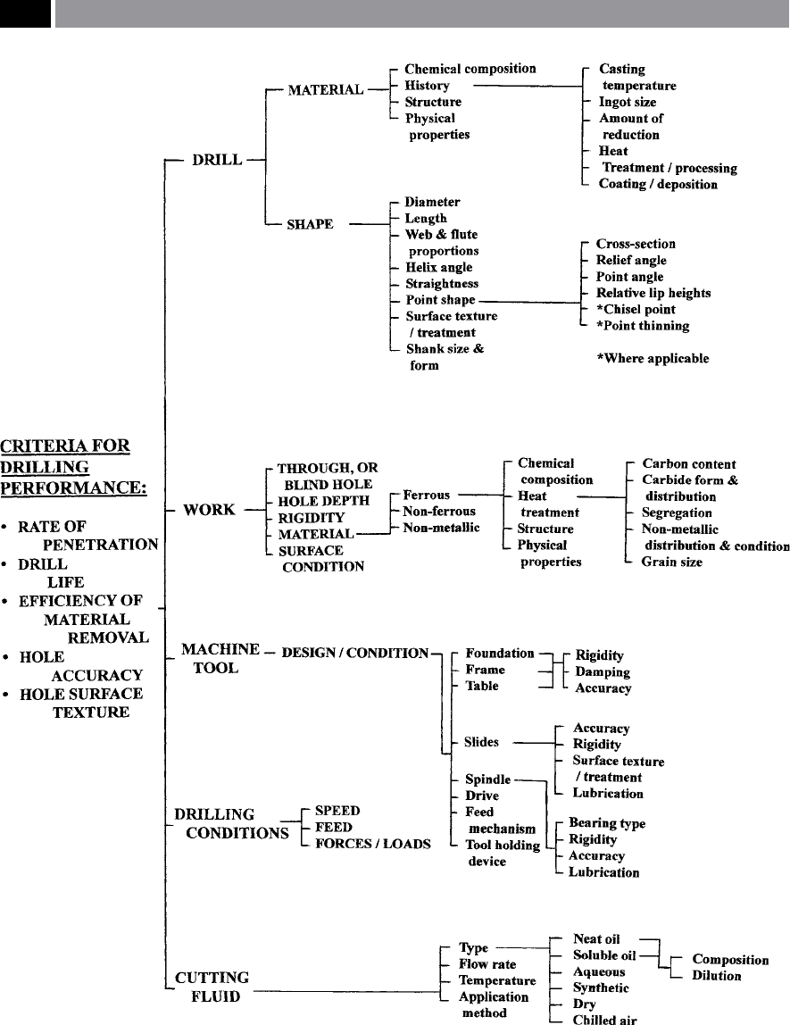
Figure 43. The principal technical drill performance criteria and factors associated with drilling operations in this case for ex-
ample, on castings
.
90 Chapter 3